TRAXX DBM200-3 Operating Manual Download Page 8

8

To connect the water supply. Attach the quick-release water coupling to a water hose.   

WARNING: Never allow water to enter the motor. It could lead to an electric shock. 

WARNING: Check all connections of the water feed system to ensure there 
are no leaks. Inspect hoses and other critical parts which could deteriorate.

WARNING: The maximum water pressure should not exceed 70 psi (4 bar).

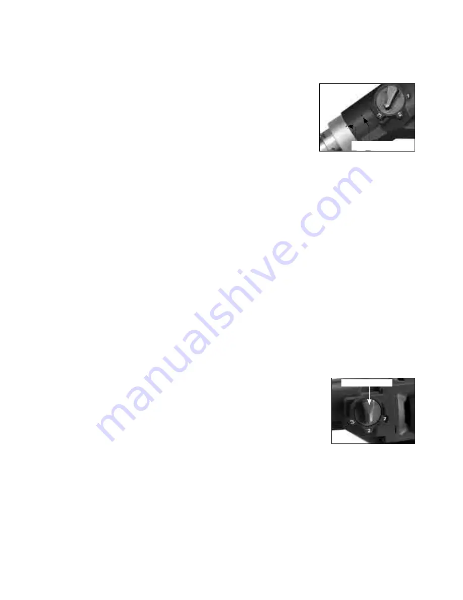
CAUTION: There are two small holes on the top of the gearcase. If either 
of these holes leaks water, it indicates that the water seals are worn out. 
Replace them immediately.  

CAUTION: Never use a wet-only  machine without water feed. Running dry will overheat and destroy its 
water seals. Only convertible models may be used dry.

  
Use a water collector with a wet vacuum to collect cooling water if nearby objects could be damaged by water.

WARNING: Never allow water to enter the motor. A perfectly functioning water collector set up must be 
used for any drilling performed at an upward angle.


Instructions for Inserting Adaptors for Convertible models:

To attach either the water feed adaptor head or the vacuum adaptor, the universal port on the machine's 
gearbox is a bayonet connection. Align the slots on the adaptor with the tangs on the port. Insert fully and 
then twist clockwise to tighten.

3) SELECTING SPEEDS

There are 3 speed ranges to suit the bit size  and work piece hardness.  Choose the  
slowest speed  for  large  diameter  bits  and  hard materials. If when cutting the bit 
stalls repeatedly, then you must change to a lower gear. If you are already in the 
lowest gear and the bit stalls repeatedly, then you are using the machine over its 
maximum capacity. 

CAUTION:  Never  attempt  to  change  gears  on  a  running  machine!  Only  adjust  when  the machine is 
at rest.

Select the desired gear range by turning the gear selector either clockwise or counterclockwise into the desired 
gear. It will usually be necessary to turn the spindle by hand a little to get it to shift all the way.

 Gear Selector

 Indicator Holes

Summary of Contents for DBM200-3

Page 1: ...DBM200 3 DIAMOND CORE DRILLING MACHINES OPERATING MANUAL CAUTION Machine equipped with overheat thermal protection When the thermal protection kicks in always remove from the work piece and run at no load for at least 3 minutes to allow motor to cool before returning to operation ...

Page 2: ...ead 1 1 4 UNC 1 2 BSP Neck Diameter 60mm Dimensions 528mm X 106mm X 145mm 437mm X 115mm X 289mm Net Weight 6 4kg 14 Lbs Indicator Light Bull s Eye Level Port Water FeedValve Coupling Water Feed Adaptor Head Vacuum Adaptor Head Convertible Models Water Feed Valve Quick Release Water Coupling D Handle Model Spindle 1 1 4 UNC 1 2 BSP Side Handle Assy Indicator Light Bull s Eye Level Trigger Switch Tu...

Page 3: ...moving parts Damaged or entangled cords increase the risk of electric shock e When operating a power tool outdoors use an extension cord suitable for outdoor use Use of a cord suitable for outdoor use reduces the risk of electric shock f If operating a power tool in a damp location is unavoidable use a residual current device RCD protected supply Use of an RCD reduces the risk of electric shock 3 ...

Page 4: ...d users e Maintain power tools Check for misalignment or binding of moving parts breakage of parts and any other condition that may affect the power tool s operation If damaged have the power tool repaired before use Many accidents are caused by poorly maintained power tools f Keep cutting tools sharp and clean Properly maintained cutting tools with sharp cutting edges are less likely to bind and ...

Page 5: ... the event of a drilling core dropping out no personal injury or material damage will result When drilling hollow components check the flow route of the cooling water in order to prevent damage Always hold the machine tightly Diamond core drilling bits can become stuck at any time during core drilling there is a danger of the machine jumping out of control WARNING Pull the plug out of the socket b...

Page 6: ... use Press the Test button to test Press the Reset button to energize the circuit to the machine WARNING 110V UK machines are not equipped with a PRCD portable residual current device or GFCI ground fault circuit interrupter The machine must always be used with an isolating transformer for protection in case an electrical fault should occur Use an RCD in a separate control box with one or more soc...

Page 7: ...ered bits and cannot be dressed resharpened Once they become dull they must be replaced They tend to work well with softer abrasive materials like brick Sintered bits also known as wet type are much longer lasting but require operator knowledge for best results Water is absolutely always required with sintered bits The bit is impregnated with many layers of diamond in its metal matrix As the matri...

Page 8: ...r collector set up must be used for any drilling performed at an upward angle Instructions for Inserting Adaptors for Convertible models To attach either the water feed adaptor head or the vacuum adaptor the universal port on the machine s gearbox is a bayonet connection Align the slots on the adaptor with the tangs on the port Insert fully and then twist clockwise to tighten 3 SELECTING SPEEDS Th...

Page 9: ...no load for a few minutes to cool it before continuing Overheat Thermal Protection If the temperature of the motor gets too high the thermal protection will shut the motor down and the LED indicator light will glow solid red The switch must be first shut off and then restarted When this happens do not immediately start drilling after restarting the motor Always run the machine at no load for a few...

Page 10: ... may reduce the water flow If the exiting water is thick and muddy then increase the water It s very important that the water has enough pressure to flush cutting debris out of the cut 4 Once in the cut use steady feed pressure for about 30 seconds then back off feed pressure for a few seconds to allow cutting debris to escape the kerf cutting area and for the cutting surface of the bit to cool Th...

Page 11: ...work it loose If embedded steel such as rebar is encountered take special care When the steel is encountered the water will generally go clear and vibration will begin Change to a lower gear if available Reduce the feed pressure by about 1 3 and let the bit go at its own pace if there is too much vibration the bit will be destroyed Once the steel is passed continue normally A properly sharp bit wi...

Page 12: ...es while using compressed air CAUTION When drilling in a position with the motor near to the floor take measures to prevent dust debris and slurry from being sucked into the motor s cooling slots MAINTENANCE Every 50 hours of operation blow compressed air through the motor while running at no load to clean out accumulated dust If operating in especially dusty conditions perform this operation more...

Page 13: ...re not to strain the wiring 2 Using pliers rotate the brush spring out of the way and slide the old carbon brush out of the brush holder 3 Unscrew the screw to remove the brush lead The old carbon brush may now be lifted away 4 Install a new brush Installation is the reverse of removal 5 Replace the motor tail cover For D handle models replacement of the D handle is the reverse of removal Take car...

Page 14: ...15 WIRING LED 1 2 1 2 AC BRUSH BRUSH STATOR BLACK BLACK BLACK BLACK BLACK TEMP SENSOR ELECTRONICS UNIT SWITCH WHITE WHITE ...

Page 15: ... 67 66 68 71 54 53 52 51 50 49 48 30 31 32 33 34 35 36 25 91 29 28 55 65 38 37 39 40 42 44 45 46 97 14 14 07 13 09 15 15 12 11 74 NO 01 99 V1 9 64 63 85 17 18 19 22 21 26 99 56 60 59 81 84A 86 89 94 39 27 08 93 90 83 82 95 96 84B OPTIONAL 98 04 05 06 03 01 02 ...

Page 16: ...INPUT SHAFT M1 25 x 24T x 12T x 8T 1 47 N A 48 NEEDLE BEARING HK1010 1 49 RETAINING RING ISTW 14 1 50 OUTPUT GEAR M1 25 x 29T 1 NO Parts Name Q TY 51 SLIDING GEAR M1 25 x 42T 1 52 RETAINING RING ISTW 18 1 53 OUTPUT GEAR M1 25 x 46T 1 54 OIL SEAL Ø22 x Ø32 x 7 1 55 GEAR CASE 1 56 SOCKET CAP SCREW M5 x 12 1 57 N A 58 N A 59 O RING Ø3 x Ø20 x Ø26 1 60 GEAR SELECTOR 1 61 62 N A 63 WATER FEED CONNECTOR...

Page 17: ...1 7 14 06 16 80 79 78 77 77 75 71 54 53 52 51 50 49 48 27 30 31 32 33 34 35 36 25 29 28 55 65 38 37 39 40 42 44 45 46 98 74 64 63 85 18 19 22 21 26 100 56 60 59 86 70 69 67 66 68 17 89 90 95 39 76 92 93 94 91 81 83 82 96 97 84A 84B OPTIONAL 99 05 04 09 01 03 02 07 ...

Page 18: ...x 24T x 12T x 8T 1 47 N A 48 NEEDLE BEARING HK1010 1 49 RETAINING RING ISTW 14 1 50 OUTPUT GEAR M1 25 x 29T 1 NO Parts Name Q TY 51 SLIDING GEAR M1 25 x 42T 1 52 RETAINING RING ISTW 18 1 53 OUTPUT GEAR M1 25 x 46T 1 54 OIL SEAL Ø22 xØ32 x 7 1 55 GEAR CASE 1 56 SOCKET CAP SCREW M5 x 12 1 57 N A 58 N A 59 O RING Ø3 x Ø20 x Ø26 1 60 GEAR SELECTOR 1 61 62 N A 63 WATER FEED CONNECTOR KIT 1 64 WATER COU...

Page 19: ... 30 31 32 33 34 35 36 25 92 29 28 55A 65 38 37 39 40 42 44 45 46 14 14 07 13 09 15 15 12 11 74 NO 01 111 Version 2 0 85 17 18 19 22 21 26 104 56 60 59 81 86 89 94 39 27 08 93 90 83 82 100 101 84B OPTIONAL 102 103 04 05 06 03 01 02 111 110 108 109 108 108 107 106 105 98 99 97 96 95 FOR NO 55A FOR NO 55B 55B 84A ...

Page 20: ...1 51 SLIDING GEAR M1 25 x 42T 1 52 RETAINING RING ISTW 18 1 53 OUTPUT GEAR M1 25 x 46T 1 54 OIL SEAL Ø22 x Ø32 x 7 1 55A B GEAR HOUSING 1 NO Parts Name Q TY 56 SOCKET CAP SCREW M5 x 12 1 57 N A 58 N A 59 O RING Ø3 x Ø20 x Ø26 1 60 GEAR SELECTOR 1 61 64 N A 65 SOCKET CAP SCREW M5 x 50 4 66 WATER SEAL Ø25 x Ø45 x 7 1 67 WATER SEAL Ø25 x Ø47 x 7 1 68 INTERNAL CIRCLIP R 47 1 69 EXTERNAL CIRCLIP S 25 1...

Page 21: ...77 75 71 54 53 52 51 50 49 48 27 30 31 32 33 34 35 36 25 29 28 65 38 37 39 40 42 44 45 46 74 18 19 22 21 26 104 56 60 59 86 70 69 67 66 68 17 89 90 94 39 76 92 08 93 91 85 100 101 OPTIONAL 103 102 05 04 09 01 03 02 07 81 83 82 84B 111 110 108 109 108 108 107 106 105 98 99 97 96 95 FOR NO 55A FOR NO 55B 55A 55B 84A ...

Page 22: ...R M1 25 x 29T 1 51 SLIDING GEAR M1 25 x 42T 1 52 RETAINING RING ISTW 18 1 53 OUTPUT GEAR M1 25 x 46T 1 54 OIL SEAL Ø22 x Ø32 x 7 1 55A B GEAR HOUSING 1 No Parts Name Q ty 56 SOCKET CAP SCREW M5 x 12 1 57 N A 58 N A 59 O RING Ø3 x Ø20 x Ø26 1 60 GEAR SELECTOR 1 61 64 N A 65 SOCKET CAP SCREW M5 x 50 4 66 WATER SEAL Ø25 x Ø45 x 7 1 67 WATER SEAL Ø25 x Ø47 x 7 1 68 INTERNAL CIRCLIP R 47 1 69 EXTERNAL ...

Page 23: ...T M1 5 x 27T x 20T x 13T 1 44 BALL BEARING 6200 ZZ 2 45 NEEDLE BEARING TLA 1010 1 46 INTERNAL CIRCLIP IS 14 1 47 COUNTERSHAFT SET 1 48 SPINDLE GEAR M1 5 x 38T 1 49 INTERNAL CIRCLIP IS 18 2 NO Parts Name Q TY 50 LAY GEAR M1 5 x 45T 1 51 PARALLEL KEY 5 x 5 x 40 1 52 53 N A 54 NEEDLE BEARING TA1815 1 55 NYLOOK NUT M20 x P1 5 1 56 OUTPUT GEAR M2 0 x 35T 1 57 THRUST BEARING 1 58 N A 59 GEAR HOUSING 1 6...

Page 24: ...Unit 4 1 Rocklea Drive Port Melbourne Vic 3207 1300 109 108 www traxxcp com au ...

Reviews: