Traulsen UC Series Owner'S Manual Download Page 5

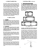
V. c - REPLACING THE GASKETS:
To remove the gasket to be replaced, grasp it firmly by
one corner and pull it out.  Before attempting to install
a new gasket, both the unit and the gasket itself must
be at room temperature.  Insert the four corners first
by using a rubber mallet (or hammer with a block of
wood).  After the corners are properly inserted, work
your way towards the center from both ends by gently
hitting with a mallet until the gasket is completely
seated in place (see figure 5 for proper gasket place-
ment).

NOTE: The gasket may appear too large, but if it is
installed as indicated above it will slip into place.

V. d - CLEANING THE EXTERIOR:
Exterior stainless steel should be cleaned with warm
water, mild soap and a soft cloth.  Apply with a damp-
ened cloth and wipe in the direction of the metal grain.

Avoid the use of strong detergents and gritty, abra-
sive cleaners as they may tend to mar and scratch the
surface.  Do NOT use cleansers containing chlorine,
this may promote corrosion of the stainless steel.

Care should also be taken to avoid splashing the unit
with water, containing chlorinated cleansers, when
mopping the floor around the unit.

For stubborn odor spills, use baking soda and water
(mixed to a 1 TBSP baking soda to 1 pint water ratio).

V. e - CLEANING THE INTERIOR:
For cleaning both stainless steel and anodized alumi-
num interiors, the use of baking soda as described in
section 

V. d

 is recommended.  Use on breaker strips

as well as door gaskets.  All interior fittings are re-
movable without tools to facilitate cleaning.

WARNING: DISCONNECT ELECTRICAL POWER
SUPPLY BEFORE CLEANING ANY PARTS OF THE
UNIT.

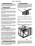
VI. MISC. OPERATIONS

VI. a - ADJUSTING THE SHELVES:
For shelves mounted on pins, first select the desired
location and remove the white plastic covers in the
interior back and sides by rotating them counter-clock-
wise.  Remove the shelf pins by rotating them counter-
clockwise.  Install the pins in the desired location by

-4-

IV. b - FREEZERS (cont

d):

trols function upon termination of a defrost cycle is
two-fold.  First, to prevent blowing warm air into the
food storage area.  Second, to prevent any conden-
sation on the defrost coil from being blown into the
food storage area.

The INTELA-TRAUL control is set from the factory to
terminate defrost at 20 minutes in the event of a sen-
sor failure.  This setting should never be tampered
with, without first consulting the factory.

IV. c - CONDENSATE REMOVAL:
Both refrigerator and freezer units are supplied with
an electric condensate evaporator for condensate re-
moval.

V. CARE & MAINTENANCE

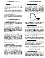
V. a - CLEANING THE CONDENSER:
The most important thing you can do to insure a long,
reliable service life for your Traulsen is to regularly
clean the condenser coil.

The condensing unit requires regularly scheduled
cleaning to keep the finned condenser clean of lint
and dust accummulation.  The INTELA-TRAUL con-
trol will notify you through a 

CLN-FIL

 message when

cleaning is necessary (see page 7).  Keeping the con-
denser clean allows the cabinet to operate more effi-
ciently and use less energy.

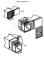
To  clean the condenser, first disconnect electrical
power to the cabinet and remove the front louver as-
sembly.  To remove this, follow the directions in sec-
tion VI. d - Step #1.  Once the screws are removed, the
panel can be removed allowing full access to the
powerpack.  Vacuum or brush any dirt, lint or dust
from the finned condenser coil, the compressor and
other cooling system parts.  If significant dirt is clog-
ging the condenser fins, use compressed air to blow
this clear.

Replace louver assembly, screws and caps.

V. b - HINGE REPLACEMENT:
Both the door and hinge can be easily removed from
the cabinet.  To remove the door, remove the plug at
the bottom of the top hinge.  Inside the hinge there is
a small screw which secures the door in place.  Re-
move this with a flat head screwdriver and the door
can then be lifted off the hinge.  To remove the door
half of the hinge from the door, lift off the hinge cover
and then remove the three Phillips head screws which
secure the hinge in place on the door.  To remove the
cabinet half of the hinge, remove the three Phillips
head screws which hold it in place.  To reassemble
the hinge reverse the previous procedure.

IV. OPERATION

 (continued)

V. CARE & MAINTENANCE

Fig. 5

Inside Door Panel

Gasket Assembly

Vertical Gasket

Retainer

Summary of Contents for UC Series

Page 1: ...er to the model and serial number found on the name tag affixed to the unit Should you need service however call us on our toll free number 800 825 8220 between 7 30 am and 4 30 pm CST Monday thru Friday It is our pleasure to help and assist you in every possible way Traulsen Co Inc OWNER S MANUAL Instructions for the installation operation and maintenance of all Traulsen UC Series Full Size Under...

Page 2: ... 10 g Customer Service Parameters Page 11 h Adjusting Thermostat Set Point High Page 11 i Adjusting Thermostat Set Point Low Page 12 j Changing The Temperature Scale Page 12 k Setting The 24 Hour Clock Page 13 l Setting The Date Page 14 m Setting Daylight Savings Time Page 14 n Starting A Manual Defrost Page 15 o Setting Defrost Lockouts Page 16 p Adjusting The Dewpoint Compensation Factor Page 17...

Page 3: ...all surfaces To remove the wooden pallet first if at all possible we suggest that the cabinet remain bolted to the pallet during all transportation to the point of final installa tion The bolts can then be removed with a 3 4 socket wrench Avoid laying the unit on its front side or back for removal of the pallet NOTE Traulsen does not recommend laying the unit down on its front side or back However...

Page 4: ...uring freezer defrost operation heat is confined to the coil enclosure to prevent any significant rise in temperature within the food zone The fan delay con 3 III INSTALLATION continued III d INSTALLING LEGS OR CASTERS cont d Please note that Traulsen units are not designed to be moved while on legs If the unit requires moving a pallet jack or forklift should be used to prevent dam age For install...

Page 5: ... warm air into the food storage area Second to prevent any conden sation on the defrost coil from being blown into the food storage area The INTELA TRAUL control is set from the factory to terminate defrost at 20 minutes in the event of a sen sor failure This setting should never be tampered with without first consulting the factory IV c CONDENSATE REMOVAL Both refrigerator and freezer units are s...

Page 6: ...3 Phillips head screws which secure each to the cabinet face Replace the hinges in their new loca tion and replace the screws Remove the hinge cover from the door half of the hinge by sliding it downwards Next remove the hinge hard ware from the door by removing the three 3 Phillips head screws which secure each to the door Turn the door around to its new position and replace the hinge hardware to...

Page 7: ...Fig 7b Fig 7a Remove Louver Assembly VI MISC OPERATIONS cont d 6 Fig 9 Removing Power Pack ...

Page 8: ...with HAACP standards Records alarm events Records diagnostic test of each sensor every 24 hours Records failed security attempts Records door open cycles Records defrost cycles refrigerator and freezer models only Note The 24 hour clock and the date must be set for the above information to be recorded at the correct time and date Communication Ability An RS485 port is available as a means of retri...

Page 9: ...en the unit regains power after an outage To turn off the audible alarm and or clear the visual text press the alarm cancel button You must reset the clock and date if you are using any defrost lockouts or are retrieving the information from the data storage memory See Setting The 24 Hour Clock page 12 and Setting the Date page 13 System Leak The audible alarm will sound and the display will read ...

Page 10: ...e order 3 DIGIT RED LED DISPLAY HOLDER CLIP 377 60038 00 EVAP COIL NOT USED CABINET AIR NOT USED TRANSFORMER RS485 DEFROST COMPRESSOR RELAY POWER LINE IN 2 DOOR HEATER EVAP BLOWER RELAY POWER IN LINE 1 INTELA TRAUL HORIZONTAL CONTROLLER 337 60062 00 HOLDER CLIP HORN DISCHARGE LINE COIL SENSOR 337 60071 00 refrigerator freezer only CABINET SENSOR 337 60069 00 DISCHARGE SENSOR 337 60072 00 refrigera...

Page 11: ...e following instructions Press the set button The display will read Customer Service Access Press the set button The display will show three zeros with the left zero flashing Press the set button The display will show three zeros with the center zero flashing Press the down arrow key to sequence through F E d C b A 9 8 7 etc When you reach A press set The display will show zero A zero with the rig...

Page 12: ... of the desired cabinet temperature range Typically freezers will range from 3 F to 0 F 19 C to 18 C and refrigerators will range from 36 F to 40 F 2 C to 4 C for this parameter setting This parameter is preset at the factory and does not have to be adjusted unless the customer chooses to do so Note Set Point Low and Set Point High cannot be set to the same temperature There will be at least 1 2 d...

Page 13: ...n the display shows the temperature you want press the set button The display will then read Thermostat Set Point High You can use the up or down arrow keys to scroll to the next parameter or press the alarm cancel button to exit VII j Changing The Temperature Scale The temperature scale determines if the temperature displayed will be in degrees Fahrenheit or degrees Celsius Follow the instruction...

Page 14: ... 5 00 a m H11 11 00 a m H17 5 00 p m H23 11 00 p m H06 6 00 a m H12 12 00 p m H18 6 00 p m H24 12 00 a m Follow the instructions to enter the customer access code on page 9 When the control displays Thermostat Set High press the down arrow key until the control display reads Clock Press the set button The display will show Hours The right two numbers will be flashing Use the arrow keys to set the ...

Page 15: ...ay is displayed press the set button The display will then read Thermostat Set Point High You can use the up or down arrow keys to scroll to the next parameter press the alarm cancel button to exit VII m SETTING DAYLIGHT SAVINGS TIME This parameter is preset at the factory to automatically adjust the 24 hour clock for Daylight Savings Time Follow the instructions to enter the customer access code ...

Page 16: ...w key YES The display will show Press the set button The display will then read Thermostat Set Point High You can use the up or down arrow keys to scroll to the next parameter or press the alarm cancel button to exit The defrost icon will be lit and the display will read when the unit is in defrost VII INTELA TRAUL continued 15 VII n STARTING A MANUAL DEFROST CYCLE SET SET NOTE Traulsen refrigerat...

Page 17: ... 6 00 a m 120 12 00 p m 180 6 00 p m 240 12 00 a m 063 6 30 a m 123 12 30 p m 183 6 30 p m 243 12 30 a m 070 7 00 a m 130 1 00 p m 190 7 00 p m 010 1 00 a m 073 7 30 a m 133 1 30 p m 193 7 30 p m 013 1 30 a m 080 8 00 a m 140 2 00 p m 200 8 00 p m 020 2 00 a m Denotes not available A lockout can not be programmed to start at 12 00 am or 12 30 am due to conflicts with other internal programs The de...

Page 18: ...meter or press the alarm cancel button to exit 17 VII INTELA TRAUL continued SET SET VII q SETTING THE AUDIBLE ALARM STYLE This parameter will allow the customer to turn on off the audible alarm feature on the INTELA TRAUL control The audible alarm is preset from the factory to OFF The customer can choose between an audible alarm that sounds for 3 seconds then automatically turns off or a continuo...

Page 19: ...s to enter the customer access code on page 9 When the control displays Thermostat Set Point High press the DOWN arrow key unit the display reads Evaporator Coil Sensor or Disharge Line Sensor or press the SET button The display will read Thermostat Set Point High Press the UP or DOWN arrow keys to scroll through the parameters or press the ALARM CANCEL button to exit VII INTELA TRAUL continued 18...

Page 20: ...antity of warm food has recently been added or the door was kept open for a long period of time in both cases allow adequate time for the cabinet to recover its normal operating temperature c INTELA TRAUL setting too high readjust per instructions on page 11 4 Food compartment is too cold a Perhaps a large quantity of very cold or frozen food has recently been added Allow adequate time for the cab...

Page 21: ... of said control which proves to be defective Inspection by the TRAULSEN Service Department of parts claimed defective shall be final in determining warranty status The warranty is to include repair or exchange of any defective In Warranty control or part s of said control for Part s Any TRAULSEN INTELA TRAUL supplied part s found to be defective Labor The labor charges from a TRAULSEN Certified S...

Page 22: ...uver assembly for all UL models Shelf Pin 344 24759 00 Replacement shelf pin Side Panel Exterior Stainless steel exterior side panel X OTHER X a SERVICE INFORMATION Before calling for service please check the following Is the electrical cord plugged in Is the fuse OK or circuit breaker on Is the power switch ON If after checking the above items and the unit is still not operating properly please c...

Page 23: ...age 6 E F G Gaskets 5 H Hinge 4 5 I Internal Time Clock 6 INTELA TRAUL 3 4 5 6 17 J K L Legs 2 Louver Assembly 4 5 M Manual Defrost Cycle 14 N O P Power Supply 3 R Return Authorization 2 Room Temperature Offset 16 S Serial Tag 1 Shelf Pins 2 Shelves 2 5 Smart Recovery 6 T Thermostat Set Point High 10 Thermostat Set Point Low 11 U V Vinyl Protective Covering 2 W Warranty 19 Warranty Registration 21...

Page 24: ...Traulsen Co Inc 4401 Blue Mound Road Fort Worth TX 76106 Phone 800 825 8220 Fax Svce 817 740 6757 Website www traulsen com HOURS OF OPERATION Monday thru Friday 7 30 am 4 30 pm CST Quality Refrigeration ...

Reviews: