Transmitter Solutions Wi-Enterprise Installation & User Manual Download Page 8

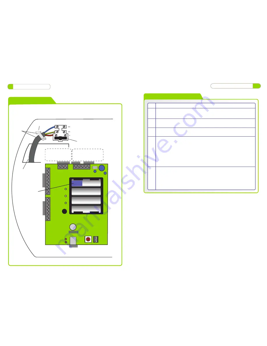
Note : Used ONLY for

Wired 485 Network

Connections.

A

B

COM

TX

RX

PC Network

PC Direct

PC Network Connections

can be used for multiple

controllers See page

10 for wiring

Wiring Diagrams

 8

Wiring Diagrams

Door Network

A

B

COM

1 2 3 

4

OF
F

O

N

TCP_IP

3V Lithium

Inpu

ts/outpu

ts

IP1
IP2
0V
IP3
IP4
12V
OP1
OP2

OP3
OP4
0V
VOUT
DAT
CLK
SEN

Inpu

ts/outpu

ts

Cable Tie

Fuse Rating : 230VAC 315mA

Warning : Installation should only be carried out

by a suitably qualified person only.

Cable Tie

retaining

clips

Main Input Cable

230VAC

Neutral

Earth
Live

Remove Battery Tab

Pull

 21

Operation Instructions

Enrolling User FingerPrints

Step   Description

           Note: Make sure the USB Fingerprint reader is attached to the PC

   1.     On the Users Tab , Select a User for fingerprint enrolment

   2.    Click on the ‘Fingerprints’ button.

   3.     Click on ‘+’ button to begin and place finger on the enrolment reader. An
           image of the fingerprint will appear on the screen. Ensure that the image
           quality is good and a value of at least 90% is achieved. Refer to section
           ‘Finger Placement’ for correct finger placement and example of good
           quality image. Repeat this process if this is not achieved on first attempt.
           Two fingerprint templates can be saved for each user.

   4.     Click ‘Save’ using a good quality template only. Poor Quality templates can
           lead to false rejections later when trying to gain access

Summary of Contents for Wi-Enterprise

Page 1: ...Diagrams 9 8 System Overview 4 Installation Instructions 12 Network Diagrams Wiring Diagrams 21 Fingerprint Enrollment Operation Instructions Wi Enterprise Controller www transmittersolutionssmart com...

Page 2: ...e IP 67 IP65 on Wi Bio Dimensions Flush Mount W 87mm D 21mm H 119mm Surface Mount W 87mm D 35mm H 119mm Technical Specs Wi Enterprise Door Controls Features Doors controlled Users User Groups Time Zon...

Page 3: ...etting up TCP IP 12 7 Phase 1 Setting up the Controller via the PC application 14 8 Phase 2 Configuring the Controller via the PC application 15 9 Phase 3 Defaulting Door Controls 16 10 Phase 4 Enroll...

Page 4: ...retaining screw to remove cover pull out on right and slide left to remove cover pull out on right and slide left to remove cover pull forward on right and slide left 4 Installation Diagrams Incorrec...

Page 5: ...rity Type screws rear tamper switch cable entry cable entry cable entry cable entry spare cap access to rear void for wiring spirit level mains pcb mount hole mount hole mount hole 5 Installation Diag...

Page 6: ...ss A B on the last Door Control in the chain Place a 120ohm Termination Resistor across A B on the Controller TCP IP connection to Controllers or RS485 Network to Controllers Max number of Controllers...

Page 7: ...munication range depends on building shape and construction methods used 7 System Overview Note If using a single Controller an RS232 cable may be used Max cable length 10 meters Correct Finger Placem...

Page 8: ...tion Instructions Enrolling User FingerPrints Step Description Note Make sure the USB Fingerprint reader is attached to the PC 1 On the Users Tab Select a User for fingerprint enrolment 2 Click on the...

Page 9: ...s Select DoorGroups and Timezones from the drop down menus to add to the current UserGroup 2 Timezones are the periods of time for each day of the week that access will be granted Select times and tic...

Page 10: ...ss 2 Set SW2 ON Address 3 Set SW3 ON Controller 1 Controller 2 Set Baud Rate to 19200 Daisy Chain each controller A B 0V 1 2 3 4 Controller 3 OFF ON 1 2 3 4 OFF ON 1 2 3 4 OFF ON Phase 5 Configuring U...

Page 11: ...All dip switches ON The dip switches s should then be set to the controller address as shown above in section Setting the controller address 18 Operation Instructions Phase 4 Enrolling Door Controls...

Page 12: ...the next available address then all Door Controls will beep at the same time with 2 beeps This is basically saying that any door can be assigned to this address it s up to the installer to decide whic...

Page 13: ...and enter the new IP address to allow the application to communicate with the Controller Note Reset the IP address on your PC to its original setting for your LAN 13 Operation Instructions 16 Operati...

Page 14: ...ing up DHCP or Static IP addresses E The Controller icon will change colour from gray off line to green on line to show that the Controller is communicating with the application F Go to the Current Ev...

Reviews: