7
6: oPeRATIoN
6.1 General Information:
The CNT 10 L Tester performs it`s tests when the
single button on it`s front panel is pressed and
released. 6 Status LEDs indicate the condition of the
cable being tested, as well as informing the user that
Power is turned on, and that the battery is good (or
bad). 8 additional connection LEDs light to indicate
that specific wires in a cable are connected.
Note: Only one cable can be tested at a time. i.e.
A BNC cable and an RJ-45 cable cannot be tested
simultaneously.
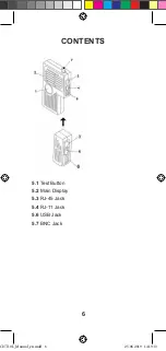
6.2 The MAIN and ReMoTe unit:
The CNT 10 L Tester consists of a Main unit and a
Remote unit. The Remote unit stores conveniently
on the bottom of the Main unit. lt can be removed or
replaced by sliding it from left to right or right to left
respectively. Use care when removing or replacing
the Remote. Some of the plastic edges are a little
sharp.
The Remote is often attached to the Main unit when
storing, when transporting, or when patch cables are
being tested. The Remote is removed from the Main
unit when an installed (in wall, ceiling, etc.) cable is
being tested.
6.3 Testing Patch cables:
„Patch“ cables have both ends accessible at the
same location. Usually, but not always, these cables
are less than 25ft in length, and are not installed in a
wall or ceiling. Since both ends are accessible, one
end can be plugged into the 5 in 1 Main unit, and
one end into the Remote unit. It is not necessary to
remove the Remote unit from its docked position on
the Main unit.
6.4 Testing lnstalled cables:
To test cables installed in ceilings or walls, or in
applications that prevent the ends from being in the
same location, the Remote can be detached from
the Main unit. Once detached, the Remote can
be attached to one end a cable, and the Main unit
attached to the other end of the cable. These ends
are often in different rooms and on different floors of
a building.
CNT10L_Manual_en.indd 7
25.06.2019 14:19:13


