


Part Number
Optional Accessories
(sold separately)
SPS-1872-SA
Optional External Power Supply; 18-72VDC Stand-Alone
Output: 12.6VDC, 1.0 A
SPS-1872-PS
Optional External Power Supply; 18-72VDC Piggy-back;
Output: 12.6VDC, 1.0 A
E-MCR-04
12-Slot Device Rack
(includes universal internal power supply)
17 x 15 x
5 in.
(432 x 381 x 127 mm)
WMBL
Optional Wall Mount Brackets; 4.0 in.
(102 mm)
WMBV
Optional Vertical Mount Bracket; 5.0 in
. (127 mm)
WMBD
Optional DIN Rail Mount Bracket; 5.0 in.
(127 mm)
WMBD-F
Optional DIN Rail Mount Bracket (flat); 3.3in
. (84 mm)
2
24-hour Technical Support: 1-800-260-1312 -- International: 00-1-952-941-7600
SSDTF30xx-11x
*
Typical maximum cable distance. Actual distance is dependent upon the physical
characteristics of the network. (TX) = transmit (RX) = receive
Remote Management
The SSDTF30xx-11x stand-alone Device can be remotely managed by the
CSDTF30xx-11x, the chassis version of the Device.
For example, a local CSDTF3011-115 device
(that is installed in a managed Transition
Networks PointSystem™ chassis)
is connected, via fiber, to a remote SSDTF3011-115
device. An example of a managed single-fiber network has a local CSDTF3029-115
device connected, via fiber, to a remote SSDTF3029-116.
Note:
In a managed network, both the local and remote Devices must be set to
“software” mode.
For more information, see the SNMP section in the CSDTF30xx-11x user’s guide
on-line at: www.transition.com.
Part Number
Port One -
Copper
Port 2 -
Simplex Fiber Optic
SSDTF3029-115 and SSDTF3029-116 are intended to be installed
in the same network where one is the local device and the other
is the remote device.
SSDTF3029-117 and SSDTF3029-118 are intended to be installed
in the same network where one is the local device and the other
is the remote device.
SSDTF3029-
115
75 ohm BNC coax
100 m
(328 ft.)*
SC, 1310 mn (TX)/1550 nm (RX)
single mode, 20 km
(12.4 miles)*
SSDTF3029-
116
75 ohm BNC coax
100 m
(328 ft.)*
SC, 1550 mn (TX)/1310 nm (RX)
single mode, 20 km
(12.4 miles)*
SSDTF3029-117
75 ohm BNC coax
100 m
(328 ft.)*
SC, 1310 mn (TX)/1550 nm (RX)
single mode, 40 km
(24.8 miles)*
SSDTF3029-118
75 ohm BNC coax
100 m
(328 ft.)*
SC, 1550 mn (TX)/1310 nm (RX)
single mode, 40 km
(24.8 miles)*
[email protected] -- Click the “Transition Now” link for a live Web chat.
3
Installation
CAUTION: Wear a grounding device and observe electrostatic discharge precautions
when setting the jumper and switches. Failure to observe this caution could result in
damage to, and subsequent failure of, the Device.
Set the Hardware/Software Jumper
The jumper is located on the circuit board inside the Device housing.
Hardware
The Device mode is determined by the switch settings.
Software
The Device mode is determined by the
most-recently saved, on-board
microprocessor settings.
To set the jumper:
1.
Using a small screwdriver, remove the four (4)
screws that secure the cover and carefully
remove the cover from the Device.
2.
Locate the jumper on the circuit board.
3.
Using small needle-nosed pliers or similar device, move the jumper to the
desired position.
(Refer to the above drawing.)
4.
Carefully replace the cover on the Device and replace the four (4)
screws that secure the cover to the Device.
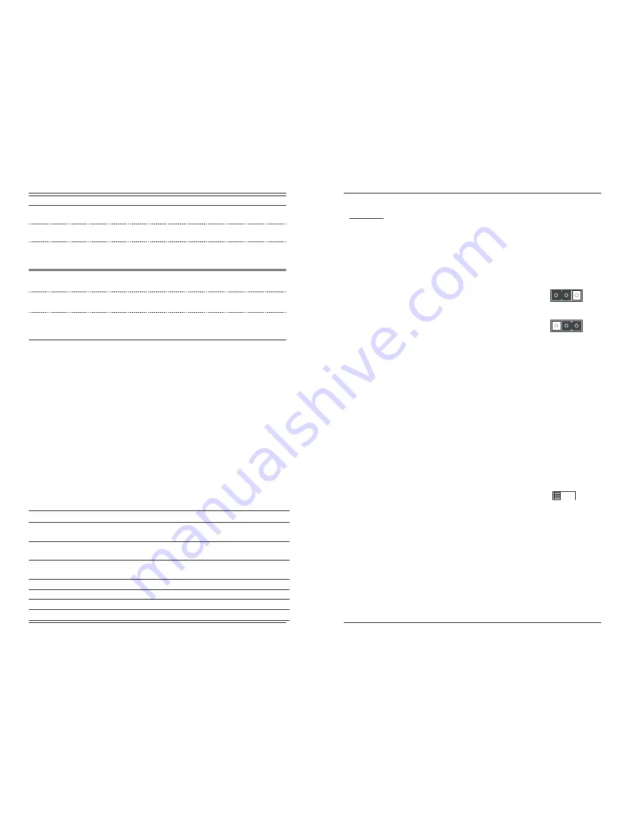
Hardware Mode
Software Mode
H
H
S
S
Set the Loop-Back Switch
Hardware Mode:
The loop-back switch is located on the front panel of the Device and is used for
installation and network debugging procedures.
To set the switch, use a small flat-blade screwdriver or a
similar device
(see the drawing to the right)
.
CL (
Coax loop-back)
Enable loop-back on the local coax interface.
--
(Center Position)
Normal operation.
FL
(Fiber loop-back)
Enable loop-back on the local fiber interface.
Software Mode:
If both Devices are under software control, the network administrator can initiate
the loop-back test function on the coax interface
(local or remote)
or on the fiber
interface
(local or remote).
These four loop-back test scenarios are described in
detail in this manual.
CL
FL


