background image

6

24-Hour Technical Support: 

800-260-1312

-- International: 

952-941-7600

SPS-1872-xx

GND

-

+

- +

_____

_

___

___

___

___

___

___

1

2

3

INPUT
POWER:

1

2

3

SPS-1872-xx

External Power Source

Installation 

-- Continued

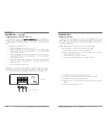
Supplying Power to the SPS-1872-xx

CAUTION:  The power source MUST BE TURNED OFF when connecting it to
the SPS-1872-xx external power supply.  Failure to observe this caution could
result in damage to, and subsequent failure of, the SPS-1872-xx and any attached
device.

To supply power to the SPS-1872-xx:

1.

Ensure that external power source is truned OFF.

2.

Connect the positive (+) terminal of the power source to the positive
terminal on the SPS-1872-xx

(marked with a “3”).

Turn the terminal

screw clockwise to secure it.

3.

Connect the negative (-) terminal of the power source to the negative
terminal on the SPS-1872-xx 

(marked with a “2”)

.  Turn the terminal

screw clockwise to secure.

4.

Connect the ground terminal of the power source to the ground terminal
on the SPS-1872-xx 

(marked with a “1”).

Turn the terminal screw

clockwise to secure.

5.

Power on the external power source.

WARNING:  The SPS1872 must be attached to a limited current circuit with a
non-hazardous energy level of less than 240VA and be located in a restricted
access area. Failure to observe this warning could result in an electrical shock.

[email protected]

-- Click the 

“Transition Now”

link for a live Web chat.

7

Maintenance

Replacing the Fuse 

CAUTION:  The external power source MUST BE POWERED OFF when
replacing the fuse to the SPS-1872-xx external power supply.  Failure to observe
this caution could result in damage to, and subsequent failure of, the SPS-1872-
xx and any attached device.

NOTE: 

Replace the fuse only with one of the same size and rating.  

To replace the fuse in the SPS-1872-xx external power supply:

1.

Ensure that the external power source is turned OFF.

2.

Remove and retain the four (4) screws that secure the cover to the SPS-
1872-xx external power supply.

3.

Carefully lift the cover from the SPS-1872-xx.

4.

Locate the fuse on the SPS-1872-xx 

(see the picture below).

5.

Carefully remove the fuse the from the fuse holder.

6.

Install a same size and rating replacement fuse in the fuse holder.  

7.

Carefully slide the cover onto the SPS-1872-xx.

8.

Replace the four (4) retained screws that secure the cover to the SPS-
1872-xx.  

9.

Power on the external power source.

Summary of Contents for SPS-1872-CC

Page 1: ...and industrial applications The 24 30 VRMS input allows for installation of the SPS 1872 xx in remaining industrial applications as well as HVAC and building control environments The piggy back feature of the SPS 1872 CC SPS 1872 PS and SPS 1872 DPS allows it to physically attach to the media converter chassis and eliminate the power cable between the power supply and the media converter User s Gu...

Page 2: ...re to observe this caution could result in damage to and subsequent failure of the power supply module WARNING The SPS1872 must be attached to a limited current circuit with a non hazardous energy level of less than 240VA and be located in a restricted access area Failure to observe this warning could result in an electrical shock techsupport transition com Click the Transition Now link for a live...

Page 3: ...he two devices are connected The screw holes on the left and right sides should align 3 Secure the two devices together by replacing the two screws on either side of the SPS 1872 PS 4 24 Hour Technical Support 800 260 1312 International 952 941 7600 SPS1872 xx SPS 1872 PS TN PointSystem media converter SPS 1872 CC TN Conversion Center media converter techsupport transition com Click the Transition...

Page 4: ...RNING The SPS1872 must be attached to a limited current circuit with a non hazardous energy level of less than 240VA and be located in a restricted access area Failure to observe this warning could result in an electrical shock techsupport transition com Click the Transition Now link for a live Web chat 7 Maintenance Replacing the Fuse CAUTION The external power source MUST BE POWERED OFF when rep...

Page 5: ...d according to Belcore 834 000 hours with typical load at 50 C ambient temperature calculated according to MIL HDBK 217F Environment Tmra 0 to 50 C 32 to 122 F Storage Temp 20 to 85 C Humidity 5 to 95 non condensing Altitude 0 to 10 000 feet Manufacturer s rated ambient temperature Warranty Lifetime techsupport transition com Click the Transition Now link for a live Web chat 9 Technical Specificat...

Page 6: ...e European Parliament and of the Council of 27 January 2003 Transition Networks will accept post usage returns of this product for proper disposal The contact information for this activity can be found in the Contact Us portion of this document CAUTION RJ connectors are NOT INTENDED FOR CONNECTION TO THE PUBLIC TELEPHONE NETWORK Failure to observe this caution could result in damage to the public ...

Page 7: ...ir respective owners Copyright Restrictions 2003 2005 Transition Networks All rights reserved No part of this work may be reproduced or used in any form or by any means graphic electronic or mechanical without written permission from Transition Networks Printed in the U S A 33266 E ...

Reviews: