
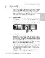


10
CPSMC13xx-100 PointSystem
™
Chassis
slide-in-modules
24-hour Technical Support:
1-800-260-1312
-- International:
00-1-952-941-7600
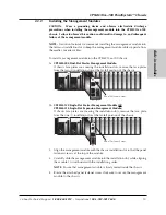
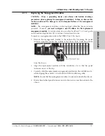
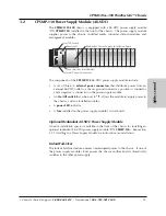
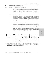
2.2.2
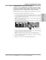
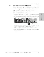
Installing the Management Modules
CAUTION: Wear a grounding device and observe electrostatic discharge
precautions when installing the management module into the CPSMC13xx-100
chassis. Failure to observe this caution could result in damage to, and subsequent
failure of, the management module.
NOTE:
Transition Networks recommends installing the management module into
the left-most installation slot to keep the management module cables separate from
the media converter cables.
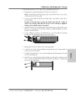
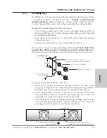
To install a management module into the CPSMC13xx-100 chassis:
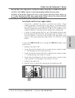
1a.
CPSMM-200 Dual-Slot Master Management Module:
If chassis face plates are covering the installation slots, remove the face plates
from the two (2) installation slots at the far-left position of the chassis.
1b.
CPSMM-120 Single-Slot Master Management Module OR
CPSMM-210 Single-Slot Expansion Management Module:
If chassis face plates are covering the installation slots, remove the face plate
from the one (1) installation slot at the far-left position of the chassis.
2. Align the management module with the chassis installation slot so that the panel
fastener screw is at the top of the module.
3. Carefully slide the management module into the installation slot, while aligning
the module’s circuit board with the installation guides.
NOTE:
Ensure that management module is firmly seated inside the chassis.
4. Rotate the attached panel fastener screw clockwise to secure the management
module to the chassis.
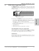
I
0
TERM
INIT
RX
TX
LNK
PWR
CPSMM120
SERIAL
10BASE-T
R
E
S
E
T
I
0
MCCM10
MGMT MASTER
DB-9
12C
12C-1
TERM
INIT
RX
TX
LNK
PWR
RESET
DB-9
Panel Fastener Screw
I
0
TERM
INIT
RX
TX
LNK
PWR
CPSMM120
SERIAL
10BASE-T
R
E
S
E
T
I
0
RX
TX
LNK
PWR
RESET
Panel Fastener Screw