
Ethernet™
10BaseT
Micro-™
The TRANSITION Networks Ethernet 10BaseT Micro- (E-TBT-MC01(D)) provides a simple
means for connecting to an Ethernet network. The Micro- is an AUI to RJ-45 10BaseT
transceiver.
INSTALLATION INSTRUCTIONS
1.
Connect the Micro-ceiver to the AUI port on the Ethernet card or repeater (The Micro-
ceiver can be attached to an AUI cable which is connected to a card or repeater, maximum AUI
cable distance 50 meters or 165 feet, or can be connected directly to a PC ethernet card.)
NOTE: The two active pairs in a
10BaseT network are pins 1 & 2 and
pins 3 & 6. Use only dedicated wire
pairs (such as blue/white &
white/blue, orange/white &
white/orange) for the active pins.
2.
Connect one end of the straight through male/male10BaseT RJ-45 cable to the Micro-
and the other end to the network via a hub or wall outlet.
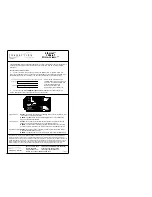
Off
SQE
RX
TX
Link
Power
Collision
Jabber
Pol
On
Link Sense
-3dB Squelch
networks
Mpls, MN 55344
T R A N S I T I O N
Ethernet™
10BaseT
Micro-ceiver™
SQE Function:
Enable - The SQE switch should be enabled (ON) when the Microceiver™ AUI
is connected to a DTE or workstation
Disable - The SQE switch should be disabled (OFF) when connected to the
AUI port of an Ethernet repeater.
Link Function:
Enable - The link switch in the (ON) position sends a link pulse through the
segment. This pulse is present only for current 10BaseT devices.
Disable - The link switch in the (OFF) position turns the link pulse off. In this
position the Micro-ceiver AUI can communicate with pre-10BaseT products.
Squelch Function: Enable - The Squelch switch in the (ON) position boosts the signal to fuction
with SHIELDED twisted pair wiring.
Disable - The Squelch switch in the (OFF) postion is for use with standard UTP.
FCC APPROVAL: This equipment has been tested and found to comply with the limits for a class A digital device,
pursuant to part 15 of the FCC rules. These limits are designed to provide reasonable protection against harmful
interference when the equipment is operated in a commercial environment. This equipment generates, uses, and can
radiate radio frequency energy and, if not installed and used in accordance with the instruction manual, may cause
harmful interference to radio communications. Operation of this equipment in a residential area is likely to cause
harmful interference, in which case, the user will be required to correct the interference at his own expense.
Minneapolis, MN 55344 USA
phone 612-941-7600
toll free 800-LAN-WANS (800-526-9267)
fax 612-941-2322
bulletin board 612-941-9304
[email protected] [email protected]
toll free tech support USA 800-260-1312
7310.C
Pin configuration for the RJ45 straight through cable assembly, male/male
Twisted pair #1
Twisted pair #2
1
2
3
6
1
2
3
6


