CPSMP-210 48VDC and CPSMP-220 24VDC Power Supplies
4
24-Hour Technical Support: 1-800-260-1312 -- International: 00-1-952-941-7600
Notices
•
The CPSMP-210 48VDC and CPSMP-220 24VDC power supplies must be
installed by qualified technical personnel only. Transition networks assumes no
responsibility for the improper installation, set up or use of these power supplies.
•
The information in this user’s guide is subject to change. For the most up-to-date
information, see the user’s guide on-line at www.transition.com.
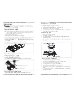
Figure 1: Power Supply Components
Description
Transition Networks’ CPSMP-210 48VDC and CPSMP-220 24VDC power supplies
can deliver power or provide optional, redundant DC power to the CPSMC18xx-xxx
and the CPSMC19xx-100 PointSystem chassis.
Power supply component identification
See Figure 1:
•
Power ON LED
(green)
•
External power connector
(terminal block)
for connecting an external power
source to the power supply
•
Fuse
(on the power supply board)
•
ON/OFF switch, when in the ON position power is supplied to the PointSystem
chassis
•
Four-position configuration switch
(located on IFO board)
sets power-supply
functionality
•
Chassis ground screw
•
Fan
•
Handle for installing and removing the power supply
Power ON LED
(green)
(holder not shown)
Fuse
Four-Position
Configuration Switch
ON/OFF Switch
± Power-Lead Terminal
Block Connectors
Grounding Screw
Fan
Instant Failover (IFO)
Board
Power Supply Board
Handle
[email protected] -- Click the “Transition Now” link for a live Web chat.
5
Installation
I
MPORTANT
•
All installation and service must be performed by qualified personnel only.
•
Read and follow all CAUTION and WARNING notices, instructions marked on
the product, including this manual.
The CPSMP-210 and CPSMP-220 power supply can replace an existing DC power
supply. Either can be installed as the redundant power supply in an AC- or DC-
powered PointSystem chassis.
CAUTION: While installing or servicing the power supply, wear a grounding
device and observe all electrostatic discharge precautions. Failure to observe this
caution could result in damage to, or failure of the power supply.
Configuration switch
Located on the IFO board, the power supply has a four-position configuration switch,
shown in Figure 2.
Configuration switch-position explanations
The management/manual switch establishes PointSystem software or manual control
of master/slave switch settings for the power supply.
•
When the management/manual switch is in the
management
position, power-
supply configuration can be set to master or slave via software.
•
When the management/manual switch is in the
manual
position, power-supply
configuration is set manually to master or slave and cannot be changed via
software.
•
When the master/slave switch is in the
master
position, the power supply is the
primary power source for the chassis.
•
When the master/slave switch is in the
slave
position
(additional power supply)
,
the power supply is used for redundancy
(failover)
purposes, in the event of a
master power-supply failure.
Four-Position Configuration Switch
Instant Failover (IFO) Board
Power Supply Board
Management
Manual
Master
Slave
!
Figure 2: Configuration Switch Location
CPSMP-210 48VDC and CPSMP-220 24VDC Power Supplies


