Transition Networks BFFG1XXX-1XX User Manual Download Page 15

Transition Networks 


Section I:  FBRM/BFFG Product Description


Hardware description, 

continued 


Front panel 
CFBRM Gbit 

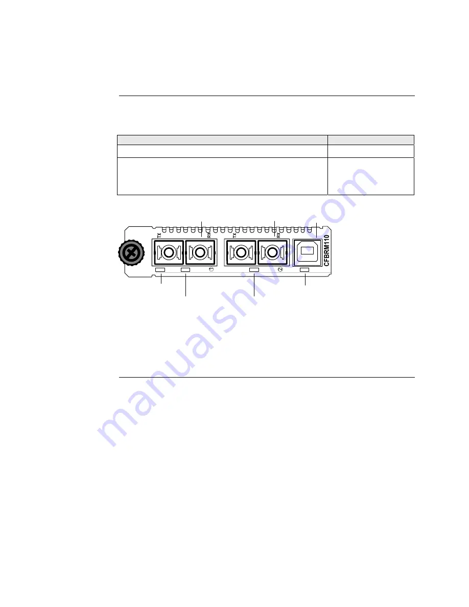
The front panel of the CFBRM13xx-1xx Devices has the following ports and LEDs: 


Ports 

Front Panel LEDs 


Power 

(one) 

One 100 Base-T 


Fiber-Port Link 

(one)

One 1000Base-FX/LX/BX fiber either SC or ST connectors 


Fiber-Port Link 

(one)

One USB  


USB 

(one) 


Fiber Link

LED

Fiber Link

LED

Power

LED

USB LED

SC Connector

Fiber

SC Connector

Fiber

USB Port

USB

LNK

PWR

LNK

100Base-T

1000Base-X


Figure 3:  Chassis CFBRM13xx-1xx Device Front Panel 


Note:

  The LEDs and ports are the same on the SFBRM13xx-1xx standalone 

models. 


Continued on next page 

24-Hour Technical Support:   1-800-260-1312   International: 00-1-952-941-7600 

7


Summary of Contents for BFFG1XXX-1XX

Page 1: ... X 1000Base X USB USB LNK LNK PWR DPX 1000Base X 1000Base X USB USB LNK LNK PWR 1 2 LACT FD LACT FD PWR USB USB DPX 10 100Base TX 100Base FX CFBRM LACTPWR USB 10 100 1000 1000Base X CBFFG LACT PWR FBRM1xxx 1xx BFFG1xxx 1xx Chassis Stand Alone Remotely Managed Devices Manual 33345 Revision D ...

Page 2: ......

Page 3: ......

Page 4: ......

Page 5: ...port 29 Section live 32 Initial Device Setup 32 USB CLI access 33 Initial Device setup via USB CLI 35 Initial Device setup via telnet directly to Device 38 Initial Device setup via chassis agent MMU web based 41 Initial Device setup IP web based directly to Device 44 Sections V 49 Device Management 49 SNMP IP based management 50 Device management via chassis agent MMU web based 53 Device managemen...

Page 6: ...s 102 Conformity declaration 103 Warranty 105 Compliance information 107 Appendix A 109 FBRM BFFG Part Numbers 109 FBRM copper to fiber part numbers 109 FBRM fiber to fiber part numbers 112 BFFG copper to fiber part numbers 115 BFFG fiber to fiber part numbers 116 Appendix B 120 FBRM BFFG Technical Specification 120 Specifications notices and warnings 120 Appendix C 122 Device Commands Description...

Page 7: ...ed or used in any form or by any means graphic electronic or mechanical without written permission from Transition Networks Printed in the U S A About this manual This manual is designed to help you find the information you need quickly It is structured as follows Table of Contents TOC Section TOC Shows all the major topics in the section Side Headings Shows all the sub topics on each page Index 2...

Page 8: ... Ethernet USB RS232 RS422 RS485 DS1 DS3 Video Coax etc are intended to be connected to intra building inside plant link segments that are not subject to lightening transients or power faults Copper based media ports e g Twisted Pair TP Ethernet USB RS232 RS422 RS485 DS1 DS3 Video Coax etc are NOT to be connected to inter building outside plant link segments that are subject to lightening DO NOT in...

Page 9: ...are the topics Topic See Page General description 2 Product features 3 Management methods 4 Hardware description 5 FBRM BFFG13xx 1xx fiber to fiber gigabit models 13 Redundant SFBRM1040 140 models 15 24 Hour Technical Support 1 800 260 1312 International 00 1 952 941 7600 1 ...

Page 10: ...ration and Maintenance per the IEEE 802 3ah 2004 standard Standalone Devices can also be managed via IP Web based or Telnet What is OAM These Devices implement the IEEE 802 3ah standard or OAM in the Ethernet first mile OAM is a group of network management functions that provide network fault indications performance information data and diagnosis These Devices implement remote management via OAM a...

Page 11: ... speed non gigabit models only Force half or full duplex Pause capability Automatic firmware upgrade via OAM Forwards all IEEE multicast frames including STP LACP LAMP Enable disable USB port access Enable disable SNMP queries Enable disable system level IP management or on a per port basis IEEE 802 1q VLAN virtual local area network Management VLAN for all management frames IEEE 802 1x port based...

Page 12: ...the Device IP address as shown as follows Telnet nnn nnn nnn nnn represents Device IP address MMU The MMU Management Module Unit is the heart of the Point System chassis management capability It has the ability to monitor and manage all its installed Devices The MMU communicates through the CLI presented at the serial port or through SNMP Telnet CLI and Web interface available via the Ethernet por...

Page 13: ...Power one One RJ 45 auto sensing of 10Base or 10 100Base TX UTP connections RJ 45 port two One 100Base FX LX BX fiber either SC or ST connectors LACT one DPX one One USB USB one Figure 1 Chassis CFBRM10xx 1xx Device Front Panel Note The LEDs and ports are the same on the SFBRM10xx 1xx standalone models Continued on next page 24 Hour Technical Support 1 800 260 1312 International 00 1 952 941 7600 ...

Page 14: ...l of the CFBRM 1040 140 Devices has the following ports and LEDs Ports Front Panel LEDs Power one 100Base FX SFP port Link Active 10 100 Base T copper port Speed Duplex one One USB USB one Figure 2 CFBRM1040 100 Front Panel Note The LEDs and ports are the same on the SFBRM1040 140 standalone models Continued on next page 6 ...

Page 15: ...ink one One 1000Base FX LX BX fiber either SC or ST connectors Fiber Port Link one One USB USB one Fiber Link LED Fiber Link LED Power LED USB LED SC Connector Fiber SC Connector Fiber USB Port USB LNK PWR LNK 100Base T 1000Base X Figure 3 Chassis CFBRM13xx 1xx Device Front Panel Note The LEDs and ports are the same on the SFBRM13xx 1xx standalone models Continued on next page 24 Hour Technical Su...

Page 16: ... CBFFG10xx 1xx Devices has the following ports and LEDs Ports Front Panel LEDs Power one 1000Base SX LX BX fiber SC port Link Active 10 100 1000Base T copper port Speed Duplex one One USB USB one Figure 4 CBFFG10xx 1xx Device Front Panel Note The LEDs and ports are the same on the SBFFG10xx 1xx standalone models Continued on next page 8 ...

Page 17: ...Power one 1000Base SFP port Link Active 10 100 1000Base T copper port Speed Duplex one One USB USB one USB 10 100 1000 1000Base X Speed Duplex Link USB LED Power Link Active SFP Port USB Port RJ45 Port Figure 5 CBFFG1040 1xx Device Front Panel Note The LEDs and ports are the same on the SBFFG1040 1xx standalone models Continued on next page 24 Hour Technical Support 1 800 260 1312 International 00...

Page 18: ...BFFG13xx 1xx Devices has the following ports and LEDs Ports Front Panel LEDs Power one Two 1000Base FX LX BX fiber either SC or ST connectors Fiber Port Link two Duplex one One USB USB one Figure 6 Chassis CBFFG13xx 1xx Device Front Panel Note The LEDs and ports are the same on the SBFFG13xx 1xx standalone models Continued on next page 10 ...

Page 19: ...40 redundant Devices has the following ports and LEDs Ports Front Panel LEDs Power one 1000Base SX LX SFP ports 2 and 3 Link Active Duplex 10 100 1000Base T copper port 1 Speed Duplex one One USB USB one Figure 7 CBFFG1040 140 Device Front Panel Continued on next page 24 Hour Technical Support 1 800 260 1312 International 00 1 952 941 7600 11 ...

Page 20: ...standalone On the standalone SFBRM and SBFFG Devices only the rear panel consists of a power barrel connector for connecting power via a power adaptor See Figure 8 Figure 8 SFBRM SBFFG 1xxx 1xx Device Real Panel Standalone Only Note The Point System chassis powers the CFBRM and CBFFG chassis Devices 12 ...

Page 21: ...configured See Tables 1 and 2 Table 1 FBRM13xx 1xx 100Base FX to 1000Base X Device Port Configuration Port 1 100Base FX Default setting 100Mbs and full duplex FEFI Far end fault indication is configurable Port 2 1000Base X Default Auto Negotiation enabled OAM enabled and in Active Mode if chassis Device passive if standalone Table 2 BFFG13xx 1xx 1000Base X to 1000Base X Device Port Configuration P...

Page 22: ...he explanation that follows Figure 9 Connectivity Scenarios Connection scenario explanation In Figure 9 P2 of the active local peer in both scenarios is OAM enabled and Active by default To manage the remote passive peer via OAM configure P1 of the active local peer as follows Enable OAM Select Active mode If the connection to the passive remote peer is made thru P2 of the active local peer OAM oc...

Page 23: ...rt in Redundancy Mode and Port 2 the primary goes down the following will happen Stage Description A All Physical layer and OAM configurations of Port 2 will be applied to Port 3 B Port 2 is disabled and Port 3 initialized to take over C An SNMP trap is sent indicating that the ports have switched D OAM reinitializes resets all OAM counters and event logs E All the dynamic MAC entries in the ATU a...

Page 24: ...he Device acts as a 3 port switch with the fiber port connected to 2 remote Devices See Figure 11 Figure 11 3 Port Switch Mode Note In 3 port switch mode Only one OAM session can be active at anytime Transparent Link pass through is not applicable in this scenario The port link status from the Devices is received only as SNMP traps 16 ...

Page 25: ... remotely managed Device Caution When handling chassis Devices observe electrostatic discharge precautions This requires proper grounding i e wear a wrist strap Failure to observe this caution could result in damage to the chassis Device In this section These are the topics Topic See Page Installing CFBRM CBFFG Devices into a point system chassis 18 Installing SFBRM SBFFG standalone models 19 Inst...

Page 26: ...g Caution Wear a grounding strap and observe electrostatic discharge precautions when installing the CFBRM CBFFG Device into the Point System chassis Failure to observe this caution could result in damage to the Device Chassis Device installation To install the chassis Device into the Point System chassis do the following Step Action 1 Locate an empty slot in the Point System chassis 2 Grasp the e...

Page 27: ...alone Devices on a network Figure 13 Installation with Two SFBRM SBFFG Standalone Devices Note With the local active standalone Device connected to a remote standalone passive Device and with Mode Control set to Auto the local active Device will manage the remote passive Device This relationship is established automatically 24 Hour Technical Support 1 800 260 1312 International 00 1 952 941 7600 1...

Page 28: ... DO NOT stare into the laser light beam or view the beam directly with optical instruments Failure to observe this warning could result in an eye injury or blindness Fiber cable To install the fiber cable do the following Step Action 1 Locate a 100 1000Base FX SX LX compliant fiber cable with male two stranded connectors installed at both ends See Figure 14 2 Connect the fiber cables to the FBRM o...

Page 29: ...aution could result in damage to equipment Copper cable To install the copper cable do the following Step Action 1 Locate a 10 100 or 10 100 1000Base T compliant copper cable with male RJ 45 connectors installed at both ends 2 Connect the RJ 45 connector at one end of the cable to the Device s RJ 45 ports 3 Connect the RJ 45 connector at the other end of the cable to the 10 100 or 10 100 1000Base ...

Page 30: ...se an AC power adaptor to power the SFBRM SBFFG standalone Device To connect power to the Device do the following Step Action 1 Connect the barrel connector on the power adapter cord to the power connector on the Device located on the rear of the Device See Figure 16 Figure 16 Standalone Device Power Connector 2 Connect the power adapter plug into AC power 3 Verify that the Device has powered UP t...

Page 31: ...Transition Networks Section ll FBRM BFFG Hardware Installation Intentionally Blank 24 Hour Technical Support 1 800 260 1312 International 00 1 952 941 7600 23 ...

Page 32: ...etup Introduction This section shows how to install the USB driver and configure COM ports In this section These are the topics Topic See Page Installing USB driver 25 Configuring COM ports 29 24 Hour Technical Support 1 800 260 1312 International 00 1 952 941 7600 24 ...

Page 33: ...lick on drivers WinXP64 Win Server 2003 Win 2002 Win ME 98 Mac OS X 9 8 and Linux Installing USB driver To install the USB driver on a computer with a Windows XP OS do the following Step Action 1 Extract the driver provided CD or from website and place it in an accessible folder on the local drive 2 Plug the Device into the USB port on the PC to bring up the found new hardware wizard dialog box sh...

Page 34: ...utton to launch the installation options dialog box 5 Select RADIO button Install from a list or specific location Advanced as shown in Figure 18 Figure 18 Installation Options Dialog Box 6 Click the NEXT button to bring up the driver search installation options dialog boxes shown in Figure 19 Figure 19 Driver Search Installation Options Dialog Box Continued on next page 26 ...

Page 35: ...er as shown in Figure 20 Figure 20 Driver Location 8 Click the NEXT button to start installing the driver and the driver install screen will appear as XP copies the Device driver See Figure 21 Figure 21 Windows XP Installing Driver Box Continued on next page C FBRM BFFG1xx FBRM BFFG1xx Driver 24 Hour Technical Support 1 800 260 1312 International 00 1 952 941 7600 27 ...

Page 36: ...he driver installation is successful the finished installing dialog box will appear as shown in Figure 22 Figure 22 Finish Installing Driver Dialog Box 10 Click the FINISH button and a found new hardware message will appear on the lower right side of the screen as shown in Figure 23 Figure 23 New Hardware Installed and Ready to Use 28 ...

Page 37: ...the my computer icon and select Device manager to open the computer management window 2 Click on Device manager to open the Device manager s panel screen right panel shown in Figure 24 Figure 24 Computer Management Window 3 Expand the Ports COM LPT in the right column and write down the USB COM port number for configuring the terminal emulator software used for the USB Device Continued on next pag...

Page 38: ...perTerminal to use the USB COM port do the following Step Action 1 Activate the HyperTerminal software to bring up the connection description dialog box shown in Figure 25 Figure 25 Connexion Description Diallo Box 2 Type in a name and select an icon 3 Click the OK button to launch the connect to dialog box shown in Figure 26 Figure 26 Connect To Dialog Box Continued on next page 30 ...

Page 39: ... Device shown in the Device manager 5 Click the OK button to bring up the port settings dialog box shown in Figure 27 Figure 27 COM Port Settings Dialog Box 6 Set the COM port properties as follows Baud 57600 Data length 8 Parity None Stop bit 1 Flow Control None 7 Click the OK button and the Device login prompt will appear 24 Hour Technical Support 1 800 260 1312 International 00 1 952 941 7600 3...

Page 40: ...efault IP configuration is the following IP address 192 168 1 1 Subnet Mask 255 255 255 0 Gateway 192 168 1 2 In this section These are the topics Topic See Page USB CLI access 33 Initial Device setup via USB CLI 35 Initial Device setup via Telnet directly to Device 38 Initial Device setup via chassis agent MMU web based 41 Initial Device setup via IP web based directly to Device 44 24 Hour Techni...

Page 41: ... login default is root in both cases to bring up the Device console prompt shown in Figure 28 Figure 28 Device Console Prompt 5 To access the commands list at the console prompt type help or 6 Press the ENTER key to launch the commands screen shown in Figure 29 Figure 29 Commands for FBRM BFFGs Models Note See Appendix C for a complete list of the configuration commands and definitions All CLI com...

Page 42: ...n IV FBRM BFFG Initial Device Setup Transition Networks USB CLI access continued Redundant The following is the screen of commands for the redundant SFP Devices Figure 30 Commands for Redundant SFP Models 34 ...

Page 43: ...is as follows IP address 192 168 1 1 Subnet Mask 255 255 255 0 Gateway 192 168 1 2 Note Type help set command to display the format used to set the commands Set IP config via USB CLI To set the IP via the USB CLI do the following Step Action 1 At the console prompt type set ip nnn nnn nnn nnn 2 Press the ENTER key to set the IP address 3 At the console prompt type set netmask nnn nnn nnn nnn 4 Pre...

Page 44: ...must be on the network and accessible before using this method Step Action 1 At the console prompt type set dhcp enable 2 Press the ENTER key and the screen will appear as shown in Figure 31 Figure 31 Enable DHCP 3 Type reboot 4 Press the ENTER key to reboot the Device and start the DHCP process Note DHCP successful will appear on the screen when completed or failed if not successful Continued on ...

Page 45: ...uration To show the Device system configuration do the following Step Action 1 At the console prompt type show 2 Press the ENTER key to bring up the Device system configuration screen shown in Figure 32 Figure 32 Example System Configuration Screen 24 Hour Technical Support 1 800 260 1312 International 00 1 952 941 7600 37 ...

Page 46: ...g Initial setup via Telnet to Device Step Action 1 At the command line type Telnet nnn nnn nnn nnn IP address of the Device to bring up the password prompt shown in Figure 33 Figure 33 Password Prompt Type the case sensitive username and password default is root for both 2 3 Press the ENTER key to launch the console prompt shown in Figure 34 Figure 34 Console Prompt Continued on next page 38 ...

Page 47: ...t directly to Device continued Step Action At the console prompt type show 4 5 Press the ENTER key to display the system configuration as shown in Figure 35 Figure 35 System Configuration Screen Continued on next page 24 Hour Technical Support 1 800 260 1312 International 00 1 952 941 7600 39 ...

Page 48: ...nsole prompt type help 7 Press the ENTER key to show the commands shown in Figure 36 Figure 36 Device Command Screen Note The CLI and Telnet interface commands are structured in the same manner Terminating telnet To disconnect the Telnet client from the management module server press the CTRL D keys or at the console prompt type exit or logoff 40 ...

Page 49: ... button to bring up the password screen shown in Figure 37 Figure 37 Chassis Agent MMU Log In Screen Type the password default is private 4 5 Press the ENTER key to launch the chassis agent s main menu shown in Figure 38 Figure 38 Chassis Agent MMU Main Menu 6 Click the VIEW button to show the Devices in the chassis and the screen will appear as shown in Figure 39 Figure 39 Point System Chassis Ma...

Page 50: ... the CFBRM CBFFG Device in slot 9 to show the local configuration screen for the Device See Figure 40 Note You can configure the IP along with other Device parameters on this screen Figure 40 Local Switch FBRM BFFG Configuration Screen Note DO NOT use the browser BACK button to navigate the screens This will cause the connection to drop Continued on next page 42 ...

Page 51: ...accessible 2 On the local switch configuration screen enable DHCP 3 On the local switch configuration screen set item Reset Switch to Yes 4 Click the SAVE EXECUTE button to start the DHCP process Note To verify that the DHCP IP configuration was successful check the IP configuration for the Device on the local switch screen and note the changes to the IP configuration 24 Hour Technical Support 1 8...

Page 52: ... IP web based do the following Step Action 1 Open a web browser 2 At the URL type in the FBRM BFFG default IP address 3 Click the GO button to launch the password screen shown in Figure 41 Figure 41 Login Screen Type the password default is private 4 5 Press the ENTER key to launch the FBRM BFFG main menu as shown in Figure 42 Figure 42 FBRM BFFG Main Menu Continued on next page 44 ...

Page 53: ...how the local system configuration menu shown in Figure 43 Note You can configure the IP along with other Device parameters on this screen Figure 43 FBRM BFFG Local System Configuration Screen Note DO NOT use the browser BACK button to navigate the screens This will cause the connection to drop Continued on next page 24 Hour Technical Support 1 800 260 1312 International 00 1 952 941 7600 45 ...

Page 54: ...twork and accessible 2 On the local switch configuration screen enable DHCP as shown in Figure 44 Figure 44 IP based Local System Configuration Screen 3 Click the Local REBOOT button at the top of the screen to start the DHCP process Note To verify that the DHCP IP configuration was successful check the IP configuration for the Device on the local system configuration screen and note the changes t...

Page 55: ...the following Step Action 1 Open a web browser 2 At the URL type in the SFBRM default IP address 3 Click the GO button to launch the password screen shown in Figure 45 Figure 45 Login Screen Type the password default is private 4 5 Press the ENTER key to launch the SFBRM main menu as shown in Figure 46 Figure 46 Redundant Device Main Menu Continued on next page 24 Hour Technical Support 1 800 260 ...

Page 56: ... based directly to Device continued Step Action 6 Click the advance system configuration VIEW button to show the redundancy configuration parameters shown in Figure 47 Figure 47 Redundancy Configuration Screen Note The redundancy features are specific to the 3 port SFBRM SFP Device only 48 ...

Page 57: ... In this section These are the topics Topic See Page SNMP IP based management 50 Device management via chassis MMU web based 53 Device management via IP directly to Device 56 24 Hour Technical Support 1 800 260 1312 International 00 1 952 941 7600 49 ...

Page 58: ...63 IF MIB counters RFC 3635 Ether like MIB counters RFC 1493 Bridge MIB objects counters RFC 2674 Bridge extension counters I D draft ietf hubmib efm mib EFM OAM mib the EFM hub mib is added to the TN private tree since it has not been added to the ISO tree Use the provide version shipped on the CD with your Device See Figure 48 EFM Hub MIBs Figure 48 EFM Hub MIBs Added to Private Tree Continued o...

Page 59: ... Enable disable capability advertisement for speed and duplex RMON statistics AutoCross on copper port Remote fault detect Enable disable far end fault on fiber Transparent link pass through 802 3ah OAM enable disable on all ports OAM channel statistics OAM remote loopback Rate limiting band width allocation using fixed rate sets IP traffic class priority 802 1q VLAN support Virtual cable test The...

Page 60: ...Networks SNMP IP based management continued MIB objects Figure 49 shows the placement of the MIB objects on the private tree Private MIB Objects Figure 49 Private MIB Objects 52 24 Hour Technical Support 1 800 260 1312 International 00 1 952 941 7600 ...

Page 61: ...k the GO button to launch the password screen See Figure 50 Figure 50 Chassis Agent MMU Login Screen Type the password default is private 4 5 Press the ENTER key to launch the chassis agent s main menu as shown in Figure 51 Figure 51 Chassis Agent MMU Main Menu 6 Click the VIEW button to show the Devices in the cabinet slots as shown in Figure 52 Figure 52 Devices in Chassis Slots Continued on nex...

Page 62: ...l switch management screen See Figure 53 Figure 53 Local Switch Configuration Screen 8 Scroll down to the LOCAL PORT buttons shown in Figure 54 Figure 54 Local System Configuration Local Port Buttons Note DO NOT use the browser BACK button to navigate the screens This will cause the connection to drop Continued on next page 54 24 Hour Technical Support 1 800 260 1312 International 00 1 952 941 760...

Page 63: ...port switch configuration screen shown in Figure 55 10 Scroll down the screen to see the remaining parameters Note You can set OAM and other parameters on this screen Figure 55 Port 1 Local Switch Note DO NOT use the browser BACK button to navigate the screens This will cause the connection to drop 24 Hour Technical Support 1 800 260 1312 International 00 1 952 941 7600 55 ...

Page 64: ... variables IP web based management To manage the Device via the IP web based do the following Step Action 1 Open a web browser 2 At the URL type the IP address of the Device 3 Click the GO button to bring up the password screen shown in Figure 56 Enter the password default password is private 4 Figure 56 Device Password Screen Note DO NOT use the browser BACK button to navigate the screens This wi...

Page 65: ...bring up the main menu of the Device See Figure 57 Note Any Transition Networks FBRM BFFG remote peer can be completely managed by an FBRM BFFG local peer through OAM Figure 57 FBRM BFFG Main Menu Note DO NOT use the browser BACK button to navigate the screens This will cause the connection to drop Continued on next page 24 Hour Technical Support 1 800 260 1312 International 00 1 952 941 7600 57 ...

Page 66: ... The OAM configuration screen for that port will show the following OAM state MAC address OUI unique identifier Note On the SFBRM1040 1xx redundant models there can be only one 1 OAM session at a time the OAM enabled port is user selected Port 2 fiber is the default port OAM config screen To view the OAM configuration screen for non transition networks IEEE 802 3ah compliant Devices do the followi...

Page 67: ...EDs and what they indicate along with product features and the three 3 methods used to upgrade the software In this section These are the topics Topic See Page Software feature descriptions 60 Software security feature descriptions 69 24 Hour Technical Support 1 800 260 1312 International 00 1 952 941 7600 59 ...

Page 68: ... enabled 10 100Base T or 10 100 1000Base T Automatic Firmware Upgrades The Device has an automatic firmware upgrade feature This feature applies to a communication link between a local peer and its remote peer Devices connected via a fiber optic cable If the remote passive peer Device is not in Active Mode and a local active peer Device detects a different firmware revision on its remote passive p...

Page 69: ...on onto a TFTP server and can also download the configuration from the TFTP server and update its settings This is useful when you want to program more than one unit to the same configuration One unit can be programmed and that configuration can be used to populate the other units Care should be taken on some settings such as IP address and VLAN settings This feature can be used with ingress egres...

Page 70: ...inate data transmission Then an SNMP trap is sent to the administrator identifying the fiber link loss If FEF is disabled a down Rx link on one Device does not transmit to its peer the down link notification will not be passed on For FEF enabled and disabled scenarios see illustration below Far End Fault Detection FEFD Fiber Ports If FEFD is enabled when the receiver on the fiber port goes down on...

Page 71: ...l upgrade requests from the local peer Device you can then upgrade the local Device Firmware upgrades bootloader Force upgrade This is used to force a firmware upgrade on the remote peer Device when the auto upgrade feature is disabled on the remote peer Device This gives the local peer Device authority to override the auto upgrade feature of its remote peer Device Half Duplex In a half duplex net...

Page 72: ... OAM When the link on the other port fails the Device sends an OAM critical event signal to its peer indicating the fault condition IEEE 802 3ah 2004 standard Discovery OAM An active state Device initiates OAM communications by sending PDUs across the link connected to an OAM enabled port The Device at the other end if OAM capable responds to the request from the active Device by establishing an O...

Page 73: ...the SNMP Web interface It requires choosing the port on which to send the Dying Gasp command since both ports are OAM capable This feature helps communicate with OAM peers that are not TN Devices Remote Loop Back OAM IEEE 802 3ah 2004 standard OAM remote loop back can be used to test link health by sending a loop back request from the active peer Device to the remote passive peer Device Once the r...

Page 74: ...firmware configuration of its remote peer Device and upgrades it automatically If the active peer is in a chassis the remote peer can be managed through Point System management by the management module unit MMU Link Status Failure Indications Link status failure indication with OAM PDU flags fielded and sent as an OAM critical event refer to 57 4 2 1 of the standard Standard MIB Counters The Devic...

Page 75: ...ata losses The pause feature is set in Firmware mode using the SNMP interface It can be set to one of four settings Disable no pause Symmetrical pause Asymmetric TX transmit pause Asymmetric RX receive pause Note Enable the pause feature if available on ALL network Devices attached to the media Device s otherwise disable this feature Back pressure is used in half duplex mode Back pressure ensures ...

Page 76: ...fiber ports remain UP When TLPT is disabled if the copper port link drops it does not affect its peer s copper port links Transparent Link Pass Through TLPT and Auto Link Restoration Note In the redundant models SFBRM1040 1xx this feature only works when the Device is in redundant mode Auto Link Restoration will restore the broken link automatically upon correcting the fault condition For TLPT dis...

Page 77: ...s zero This will cause any frames from that MAC address database to cause an ATU member violation on that port resulting in sending a trap This could cause excessive traps overload the CPU with interrupts depending on the traffic generated by that MAC The user can disable all traps by setting the Ignore SA Violation on the port that is receiving the MAC address under Advanced Port Configuration on...

Page 78: ...t fiber goes DOWN LPT forces the twisted pair DOWN The LPT Port binding allows the user to choose which port to monitor for LPT Select Link Pass Through LTP Note In the redundant models SFBRM1040 1xx this feature only works when the Device is in redundant mode USB access The USB port can be turned OFF to prevent unauthorized access to the system The username and password on the CLI USB Telnet is c...

Page 79: ...d what they indicate along with product features and the three methods use to upgrade the firmware In this section These are the topics Topic See Page Status LEDs 72 OAM Device management configuration options 75 Firmware upgrades 76 24 Hour Technical Support 1 800 260 1312 International 00 1 952 941 7600 71 ...

Page 80: ...tatus Power Green ON has power OFF no power USB Green Blinking activity OFF no activity Table 6 TP Bi Color LEDs FBRM Devices TP LEDs Color Status Yellow Half duplex TPLink activity ON link BLINK activity Duplex Green Full duplex TPLink activity ON link BLINK activity Half Duplex Link Active Yellow ON Link blinking activity Full Duplex Link Active Green ON Link blinking activity Speed Yellow ON 10...

Page 81: ...or Status Power Green ON has power OFF no power USB Green Blinking activity OFF no activity Table 9 Twisted Pair Bi Color LEDs BFFG Devices TP LEDs Color Status Yellow Half duplex TPLink activity ON link BLINK activity Duplex Green Full duplex TPLink activity ON link BLINK activity Half Duplex Link Active Yellow ON Link blinking activity Full Duplex Link Active Green ON Link blinking activity Spee...

Page 82: ...Base X Fiber Link LED Fiber Link LED Power LED USB LED USB LNK PWR LNK 1000Base X 1000Base X Figure 61 CBFFG CFBRM1xxx xx Gbit Device LEDs LED status table Gbit Tables 11 and 12 explain the status of the power USB link duplex LEDs for Gbit FBRM BFFG Devices Table 11 Power and USB LEDs LEDs Color Status Power Green ON has power OFF no power USB Green Blinking activity OFF no activity Table 12 Fiber...

Page 83: ...e 13 OAM Device Configurations Chassis Device Standalone OAM Capability Active Passive The active Device manages the passive Device Active Active The Devices exchange status information through OAM but cannot be managed through OAM Passive Active The chassis Device needs to be in Active Mode since it is being managed by the point system agent Management through OAM and the chassis simultaneously w...

Page 84: ...Device types it is possible that the user could download the wrong BIN file when it receives an incorrect file through TFTP or XMODEM the following message will appear on the screen Bootloader Hardware and BIN file mismatch upgrade aborted XModem method To upgrade the firmware via XModem do the following Step Action 1 At the console prompt type xmodemupgrade 2 Press the ENTER key and a decision pr...

Page 85: ...ption from Hyperterminal with XModem as the protocol After the download the bootloader verifies the CRC of the file and resets itself to start the user application Continued on next page 10 100BaseT to 100BaseFX IPBased 802 3ah Bridge Version A Copyright c 2006 Transition Networks Reading config from flash done Erasing Application Memory Start sending file through XModem Transfer completed Checkin...

Page 86: ...sfbrm100SysTFTPCmd to 1 perform After initiating the command the system resets to start the bootloader and then the tftp upgrade will start A message will appear like the example shown Figure 64 Figure 64 Firmware Upgrade via TFTP After a successful upgrade the application will start up Continued on next page 10 100BaseT to 100BaseFX IPBased 802 3ah Bridge Version A Copyright c 2006 Transition Net...

Page 87: ...M will re initiate if there is no input from the console it will try the OAM method B OAM initiates to locate an active peer on the network to get the upgrade image if an active peer is not available it will try the TFTP method C TFTP initiates a request to the TFTP server to get the upgrade image for the Device D This process continuously loops through these upgrade methods until one of the metho...

Page 88: ...elp Screen Note When you press the LETTER key of any command it might not appear at the BOOT prompt but the result will appear on the screen Continued on next page 10 100BaseT to 100BaseFX IP Based 802 3ah Bridge Version A Mar 2 2006 09 56 02 Copyright c 2006 Transition Networks Reading config from flash done BOOT LOADER CLI Type h for help BOOT h Display this help p Ping a host z Clear entire App...

Page 89: ...formation 5 If system configuration parameters are entered incorrectly or missing as shown above at the BOOT prompt type the letter n 6 Press the ENTER key until the desired parameter appears on the screen TFTP Filename See Figure 68 BOOT Enter the Network configuration IP Address 192 251 144 150 Subnet Mask 255 255 255 0 Gateway 192 251 144 2 TFTP Server IP 0 0 0 0 TFTP Filename Figure 68 Network...

Page 90: ...umn and the action s to take for the problem is stated in the corrective action column If the corrective measures listed do not correct the problem contact our 24 Hour Technical Support department at 1 800 260 1312 International 00 1 952 941 7600 In this section These are the topics Topic See Page Troubleshooting problem and corrective action table 83 24 Hour Technical Support 1 800 260 1312 Inter...

Page 91: ...he Device and to the host computer Is the terminal emulator software configured properly for the USB port and launched See Driver Installation and COM Port Setup Terminal Emulator section Contact Technical Support US Canada 1 800 260 1312 International 00 1 952 941 7600 The local Device LACT LED is ON but no data transfer is detected LED flashing Is the input source to the local Device active Is t...

Page 92: ... the following command on a single line CPSMM100 set cpsmm100SNMPTrapMgr cabinet serial number slot number of the MM ip new IP Address of NMS Alternatively use the getnext command to get much of this information and then use the set command to issue the set request The following is an example Enter Super User Mode CPSMM100 su private community name su CPSMM Enter the getnext command su CPSMM100 ge...

Page 93: ... 1 952 941 7600 TLPT and SLDP are not working Are the TLPT and SLDP enabled on both systems Refresh web pages to make sure they are set Check if port binding for TLPT RFD is set to the active OAM channel With 100Base Fx make sure far end fault is enabled Contact Technical Support US Canada 1 800 260 1312 International 00 1 952 941 7600 OAM session is not active If OAM is enabled check the ports on...

Page 94: ... 260 1312 International 00 1 952 941 7600 Chassis FBRM BFFG not recognized by the chassis agent Make sure the Point System agent has the latest firmware version for the CFBRM CBFFG Device Use the FEATSUPP command to see if the Devices are supported Contact Technical Support US Canada 1 800 260 1312 International 00 1 952 941 7600 Chassis FBRM BFFG is in a single slot chassis but the Port 2 comes u...

Page 95: ...Section Vlll FBRM BFFG Troubleshooting Transition Networks Intentionally Blank 24 Hour Technical Support 1 800 260 1312 International 00 1 952 941 7600 87 ...

Page 96: ...ications Introduction This section provides copper and fiber cable specifications In this section These are the topics Topic See Page Copper cables 89 Fiber optic cables and connectors 90 24 Hour Technical Support 1 800 260 1312 International 00 1 952 941 7600 88 ...

Page 97: ...rough or crossover twisted pair cable may be used See Figure 69 Shielded twisted pair STP or unshielded twisted pair UTP may be used Pins 1 2 and 3 6 are the two active pairs in an Ethernet network RJ 45 pin outs on MDI cable Pin 1 TD Pin 2 TD Pin 3 RD Pin 6 RD Use only dedicated wire pairs for the active pins e g blue white white blue orange white white orange etc DO NOT use flat or silver satin ...

Page 98: ...m Fiber optic transmitter power min 30 0 dBm max 14 0 dBm Fiber optic receiver sensitivity 11 dB Link budget CFBRM1014 100 1310 nm single mode SFBRM1014 100 min 15 0 dBm max 8 0 dBm Fiber optic transmitter power min 31 0 dBm max 8 0 dBm Fiber optic receiver sensitivity 16 dB Link budget CFBRM1015 100 long haul SFBRM1015 100 long haul 1310 nm single mode Fiber optic transmitter power min 8 0 dBm ma...

Page 99: ...x SFBRM1029 100 1550 nm TX 1310 nm RX simplex SFBRM1029 101 min 14 0 dBm max 8 0 dBm Fiber optic transmitter power min 33 0 dBm max 3 0 dBm Fiber optic receiver sensitivity 19 dB Link budget 1310 nm TX 1550 nm RX simplex CFBRM1029 102 1550 nm TX 1310 nm RX simplex CFBRM1029 103 1310 nm TX 1550 nm RX simplex SFBRM1029 102 1550 nm TX 1310 nm RX simplex SFBRM1029 103 min 8 0 dBm max 3 0 dBm Fiber opt...

Page 100: ...eiver sensitivity 16 dB Link budget CFBRM1015 110 DMI long haul SFBRM1015 110 DMI long haul 1310 nm single mode min 8 0 dBm max 2 0 dBm Fiber optic transmitter power min 34 0 dBm max 7 0 dBm Fiber optic receiver sensitivity 26 dB Link budget CFBRM1016 110 DMI SFBRM1016 110 DMI 1310 nm single mode extra long haul min 5 0 dBm max 0 0 dBm min 34 0 dBm max 7 0 dBm Fiber optic transmitter power 29 dB F...

Page 101: ...X 1550 nm RX simplex SFBRM1029 112 DMI 1550 nm TX 1310 nm RX simplex SFBRM1029 113 DMI min 8 0 dBm max 3 0 dBm Fiber optic transmitter power min 33 0 dBm max 3 0 dBm Fiber optic receiver sensitivity 25 dB Link budget Note The fiber optic transmitters on these Devices meet Class I Laser safety requirements per IEC 825 CDRH standards and comply with 21 CFR1040 10 and 21CFR1040 11 WARNING Visible and...

Page 102: ...0 nm single mode 1310 nm multimode SFBRM1317 100 min 3 0 dBm max 2 0 dBm min 19 0 dBm max 14 0 dBm Fiber optic transmitter power min 24 0 dBm max 3 0 dBm min 30 0 dBm max 14 0 dBm Fiber optic receiver sensitivity 21 dB 11 dB Link budget 1310 nm TX 1490 nm RX CFBRM1329 100 1490 nm TX 1310 nm RX CFBRM1329 101 1310 nm TX 1490 nm RX SFBRM1329 100 1490 nm TX 1310 nm RX 1310 nm multimode SFBRM1329 101 m...

Page 103: ... Fiber optic receiver sensitivity min 30 0 dBm max 14 0 dBm min 21 0 dBm max 3 0 dBm Link budget 11 dB 12 dB CFBRM1315 110 DMI 1310 nm single mode 1300 nm multimode SFBRM1315 110 DMI min 5 0 dBm max 0 0 dBm min 19 0 dBm max 14 0 dBm Fiber optic transmitter power min 24 0 dBm max 3 0 dBm min 30 0 dBm max 14 0 dBm Fiber optic receiver sensitivity 19 dB 11 dB Link budget 1310 nm TX 1490 nm RX CFBRM13...

Page 104: ...transmitters on these Devices meet Class I Laser safety requirements per IEC 825 CDRH standards and comply with 21 CFR1040 10 and 21CFR1040 11 WARNING Visible and invisible laser radiation when open Do not stare into the beam or view the beam directly with optical instruments Failure to observe this warning could result in an eye injury or blindness WARNING Use of controls adjustments or the perfo...

Page 105: ...310 nm single mode 1300 nm multimode SBFFG1317 100 min 3 0 dBm max 2 0 dBm min 19 0 dBm max 14 0 dBm Fiber optic transmitter power min 24 0 dBm max 3 0 dBm min 30 0 dBm max 14 0 dBm Fiber optic receiver sensitivity 21 dB 11 dB Link budget 1310 nm TX 1490 nm RX CBFFG1329 100 1490 nm TX 1310 nm RX CBFFG1329 101 1310 nm TX 1490 nm RX SBFFG1329 100 1490 nm TX 1310 nm RX 1300 nm multimode SBFFG1329 101...

Page 106: ...x 3 0 dBm Link budget 11 dB 12 dB CBFFG1315 110 DMI 1310 nm single mode 1300 nm multimode SBFFG1315 110 DMI min 5 dBm max 0 dBm min 19 0 dBm max 14 0 dBm Fiber optic transmitter power min 24 0 dBm max 3 0 dBm min 30 0 dBm max 14 0 dBm Fiber optic receiver sensitivity 19 dB 11 dB Link budget 1310 nm TX 1490 nm RX CBFFG1329 110 DMI 1490 nm TX 1310 nm RX CBFFG1329 111 DMI 1310 nm TX 1490 nm RX SBFFG1...

Page 107: ...in 20 0 dBm max 3 0 dBm Fiber optic receiver sensitivity min 30 0 dBm max 14 0 dBm 11 dB 11 dB Link budget Note The fiber optic transmitters on these Devices meet Class I Laser safety requirements per IEC 825 CDRH standards and comply with 21 CFR1040 10 and 21CFR1040 11 WARNING Visible and invisible laser radiation when open Do not stare into the beam or view the beam directly with optical instrum...

Page 108: ...Transition Networks Section lX FBRM BFFG Cable Fiber Optic Specifications Intentionally Blank 100 24 Hour Technical Support 1 800 260 1312 International 00 1 952 941 7600 ...

Page 109: ...one fax email and direct mail It also explains What the warranty covers Who to contact to return product How and where to return the product In this section These are the topics 24 Hour Technical Support 1 800 260 1312 International 00 1 952 941 7600 101 Topic See Page Contact us 102 Conformity declaration 103 Warranty 105 Compliance information 107 ...

Page 110: ...d click the Transition Now link Web based training Transition Networks provides 12 16 seminars per month via live web based training Log onto www transition com and click the Learning Center link E Mail Ask a question anytime by sending an e mail message to our technical support staff techsupport transition com Address Transition Networks 10900 Red Circle Drive Minnetonka MN 55343 U S A Telephone ...

Page 111: ...11 100 SFBRM1013 100 SFBRM1014 100 SFBRM1015 100 SFBRM1016 100 SFBRM1017 100 SFBRM1035 100 SFBRM1040 100 SFBRM1029 100 SFBRM1029 101 SFBRM1029 102 SFBRM1029 103 SFBRM1011 110 SFBRM1013 110 SFBRM1014 110 SFBRM1015 110 SFBRM1016 110 SFBRM1017 110 SFBRM1035 110 SFBRM1040 110 SFBRM1029 110 SFBRM1029 111 SFBRM1029 112 SFBRM1029 113 SFBRM1313 100 SFBRM1314 100 SFBRM1315 100 SFBRM1317 100 SFBRM1335 110 S...

Page 112: ...12 SBFFG1029 113 Regulations EMC Directive 89 336 EEC Purpose To declare that the CFBRM1xxx 1xx SFBRM1xxx 1xx CBFFG1xxx 1xx and SBFFG1xxx 1xx Devices to which this declaration refers is in conformance with the following standards CISPR22 1993 EN55022 1994 A1 1995 A2 1997 Class A FCC Part 15 Subpart B UL1950 21 CFR Subpart J I the undersigned hereby declare that the equipment specified above confor...

Page 113: ...rship To establish original ownership and provide date of purchase please complete and return the registration card accompanying the product or register the product on line on our product registration page Transition Networks will at its option Repair the defective product to functional specifications at no charge Replace the product with an equivalent functional product Refund the purchase price ...

Page 114: ...Before making any non warranty repair Transition Networks requires a 200 charge plus actual shipping costs to and from the customer If the repair is greater than 200 an estimate is issued to the customer for authorization before making the repair If no authorization is obtained or the product is deemed not repairable Transition Networks will retain the 200 service charge and return the product to ...

Page 115: ...ts for radio noise from digital apparatus set out on the radio interference regulations of the Canadian Department of Communications Le présent appareil numérique n émet pas de bruits radioélectriques dépassant les limites applicables aux appareils numériques de la Class A prescrites dans le Règlement sur le brouillage radioélectrique édicté par le ministère des Communications du Canada European R...

Page 116: ...ortion of this document CAUTION RJ connectors are NOT INTENDED FOR CONNECTION TO THE PUBLIC TELEPHONE NETWORK Failure to observe this caution could result in damage to the public telephone network Der Anschluss dieses Gerätes an ein öffentlickes Telekommunikationsnetz in den EG Mitgliedstaaten verstösst gegen die jeweligen einzelstaatlichen Gesetze zur Anwendung der Richtlinie 91 263 EWG zur Angle...

Page 117: ...100m 328ft CFBRM1013 110 DMI MM 2 km 1 2 miles SFBRM1013 100 SFBRM1013 110 DMI CFBRM1014 100 RJ 45 SC 100Base LX10 1310nm 100m 328ft CFBRM1014 110 DMI SM 10 km 6 2 miles SFBRM1014 100 SFBRM1014 110 DMI CFBRM1015 100 RJ 45 SC 100Base FX 1310nm 100m 328ft CFBRM1015 110 DMI SM 40 km 24 9 miles SFBRM1015 100 SFBRM1015 110 DMI long haul CFBRM1016 100 RJ 45 SC 100Base FX 1310nm 100m 328ft CFBRM1016 110 ...

Page 118: ...310 nm CFBRM1029 102 100m 328ft TX 1550nm RX CFBRM1029 112 DMI SM SFBRM1029 102 40 km 24 9 miles SFBRM1029 112 DIM RJ 45 SC 100Base FX BX D 1550 nm CFBRM1029 103 100m 328ft TX 1310nm RX CFBRM1029 113 DMI SM SFBRM1029 103 40 km 24 9 miles SFBRM1029 113 DMI BX D down stream BX U up stream Note The distances for Port 1 listed in Table 15 are typical maximum distances the physical characteristics of t...

Page 119: ...0m 328ft CFBRM1040 100 Empty SFP slot CFBRM1040 110 DMI SFBRM1040 100 SFBRM1040 110 DMI Note The distances for Port 1 listed in Table 21 are typical maximum distances the physical characteristics of the network dictate actual distances Compatible SFP transceiver Devices for the FBRM1040 1xx Devices are available from Transition Networks sold separately See the TN SFP xxx series SFP manual 33308 at...

Page 120: ...4 100 100Base FX 1300 nm MM SC 2Km 1 2 miles SC 1000Base LX 1310 nm SM CFBRM1314 110 DMI SFBRM1314 100 SFBRM1314 110 DMI 10 Km 6 2 miles 100Base FX 1300 nm MM SC 2Km 1 2 miles SC 1000Base LX 1310 nm SM CFBRM1315 100 CFBRM1315 110 DMI SFBRM1315 100 SFBRM1315 110 DMI 25 km 15 5 miles 100Base FX 1300 nm MM SC 2Km 1 2 miles SC 1000Base LX 1310 nm SM CFBRM1317 100 CFBRM1317 110 DMI SFBRM1317 100 SFBRM1...

Page 121: ...FBRM1329 101 20 km 12 4 miles SFBRM1329 111 DMI R100Base FX 1300 nm MM SC 2 Km 1 2 miles SC 100Base LX BX U 1310 nm TX 1490 nm RX CFBRM1329 102 CFBRM1329 112 DMI SM SFBRM1329 102 40 km 24 9 miles SFBRM1329 112 DIM 100Base FX 1300 nm SC 100Base LX BX D 1490 nm TX 1310 nm RX CFBRM1329 103 MM SC 2 Km 1 2 miles CFBRM1329 113 DMI SM SFBRM1329 103 40 km 24 9 miles SFBRM1329 113 DMI BX D down stream BX U...

Page 122: ... Empty RJ 45 100m 328ft CFBRM1340 100 Empty SFP slot SFBRM1340 100 Note The distances for Port 1 listed in Table 19 are typical maximum distances the physical characteristics of the network dictate actual distances Note Compatible SFP transceiver Devices for the FBRM1040 1xx Devices are available from Transition Networks sold separately See the TN SFP xxx series SFP manual 33308 at www transiton c...

Page 123: ...Empty Slot 100m 328ft SBFFG1040 100 Note The distances for Port 1 listed in Table 20 are typical maximum distances the physical characteristics of the network dictate actual distances Note Compatible SFP transceiver Devices for the FBRM1040 1xx Devices are available from Transition Networks sold separately See the TN SFP xxx series SFP manual 33308 at www transiton com for available options Contin...

Page 124: ...110 DMI SBFFG1314 100 SBFFG1314 110 DMI 220 550 m 722 1 804 ft 10 Km 6 2 miles SC 1000Base SX 850 nm MM SC 1000Base LX 1310 nm SM CBFFG1315 100 CBFFG1315 110 DMI SBFFG1315 100 SBFFG1315 110 DMI 220 550 m 722 1 804 ft 25 km 15 5 miles CBFFG1317 100 SC 1000Base SX 850 nm MM SC 1000Base LX 1310 nm SM CBFFG1317 110 DMI SBFFG1317 100 SBFFG1317 110 DMI 220 550 m 722 1 804 ft 65 km 40 3 miles CBFFG1335 1...

Page 125: ...les SBFFG1329 111 DMI SC 1000Base SX 850 nm MM SC 100Base LX BX U 1310 nmTX 1490 nm RX SM CBFFG1329 102 CBFFG1329 112 DMI 220 550 m 722 1 804 ft SBFFG1329 102 40 km 24 9 miles SBFFG1329 112 DIM SC 1000Base SX 850 nm MM SC 100Base LX BX D 1490 nm TX 1310 nm RX SM CBFFG1329 103 CBFFG1329 113 DMI 220 550 m 722 1 804 ft SBFFG1329 103 40 km 24 9 miles SBFFG1329 113 DMI BX D down stream BX U up stream 2...

Page 126: ...0 1xx SFP Models Port 1 Fiber Part Number Port 2 Empty 1000Base SX CBFFG1340 100 SC 1000Base SX 850 nm MM Empty SFP slot 220 500 m 728 1 640 ft SBFFG1340 100 Compatible SFP transceiver Devices for the BFFG1340 1xx Devices are available from Transition Networks sold separately See the TN SFP xxx series SFP manual 33308 at www transiton com for available options 118 24 Hour Technical Support 1 800 2...

Page 127: ...Appendix A FBRM BFFG Part Numbers Transition Networks Intentionally Blank 24 Hour Technical Support 1 800 260 1312 International 00 1 952 941 7600 119 ...

Page 128: ...FBRM CBFFG models 141 526 MIL217F2 hours 518 418 Bellcore hours SFBRM SBFFG models 39 895 MIL217F2 hours 106 056 Bellcore hours Power Source 7 5 to 15 9 VDC Wall mount AC Adapter or Point System Backplane provided Max Frame Size 1628 bytes Size width x height x depth 3 3 x 1 x 4 75 in 83 8 x 25 4 x 120 65 mm Standalone 4oz 113 4 grams Weight 0 to 45º C 32 to 113º F Operating Temperature 25 to 65º ...

Page 129: ...sible laser radiation when open DO NOT stare into the beam or view the beam directly with optical instruments Failure to observe this warning could result in an eye injury or blindness WARNING Use of controls adjustments or the performance of procedures other than those specified herein may result in hazardous radiation exposure WARNING If the media Device is an IEEE802 3 2005 Powered Device PD ca...

Page 130: ...must be specified Valid port numbers start at 1 Usage ifconfig port portno adminstate enable disable autoneg enable disable duplex full half speed 10 100 1000 portstring value max 64 iptraffic enable disable The configurable parameters are as follows adminstate The port can be disabled or enabled autoneg Enable disable Auto Negotiation on this port duplex When Auto Negotiation is disabled Duplex M...

Page 131: ...Saves the current configuration to non volatile memory set Sets network settings and system configuration Usage set dhcp enable disable ip nn nn nn nn netmask nn nn nn nn gateway nn nn nn nn trapmgr nn nn nn nn community value max 64 groupstring value max 64 radius enable disable radiusip nn nn nn nn radiussercret value max 64 username value max 64 password value max 64 usb enable disable l3capabi...

Page 132: ... nn set groupstring Sets group string for the system Usage set groupstring name max 64 set uploadcfg Sets uploading the system configuration to a TFTP Server Usage Usage set uploadcfg filename set downloadcfg Sets Downloading the system configuration from a TFTP Server Usage Usage set set ip Sets IP address Usage set ip nn nn nn nn set l3capability Enables disables all layer 3 traffic Usage set l3...

Page 133: ... port telnet This is used when RADIUS is disabled Usage set password value max 64 set radius Enables disables RADIUS authentication RADIUS is disabled by default Usage set radius enable disable set radiusip Sets RADIUS server IP Usage set radiusip nn nn nn nn set radiussecret Sets RADIUS secret shared with the RADIUS server Usage set radiussecret value max 64 set snmpaccess Enables disables all SN...

Page 134: ...ifoam Displays OAM configuration and status for all or a specified port Usage show ifoam port all port no show ifrmonstats Displays RMON statistics for all or a specified port Usage show ifrmonstats port all port no show ifstats Displays port statistics for all or a specified port Usage show ifstats port all port no show oamloopback Displays OAM Loopback status for all or a specified port Usage sh...

Page 135: ...s used the indices should be present for table variables and 0 for leaf variables If the variable option is used the leaf variables can be named as is the table variables have the following format tableentry index1 index2 Ex snmpgetn variable sysContact snmpgetn variable ifEntry ifEntry col ifNumber snmpset SNMP SET on the OID is performed with the value try snmpset help for more information Usage...

Page 136: ... sys contact value max 64 name value max 64 location value max 64 tftpupgrade Upgrades the firmware running on the Device using TFTP protocol The tftp server IP and tftp filename should be configured using the set command or can be given as arguments to this command Usage tftpupgrade erver nn nn nn nn filename filename xmodemupgrade Upgrades the firmware running on the Device using XModem protocol...

Page 137: ... 9 9 Configuration management match Default Gateway 9 9 The gateway in a network that will be used to access another network if a gateway is not specified for use DHCP 9 9 DHCP Dynamic Host Configuration Protocol Enable disable DHCP to obtain IP subnet mask and gateway data upon reboot Firmware Version 9 9 The currently installed version of the firmware IP Address IP address of the Device 9 9 IP T...

Page 138: ...ent 9 9 SNMP Trap Mgr SNMP trap manager IP address 9 9 Subnet Mask 9 9 Determines where the network number in an IP address ends and the node number in an IP address begins TFTP Filename 9 9 The filename used to upgrade using TFTP local Device only 9 9 TFTP server IP address to use for firmware upgrades local Device only TFTP Server Address TFTP upgrade 9 9 Initiates TFTP firmware upgrades local D...

Page 139: ...its have a traffic class value between 0x00 and 0xE0 with 1 0x00 2 0x04 64 0xE0 IP Traffic class n 1 64 9 9 Reset Counters Resets all port counters to zero Table 26 Port Configuration Parameters Parameter IP based Chassis Description 9 9 Admin Status The administrative status of the interface should be enabled for normal operation When the admin state is disabled the port goes into listening mode ...

Page 140: ...he new priority of the frame The DA override has a higher priority than the default priority of the frame IP TOS IEEE Priority tags VTU override and SA override Normal frame priority processing occurs when disabled DA Priority Override 9 Default Forward When enabled multicast frames with unknown destination addresses are allowed to egress this port if VLAN is enabled The VLAN setting also allows t...

Page 141: ...ment frames processed as untagged are discarded If double tagging is enabled then this check is performed after ingress double tag removal Frames with priority and VLAN of 0 are considered tagged 9 Double Tagging This enables ingress double tagging It is a way to isolate one VLAN from another VLAN hierarchically When enabled also enables egress double tagging In this mode the Ingress port removes ...

Page 142: ...rate384K 10 rate512K 11 rate768K 12 rate1M 13 rate1_2M 14 rate1_5M 15 rate2M 16 rate3M 17 rate4M 18 rate5M 19 rate8M 20 rate10M 21 rate20M 22 rate30M 23 rate40M 24 rate60M 25 rate80M 26 9 9 Far End Fault Indication Far End Fault FEF is a troubleshooting feature on the 100Base TX port 9 Force Def VLAN ID When enabled forces all ingress frames with IEEE 802 3ac tags to have replacement VLAN IDs in t...

Page 143: ...rresponds to the EFM OAM MIB It decides whether the OAM loopback on this port should be ignored 9 Ignore Wrong Data This is related to the Port Lock Enabling this parameter will stop source address violations caused by Port Lock 9 9 Ingress Limit mode This determines what kinds of frames are limited and counted against ingress limiting Frames not limited by this setting are not counted against the...

Page 144: ...under the TN private MIB tree 9 9 OAM State Enable disable IEEE 802 1ah OAM management on this port 9 Port Index The index of the port in sfbrm100PortTable 9 Port Lock IEEE 802 1x MAC authentication All non management frames received on this port are discarded if the source address is not in the learned address database this could cause continuous MAC address violation To prevent this an entry wit...

Page 145: ...4K 7 rate256K 8 rate320K 9 rate384K 10 rate512K 11 rate768K 12 rate1M 13 rate1_2M 14 rate1_5M 15 rate2M 16 rate3M 17 rate4M 18 rate5M 19 rate8M 20 rate10M 21 rate20M 22 rate30M 23 rate40M 24 rate60M 25 rate80M 26 9 9 Pri1 Ingress Rate Control Rate limit for Priority 1 frames to be the same or twice that of the Priority 0 frames 9 9 Pri2 Ingress Rate Control Rate limit for Priority 2 frames to be t...

Page 146: ...riority than the default frame priority IP TC IEEE priorities and the VLAN priority override values Normal frame priority processing occurs when disabled 9 9 Speed The speed in Mbps for this interface It is the resolved speed when Auto Negotiation is enabled or the manually set the value when Auto Negotiation is disabled 9 Use Both Traffic class When a frame has an IEEE 802 ac tag and an IP TOS th...

Page 147: ...ned in the VLAN Db or the frame will be discarded Fallback The frames are not discarded if their VLAN ID is not in the VLAN Db In all the above cases the frames are allowed to exit ports that are members of the frame s VLAN including the source port s VLAN table sfbrm100PortBasedVLANTbl Also frames that do not have a VLAN ID in the Db can exit only ports in the VLAN table Disabled 802 1q is disabl...

Page 148: ...d Static MAC and VLAN tables The static MAC and VLAN tables are supported only through IP based management and not through chassis based management The chassis supports RMON MIB counters only on ports The IP based management supports public MIB counters such as RMON IFmib Ether like MIB EFM OAM HUB MIB and port counters directly from the switch Note The MIBs used by the chassis agent for the FBRM ...

Page 149: ...g Procedure RFC 950 Network Working Group August 1985 1122 Braden R Requirements for Internet Hosts Communications Layers RFC 1122 Internet Engineering Task Force October 1989 1123 Braden R Requirements for Internet Hosts Application and Support RFC 1123 Internet Engineering Task Force October 1989 DHCP Droms R Dynamic Host Configuration Protocol RFC 2131 Bucknell University March 1997 HTTP Fieldi...

Page 150: ...ase for Network Management of TCP IP based internets MIB II 1493 Definitions of Managed Objects for Bridges RFC 1493 2674 Definitions of Managed Objects for Bridges with Traffic Classes Multicast Filtering and Virtual LAN Extensions RFC 2674 2819 Remote Network Monitoring Management Information Base RFC 2819 2863 The Interfaces Group MIB K McCloghrie F Kastenholz June 2000 RFC 2863 3635 Definition...

Page 151: ...tion specific PDUs 68 remote loop back 67 description 64 In Band Management 2 Connecting copper cables 21 Installing power adapter standalone model 22 chassis card 18 Copper Cables copper cables 20 standalone devices 19 characteristics 91 USB driver 25 Default IP Configuration factory IP config 32 35 default 32 35 IP based web password 43 DHCP 36 telnet password directly to device 40 USB CLI 35 US...

Page 152: ...mware upgrade 81 last gasp dying gasp 67 Selective Link Pass Thru 70 operation admin maintenance 66 Set Up PDUs 68 CLI system config 37 redundant model note 60 66 COM port 29 remote loop back 67 COM port properties 31 what is 2 IP configuration directly to device 46 Panel Front terminal emulator 30 BFFG gbit USB IP configuration 35 ports and LEDs 10 web based to MMU 43 FBRM System Configuration po...

Reviews: