background image


Summary of Contents for Skeleton Turntable

Page 1: ...Owners Manual for The Transcriptor Skeleton Turntable ...

Page 2: ...Owner s Manual for The Transcriptor Skeleton Turntable 1 ...

Page 3: ...E X C L U S I V E U N I T E D S T A T E S I M P O R T E R A N D D I S T R I B U T O R R A L L E N W A E C H A S S O C I A T E S 5 7 2 2 W N O R T H AV E M I L W A U K E E W I S C O N S I N 5 3 2 0 8 2 ...

Page 4: ... 19 WARNING 1 TO AVOID ELECTRICAL SHOCK DO NOT REMOVE MOTOR COVER 2 TO PREVENT FIRE OR ELECTRICAL SHOCK HAZARD DO NOT EXPOSE THE SET TO RAIN OR MOISTURE 3 CONSULT YOUR TRANSCRIPTOR DEALER IF YOU HAVE ANY QUESTIONS OR PROBLEMS WITH YOUR TURNTABLE 4 SEE WARNING ON PAGE 13 BEFORE UNPACKING THE TONE ARM 5 REFER ALL SERVICING TO QUALIFIED SERVICE PERSONNEL ONLY 3 ...

Page 5: ...CHAPTER ONE PRODUCT AND SPECIFICATIONS TRANSCRIPTOR SKELETON UNIVERSAL TURNTABLE 4 ...

Page 6: ...WITCH WHICH ASSURES LONG TROUBLE FREE LIFE SPECIFICATIONS TRANSCRIPTOR SKELETON UNIVERSAL TURNTABLE Platter 12 305mm Diameter Cast and Machined Aluminum Alloy with 5 silver plated weights approximately 6 5 pounds Main Bearing Slim section ball ended ground and polished steel supported on a hardened steel thrust plate Bushing coated with P T F E Polytetrafluoroethylene A material having a lower co ...

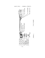
Page 7: ...TRANSCRIPTOR VESTIGIAL TONE ARM 6 ...

Page 8: ...OUNTED THE COUNTERWEIGHT IS MOUNTED ON THE MAIN HORIZONTAL ARM NEAR THE MAIN PIVOTS WHERE IT CONTROLS THE ACTION OF THE VESTIGIAL ARM BY MEANS OF A STRING AND ROLLER MECHANISM SPECIFICATIONS TRANSCRIPTOR VESTIGIAL TONE ARM Pivot to Stylus 1 3 8 Overall Length 8 3 4 Mounting Shaft Diameter 5 8 Vertical Adjustment 2 1 2 Lead Capacitance 99pf per cable Recommended Cartridge type Weight not greater th...

Page 9: ...TRANSCRIPTOR STYLUS SCALES 8 ...

Page 10: ...CCURACY OF BETTER THAN l 50th OF A GRAM THIS IS A COMPLETELY NEW CONCEPT IN THE DESIGN OF SUCH A DEVICE SUCH ACCURACY HAVING PREVIOUSLY BEEN ACHIEVED ONLY BY THOSE MANUFACTURERS USING EXPENSIVE LABORATORY BALANCE EQUIPMENT CORRECT STYLUS PRESSURE IN ACCORDANCE WITH THE RECOMMENDATIONS OF THE CARTRIDGE MANUFACTURER IS MOST IMPORTANT AND TODAY S PRESSURES ARE SO SMALL THAT THEY MAY BE CORRECTLY SET ...

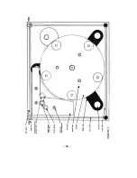
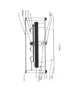
Page 11: ...osts as one unit Note that the two FRONT corner thumbnuts act as feet and are fitted with rubber discs the unit does not rest on the rear corner thumbnuts but on the center foot Make sure the unit is level when setting up Remove the top plate which covers the motor by unscrewing the three top plate retaining nuts Note that the on off switch holds a small magnet which rotates to activate a reed swi...

Page 12: ...o thumbscrews with rubber feet belong under the FRONT posts Remove the two hinge pins from the two rear posts and pass them through the holes on the side of the hinge blocks attached to the dust cover and screw into the two rear posts Use caution not to cross thread the hinge pins Note that the hinge stay mechanism is spring loaded On opening the lid the stay will automatically follow the lid and ...

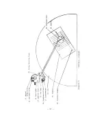
Page 13: ...y before attempting the adjustment I OVERHANG ADJUSTMENT Place a less valuable record on the turntable and place the template provided on the center post and position the stylus as shown in the picture If the arm height is low preventing the arm from swinging over the record loosen the height adjustment screw 7 on the base nut 6 and raise the arm to a point where the arm tube is approximately 1 25...

Page 14: ... be necessary to adjust the upper lower leveling screws slightly to obtain a neutral swing of the arm if a neutral swing cannot be obtained with the neutral swing screw alone 3 HEIGHT ADJUSTMENT Once again add weight to the cartridge so the stylus is in contact with the record loosen the height adjustment screw 7 and adjust the height of the arm until the cartridge platform 23 is parallel to the r...

Page 15: ...cessary step 3 and be sure the counterweight shaft is at a 45 angle with the stylus resting on the record INSTRUCTIONS FOR USE OF THE TRANSCRIPTOR SCALES When weighing or setting the scales should always be used at right angles to the arm Place weights equal to the required downward force centrally on the rubber pad on the scales platform stacking the weights where required The scales should then ...

Page 16: ...ean with a soft rag and any alcohol based cleaner Remove the lower cap on the bearing housing and remove the old oil from inside With a cotton swab clean out the inside walls of the bearing housing then re lubricate the shaft and the thrust plate with a very small amount of light weight phono oil Do not use 3 in 1 oil Reassemble the thrust plate and cap and install the ball bearing from the top of...

Page 17: ......

Page 18: ......

Page 19: ... 18 ...

Page 20: ......

Reviews: