December 2008
BAS-SVX10C-EN
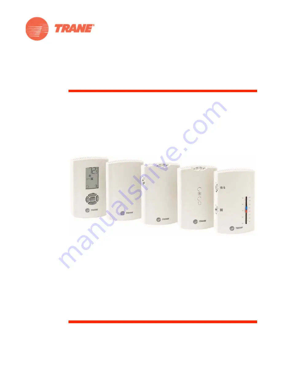
Wired Temperature Sensors
Installation, Operation, and Maintenance
Page 1: ...December 2008 BAS SVX10C EN Wired Temperature Sensors Installation Operation and Maintenance ...
Page 2: ... in the United States and other countries All trademarks referenced in this document are the trademarks of their respective owners Warnings Cautions and Notices Warnings cautions and notices are provided in appropriate places throughout this document WARNING Indicates a potentially hazardous situation which if not avoided could result in death or serious injury CAUTION Indicates a potentially haza...
Page 3: ... 17 Mounting the Back Plate 17 Installing the COMM Module optional 20 Changing the Setpoint Thumb Wheel optional 21 Wiring the Sensor 21 Replacing the Cover 22 Operation 23 Changing Temperature Settings 23 Changing System Settings 23 Changing Fan Settings 23 Selecting Temporary Occupancy Timed Override 24 Service Pin Request 25 Sensors with Occupied Unoccupied Buttons 25 Display Sensor 25 Star Dou...
Page 4: ...eration 29 Measuring Output Resistance 30 Display Sensors 30 All Models Other Than the Display Sensor 30 Cleaning the Sensor 32 Replacing the Thumb Wheel 32 Wiring Diagrams 33 Temperature sensors with fan control 34 Temperature sensors with fan and system control 37 Optional COMM module 40 Specifications and Agency Compliance 41 Specifications 41 Agency Compliance 41 Declaration of CE Conformity 4...
Page 5: ...vice tool for system communication Must be ordered separately Hot cold setpoint thumb wheel Optional accessory allows selecting a temperature setpoint by color red blue for hot cold on thumbwheel rather than by a number Must be ordered separately The display sensor p n X13790886 has an LCD display and includes an RJ11 RJ22 compatible connection for a Trane service tool for system communication The...
Page 6: ... No Yes 1 X1379085201 BAYSENS107A SEN01528 Dual Auto High Cool Off Auto Heat No No X1379083701 BAYSENS108A SEN01513 Dual Auto High Cool Off Auto Heat No Yes 4 X1379084601 BAYSENS110A SEN01522 Single Auto High Cool Off Heat No No X1379083901 BAYSENS106A SEN01515 Single Low High Cool Off Heat Fan No No X1379085001 NA SEN01526 Temperature sensor with LCD display 1 2 Single No No Yes No X1379088601 NA...
Page 7: ...on details The dimensions are the same for all models 2 9 in 73 5 cm 1 08 in 27 5 mm 4 68 in 118 9 mm 1 45 in 36 8 mm 0 63 in 15 9 mm 0 31 in 8 mm 0 12 in 3 mm TYP R 07 in R1 9 mm 3 39 in 86 mm 2 48 in 63 mm 2 62 in 66 5 mm TYP 0 24 in 6 mm Note There is no center mounting hole on the display sensor ...
Page 8: ...s to reduce accidental damage or tampering Height Requirements The recommended maximum mounting height is 54 inches from the bottom of the back plate to the floor If a parallel approach by a person in a wheelchair is required reduce the maximum height to 48 inches Note Consult section 4 27 3 of the 2002 ADA Americans with Disability Act guideline and local building codes for further details regard...
Page 9: ...ified by color Mounting the Back Plate WARNING Hazardous voltage Disconnect all electric power including remote disconnects before servicing Follow proper lockout tagout procedures to ensure the power cannot be inadvertently energized Failure to disconnect power before servicing could result in death or serious injury NOTICE Equipment damage Applying excessive voltage to the sensor will permanentl...
Page 10: ...ion in the terminal block see the table in Figure 1 Tighten the terminal screw Note The wire connections can be made while the terminal block is either on the circuit board or removed from it 3 Perform a pull test to ensure that the wires are properly connected 4 If the terminal block was removed from the circuit board attach it to the pins inside the sensor cover Figure 1 5 Push the excess wire i...
Page 11: ...o limit tenant access to certain features This can be done through configuration Or if a sensor is configured to match all controllable features of the associated equipment the locking feature can be used to restrict the tenant from making changes Configuration Procedure To configure settings on the sensor follow this procedure in the order presented 1 Press the configuration button for 3 seconds ...
Page 12: ... next menu as illustrated Center button Setting Configuration options Temperature Choose Fahrenheit or Celsius Choose the degree resolution whole degrees half degrees or tenths of degrees Setpoint Deadband available for dual setpoint system only Note Deadband refers to the minimum difference between the heating and cooling setpoints System a Single setpoint dual setpoint no i single i heat cool se...
Page 13: ...an options are available for all systems Occupancy timed override Setting Configuration options emergency heat heat cool off heat cool auto off emergency heat heat cool auto off no system options enabled auto off low med high auto off low high auto off off high on off low high off low med high no fan options enabled auto high on ...
Page 14: ...g mode If an error code exists it appears at the bottom of the display between the occupancy symbols as shown below See Error codes p 28 for error code definitions The example shows a display that has been configured for Dual setpoint Temperature units Fahrenheit Temperature resolution to tenths of a degree System settings Emergency Heat Heat Cool Off Fan settings Auto or On Occupied unoccupied op...
Page 15: ...he illustration Locking or Unlocking Settings You can lock or unlock the setpoint system or fan setting to prevent changes To lock or unlock a setting 1 Verify that the sensor is in operating mode and at the home screen 2 Choose a setting to lock or unlock Select the setpoint by pressing the up or down arrow Select the system menu by pressing the center button Use the left or right arrow to choose...
Page 16: ...o access a feature that is locked the locked symbol appears on the display If you press a keypad button to try change a locked setting the locked symbol flashes Replacing the Cover To replace the cover 1 Hook the cover over the top of the back plate Apply light pressure to the bottom of the cover until it snaps in place 2 Secure the cover by installing the security screw into the bottom of the cov...
Page 17: ...that there is continuity between the location and the controller and that the wires are accurately labeled or identified by color Mounting the Back Plate WARNING Hazardous voltage Disconnect all electric power including remote disconnects before servicing Follow proper lockout tagout procedures to ensure the power cannot be inadvertently energized Failure to disconnect power before servicing could...
Page 18: ...ld the back plate against the mounting surface and mark the screw locations 6 Secure the back plate to the mounting surface using the included hardware 7 Feed the wires through the opening in the circuit board 8 Replace the circuit board by sliding the right side of the board under the two catches on the right side of the back plate while aligning slot on board with tab on back plate Press firmly ...
Page 19: ...BAS SVX10C EN 19 Installation All Models Other Than the Display Sensor Circuit board fits under catches Slot on circuit board aligns with tab on back plate ...
Page 20: ... a local RJ22 connection to a Trane service tool for maintenance use It must be ordered separately Install the COMM module before wiring the sensor 1 Slide the two cutouts on the right side of the COMM module into the two keys on the back plate 2 Press firmly on the left side of the COMM module board until it snaps into place Thumb catch COMM module Catches ...
Page 21: ...ecurely onto the back plate 3 Rotate the replacement thumb wheel until the stop is opposite the flat portion of the potentiometer Push down on the thumb wheel until the ribs touch the potentiometer After it is inserted the thumb wheel should turn freely Wiring the Sensor WARNING Hazardous voltage Disconnect all electric power including remote disconnects before servicing Follow proper lockout tago...
Page 22: ... Sensor Replacing the Cover To replace the cover 1 Hook the cover over the top of the back plate Apply light pressure to the bottom of the cover until it snaps in place 2 Secure the cover by installing the security screw into the bottom of the cover Security screw ...
Page 23: ...Changing Heating and Cooling Temperature Settings dual setpoint systems only p 27 Changing System Settings To change system settings For sensors with system thumb wheels located on the upper left side rotate the thumb wheel to the desired setting For the display sensor see Changing System Settings p 28 Notes Not all sensor models have all system setting options The effect of setting changes are de...
Page 24: ...ith Occupied Unoccupied buttons To select temporary occupancy press the Occupied button Figure 2 for 0 2 6 seconds The following occurs Space temperature output is driven to 10 Ω nominal The output generates for 4 seconds To cancel temporary occupancy press the Unoccupied button Figure 2 for 0 2 6 seconds The following occurs Space temperature output is driven to 1330 Ω nominal The output generate...
Page 25: ... support occupancy and must be in operating mode see Configuring the Display Sensor p 11 To initiate a service pin request 1 With the sensor in operating mode navigate to the occupancy menu 2 Press the right arrow on the keypad Figure 3 The occupied symbol remains on the screen the unoccupied symbol leaves the screen 3 Press and hold the center button for 10 seconds The following occurs The wrench...
Page 26: ... is communicated Double star A value of 44 6ºF 7ºC is communicated Display Sensor The display sensor supports the star and double star functions if the sensor is configured for single setpoint operation Press the up or down arrow on the keypad to display the star or double star respectively on the sensor display If the setpoint is increased one increment above 89 6ºF 32ºC the star appears A value ...
Page 27: ...e home screen When you select a setpoint this symbol appears Some systems allow you to select both heating and cooling room temperature settings If your system has this option this symbol appears when you adjust the temperature setting 1 Press or to select the heating cooling setting 2 If in cooling mode press to change to heating mode If in heating mode press to change to cooling mode 3 Press or ...
Page 28: ...ppear or Waiting 5 seconds Indicates that the fan setting is On The number of arrows indicates fan speed 3 high 2 medium 1 low The example shown indicates a fan on high speed Not all systems offer all three speeds Indicates fan is Off Select to request occupancy If you need heating or cooling after normal business hours you can request temporary occupancy by pressing and holding it for 2 seconds T...
Page 29: ...he unit controller Cool LED green The green cool LED indicates that the system is in cooling mode Stays on solid during normal cooling operation Blinks to indicate a cooling system failure Heat LED green The green heat LED indicates that the system is in heating mode Stays on solid during normal heating operation Blinks to indicate a heating system failure System LED green The green system LED ind...
Page 30: ...asure between the SYS FAN MODE terminal 4 and the SIGNAL COMMON terminal 2 Compare resistance measurements to those in Table 2 Notice Potential Equipment Damage Because the output circuits are not electrically powered resistance can be measured without risk of damage to the volt ohm meter However damage to the volt ohm meter could potentially result if terminal 11 24 VAC VDC is inadvertently conta...
Page 31: ...nts of scale 55ºF 12 8ºC and 85ºF 29 4ºC Dual setpoint systems Cooling setpoint varies 10 Ω at 70ºF 21 1ºC varies at 110 Ω at endpoints of scale Heating setpoint varies 20 Ω at 70ºF 21 1ºC varies at 120 Ω at endpoints of scale Table 2 Resistance measurements for fan and system modes Fan mode System mode Nominal output resistance Auto or invalid Emergency heat 35 000 Ω Auto or invalid Heat 19 480 Ω...
Page 32: ... cloth and gently wiping the face including the buttons and LCD display Use of a pre moistened towelette designed for lens or screen cleaning is also acceptable Avoid inadvertent pressing buttons on sensors that have them or the keypad on the display sensor as this may result in an unwanted timed override or settings change Replacing the Thumb Wheel If you need to replace a setpoint thumb wheel se...
Page 33: ...3270 3435 B Zone temperature Signal common Setpoint 1 2 3 Calibration potentiometer Pot 2 see Note NOTE POT 1 and POT2 are factory calibrated Field adjustment voids warranty Zone temperature Signal common 1 2 RT1 thermistor 10 k at 25 C Ω Dwg source 3270 3436 Zone temperature Signal common 1 2 RT1 thermistor 10 k at 25 C Ω Setpoint 3 Setpoint Pot 1 1 k potentiometer Ω Calibration potentiometer Pot...
Page 34: ... 5 kW Timed override On SW3 Thermistor 10 k at 25 C W 1 2 4 Calibration Pot 1 see Note 1 RT1 Note 1 Pot 1 is factory calibrated Field adjustment voids warranty 3 R1 4 87 kW R2 2 32 kW Auto Off R11 zero W Signal common Cool setpoint CSP Zone temperature Mode Fan switch TB1 R10 zero W Temperature setpoint Pot 5 1 kW Fan SW1 Dwg source X39641092 01 X1379084501 Temperature sensors with fan control X13...
Page 35: ...nal common Cool setpoint CSP Zone temperature Mode System switch TB1 Dwg source X39641098 01 X1379085101 Timed override Cancel SW4 R9 1 5 kW Timed override On SW3 Thermistor 10 k at 25 C W 1 2 4 Calibration Pot 1 see Note 1 RT1 Note 1 Pot 1 is factory calibrated Field adjustment voids warranty 3 R1 4 87 kW R2 2 32 kW R3 10 7 kW Low Auto Off R5 16 2 kW High R11 zero W R10 zero W Signal common Cool ...
Page 36: ...1 R10 zero W Temperature setpoint Pot 5 1 kW Fan SW1 Dwg source X39641088 01 X1379084101 Timed override Cancel SW4 R9 1 5 kW Timed override On SW3 Thermistor 10 k at 25 C W 1 2 4 Calibration Pot 1 see Note 1 RT1 Note 1 Pot 1 is factory calibrated Field adjustment voids warranty 3 R1 4 87 kW R2 2 32 kW R3 10 7 kW R4 13 3 kW Med Low Auto Off R5 16 2 kW High R11 zero W Signal common Cool setpoint CSP...
Page 37: ...t R9 zero Ω Signal common Cool setpoint CSP Heat Setpoint HSP Zone temperature TB1 Mode Sys Fan switch System SW1 Fan SW2 Cool setpoint Pot 4 1 kΩ Dwg source X39641094 01 RT1 thermistor 10 k at 25 C W Temperature setpoint Pot 5 1 kW 1 2 4 Calibration Pot 1 see Note 1 Note 1 Pot 1 is factory calibrated Field adjustment voids warranty 3 R6 8 45 kW Auto On R1 4 87 kW R2 2 32 kW R3 19 6 kW Heat Off Co...
Page 38: ...t Pot 3 1 kW System SW1 Fan SW2 Dwg source X39641084 01 RT1 thermistor 10 k at 25 C W 1 2 4 Calibration Pot 1 see Note 1 R7 3 92 kW Note 1 Pot 1 and Pot 2 are factory calibrated Field adjustment voids warranty 3 5 R6 8 45 kW Auto On R8 3 92 kW Calibration Pot 2 see Note 1 R1 4 87 kW R2 2 32 kW R3 7 68 kW R4 19 6 kW Heat Auto Off Cool CR2 Green CR4 Green CR3 Green CR1 Red 6 7 9 8 10 LED Service LED...
Page 39: ...emperature TB1 Auto On Temperature setpoint Pot 5 1 kW System SW1 Fan SW2 Dwg source X39641086 01 2 4 Calibration Pot 1 see Note 1 Note 1 Pot 1 is factory calibrated Field adjustment voids warranty 3 R6 8 45 kW Auto On R1 4 87 kW R2 2 32 kW R3 7 68 kW Heat Off Cool R4 19 6 kW Fan RT1 thermistor 10 k at 25 C W 1 R11 zero W Signal common Cool setpoint CSP Zone temperature TB1 Mode Sys Fan switch Tem...
Page 40: ...40 BAS SVX10C EN Wiring Diagrams 2 1 COMM Module J1 2 3 Optional COMM module X1365146702 ...
Page 41: ... C Setpoint markings Setpoint thumb wheel 50 F to 85 F in 5 F increments and 10 C to 29 C in 3 C increments and Dual setpoint slider 50 to 85ºF stamped every 5ºF 10 to 29ºC stamped every 3ºC Housing material Polycarbonate ABS blend UV protected UL 94 5VA flammability rating suitable for application in a plenum Mounting Fits a standard 2 in by 4 in junction box vertical mount only Mounting holes ar...
Page 42: ...d EN55011 2006 Class B limit Harmonic EN61000 3 2 Class A limit Flicker EN61000 3 3 1995 A1 2001 A2 2006 Electromagnetic Immunity for Industrial by Council Directive 89 336 EEC EN61326 1 2006 EN61000 2 2006 4 0 kV by contact 8 0 kV by air EN61000 4 3 2006 10 0 V m EN61000 4 4 2006 1 0 kV signal lines 2 0 kV ac power lines EN61000 4 5 2006 1 0 kV signal lines 2 0 kV ac power lines EN61000 4 6 2006 ...
Page 43: ...BAS SVX10C EN 43 Specifications and Agency Compliance ...
Page 44: ...BAS SVX10B EN March 2008 Trane has a policy of continuous product and product data improvement and reserves the right to change design and specifications without notice www trane com For more information contact your local Trane office or e mail us at comfort trane com ...