background image

68

TK 55676-19-IM-EN

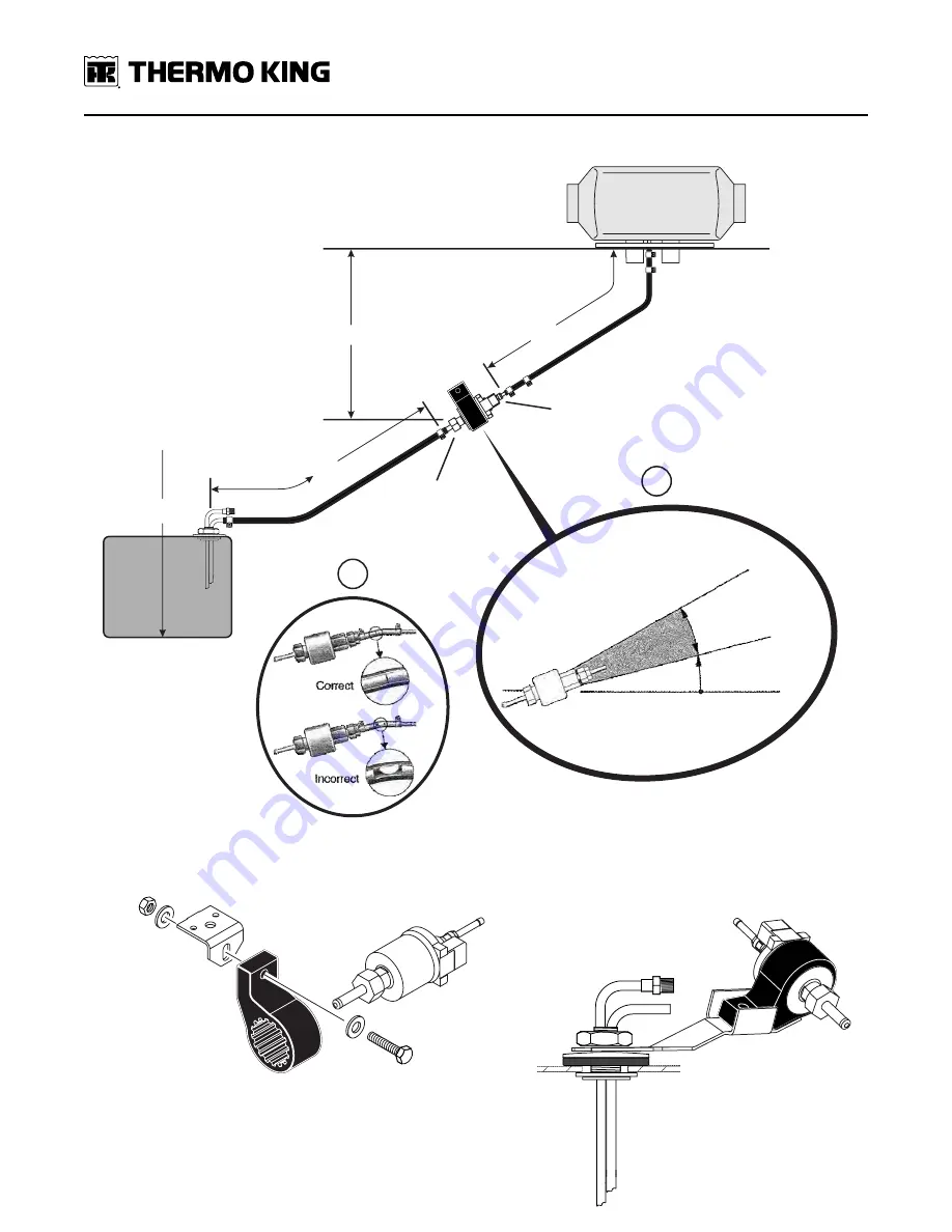
Figure 38.

Heater Fuel Pump and Fuel Line Installation Shown

B

Max. 2’6”

Fuel

Tank

Max. 2’

Max. 6’6”

Max. 20’

Inlet

Outlet

35°

15°

Preferable

Not Permissable

FUEL PUMP

ANGLE

A

L-BRACKET

FUEL TANK BRACKET

ABA316-1

H

He

ea

atte

err F

Fu

ue

ell P

Pu

um

mp

p a

an

nd

d F

Fu

ue

ell L

Liin

ne

e IIn

nsstta

alllla

attiio

on

n

Summary of Contents for Thermo King TriPac EVOLUTION

Page 1: ...Revision A November 2020 T TK K 5 55 56 67 76 6 1 19 9 I IM M E EN N TriPac EVOLUTION Auxiliary Heating and Cooling Temperature Management System Installation Manual...

Page 2: ...erienced mechanic can safely lift 75 lbs 34 kilos are EPA Section 609 certified and trained in the repair and maintenance of diesel powered refrigeration systems have a basic understanding of electric...

Page 3: ...ectrical Wiring and HMI Controller Installation 13 T Tr ri iP Pa ac c E Ev vo ol lu ut ti io on n C Co om mp po on ne en nt t D Di im me en ns si io on ns s 1 14 4 APU 14 Condenser 16 Evaporator 17 Co...

Page 4: ...e ea at te er r D Du uc ct t I In ns st ta al ll la at ti io on n 4 42 2 Duct Locations 42 Installation Procedures 42 A A C C D Du uc ct t I In ns st ta al ll la at ti io on n 4 44 4 A C Vent Location...

Page 5: ...Connections 70 Installation Procedures 70 Alternative Installation APU Coolant Hoses Attached Directly To Fittings On Tractor s Engine 72 Coolant Hose Routing and Connections 72 Installation Procedure...

Page 6: ...6 TK 55676 19 IM EN Verifying Engine Operation 89 Unit Setup Procedures 90 Service Run In Test 93 System Check List 95 T Ta ab bl le e o of f C Co on nt te en nt ts s...

Page 7: ...r re e w wh hi ic ch h m mi ig gh ht t c ca au us se e a an n e ex xp pl lo os si io on n r re es su ul lt ti in ng g i in n d de ea at th h o or r s se er ri io ou us s i in nj ju ur ry y D DA AN NG...

Page 8: ...or rr re ec ct t l le en ng gt th h f fo or r t th he ei ir r a ap pp pl li ic ca at ti io on ns s a an nd d t to or rq qu ue ed d t to o s sp pe ec ci if fi ic ca at ti io on n I In nc co or rr re e...

Page 9: ...th he e o oi il l R Ru ub bb be er r g gl lo ov ve es s a ar re e r re ec co om mm me en nd de ed d First Aid R RE EF FR RI IG GE ER RA AN NT T E Ey ye es s For contact with liquid immediately flush e...

Page 10: ...present Do not store or transport combustibles road flares starting fluids fuel containers oil cans spray cans gas cartridges fire extinguishers cleaning rags clothing paper etc in the same compartmen...

Page 11: ...is designed to be mounted only to the existing frame rails N NO O O OT TH HE ER R M MO OU UN NT TI IN NG G I IS S A AC CC CE EP PT TA AB BL LE E Determine the best location for installing the APU on t...

Page 12: ...and resin Outside air intake and exhaust hoses must be installed correctly for the heater to operate safely Exhaust hose should be mounted slightly downwards to help drain off condensation Install ex...

Page 13: ...afing against sharp metal objects rotating components or hot objects All coolant pipe fittings installed should be of proper material type i e brass to brass or copper to copper All coolant fittings s...

Page 14: ...14 TK 55676 19 IM EN TriPac Evolution Component Dimensions APU Figure 1 TriPac Evolution APU Dimensions side and front...

Page 15: ...TK 55676 19 IM EN 15 Figure 2 TriPac Evolution APU Dimensions side and rear T Tr ri iP Pa ac c E Ev vo ol lu ut ti io on n C Co om mp po on ne en nt t D Di im me en ns si io on ns s...

Page 16: ...16 TK 55676 19 IM EN Condenser Figure 3 TriPac Evolution Condenser Dimensions T Tr ri iP Pa ac c E Ev vo ol lu ut ti io on n C Co om mp po on ne en nt t D Di im me en ns si io on ns s...

Page 17: ...TK 55676 19 IM EN 17 Evaporator Figure 4 TriPac Evolution Evaporator Dimensions T Tr ri iP Pa ac c E Ev vo ol lu ut ti io on n C Co om mp po on ne en nt t D Di im me en ns si io on ns s...

Page 18: ...18 TK 55676 19 IM EN Control Box Figure 5 TriPac Evolution Control Box Dimensions T Tr ri iP Pa ac c E Ev vo ol lu ut ti io on n C Co om mp po on ne en nt t D Di im me en ns si io on ns s...

Page 19: ...Dimensions RCS1660 BACK VIEW FRONT VIEW SIDE VIEW 203 mm 8 00 in 29 mm 1 10 in 139 7 mm 5 50 in 50 8 mm 2 00 in 46 6 mm 1 80 in 76 2 mm 3 00 in 98 55 mm 3 88 in T Tr ri iP Pa ac c E Ev vo ol lu ut ti...

Page 20: ...20 TK 55676 19 IM EN Standard Heater Figure 7 Standard Heater Dimensions T Tr ri iP Pa ac c E Ev vo ol lu ut ti io on n C Co om mp po on ne en nt t D Di im me en ns si io on ns s...

Page 21: ...TK 55676 19 IM EN 21 High Output Heater Figure 8 High Output Heater Dimensions T Tr ri iP Pa ac c E Ev vo ol lu ut ti io on n C Co om mp po on ne en nt t D Di im me en ns si io on ns s...

Page 22: ...9 Level 10 Tape Measure 11 Utility Knife 12 Caulk Gun 13 Tubing Cutter for cutting fuel pickup tubes 14 Strobe Light Tachometer 204 436 15 Digital Meter 204 615 16 Leak Detector 204 756 17 Hose Fittin...

Page 23: ...he Thermo King TriPac Installation Standards Guide TK 56498 before beginning the installation Adhering to the installation standards will help assure the components are installed correctly and the sys...

Page 24: ...A C Condenser 9 Heater Intake Tube 3 A C Receiver Drier 10 Heater Fuel Pump 4 A C Evaporator 11 Diesel Fuel Pickup Tube 5 Control Box 12 Main Power Fuse connects to truck s batteries 6 HMI Controller...

Page 25: ...U Auxiliary Power Unit 8 Heater Exhaust Tube 2 A C Condenser 9 Heater Intake Tube 3 A C Receiver Drier 10 Heater Fuel Pump 4 A C Evaporator 11 Diesel Fuel Pickup Tube 5 Control Box 12 Main Power Fuse...

Page 26: ...ight to tractor frame b Adjust height of the APU so top and bottom mounting claws and bolts are positioned flat on frame Review Detail A c Lightly tighten mounting hardware only enough to remove exces...

Page 27: ...676 19 IM EN 27 Figure 12 Standard Installation Method with Mounting Claws Shown Detail C INCORRECT Detail B INCORRECT Detail A Correct 5 6 ABA705 2 2 8 1 3 4 A AP PU U I In ns st ta al ll la at ti io...

Page 28: ...ensions are available for this purpose Contact your nearest Thermo King Dealer Standard Short Exhaust Tailpipe A short exhaust tailpipe is provided standard with each APU 1 Install the short exhaust t...

Page 29: ...enser housing and coil assembly can be also installed with the hose fittings facing towards the roadside D DE ET TA AI IL L A A if needed When doing so the actual condenser coil must be removed from t...

Page 30: ...30 TK 55676 19 IM EN Figure 14 Typical Condenser Installation Shown A A C C C Co on nd de en ns se er r I In ns st ta al ll la at ti io on n...

Page 31: ...the exterior of the tractor to install the receiver drier Typical Mounting Locations a Side by side Mount D DE ET TA AI IL L A A b Mid height Mount D DE ET TA AI IL L B B c High Mount D DE ET TA AI IL...

Page 32: ...s up inside the sleeper through existing access hole N No ot te e Sensor harness should be secured with cable ties to the other harnesses already installed and routed into sleeper 5 Route the sensor h...

Page 33: ...upport members Special Tools Required Drill Motor 1 4 Drill Bit 7 8 Step Reamer 3 dia Hole Saw Reciprocating Saw Caulk Gun and RTV Silicone Sealant Sealing Putty 203 391 Fiberglass Cloth and Resin Kit...

Page 34: ...K 55676 19 IM EN Figure 17 Preferred Location Flush with Bulkhead Shown TEMPLATE 1 2 4 6 7 5 3 ARD332 3 14 x 7 minimum bulkhead A A C C E Ev va ap po or ra at to or r I In ns st ta al ll la at ti io o...

Page 35: ...s support members Special Tools Required Drill Motor 1 4 Drill Bit 7 8 Step Reamer 3 dia Hole Saw Reciprocating Saw Caulk Gun and RTV Silicone Sealant Sealing Putty 203 391 Fiberglass Cloth and Resin...

Page 36: ...M EN Figure 18 Alternative Location Centered Under Bunk Shown 4 2 6 ARD333 2 1 Return Air Vent 5 TEMPLATE 3 14 x 7 minimum bulkhead opening A A C C E Ev va ap po or ra at to or r I In ns st ta al ll l...

Page 37: ...must be located outside the tractor Install exhaust hose so it will maintain a minimum distance of 2 00 inches 50 8 mm from any heat sensitive or flammable material Heater must be mounted on flat hori...

Page 38: ...center and tighten securely 6 Insert the plastic air intake tube through the beveled opening of the small plastic mounting plate Install the plastic plate and tube onto studs located under the INLET e...

Page 39: ...TK 55676 19 IM EN 39 Figure 20 Heater Subassembly Shown D D2 2 D D4 4 H He ea at te er r I In ns st ta al ll la at ti io on n...

Page 40: ...ds to help drain off condensation Install the protective cap onto the end of the exhaust hose Route the exhaust hose to an open area to the rear or side of the tractor so fumes cannot build up and ent...

Page 41: ...TK 55676 19 IM EN 41 Figure 21 Correct Exhaust and Combustion Air Intake Routing Shown D D2 2 D D4 4 H He ea at te er r I In ns st ta al ll la at ti io on n...

Page 42: ...y opposite the discharge outlet vent Discharge Outlet should be located at floor level to provide maximum heating comfort in the sleeper It is typically installed at the base of the bunk on one end He...

Page 43: ...TK 55676 19 IM EN 43 Figure 22 D2 D4 Heater Duct Installation Shown D D2 2 D D4 4 H He ea at te er r D Du uc ct t I In ns st ta al ll la at ti io on n...

Page 44: ...charge hose s directly into the truck s OEM HVAC duct s The damper will prevent the TriPac s air from back flowing into the OEM HVAC housing Failure to install this kit may result in poor system perfo...

Page 45: ...TK 55676 19 IM EN 45 Figure 23 Typical A C Duct Installation Shown Figure 24 Example of a Back Flow Damper Shown A A C C D Du uc ct t I In ns st ta al ll la at ti io on n...

Page 46: ...route the 8 hose into the APU through the upper access hole and the 10 hose through the lower access hole making sure you route them through the pre installed bandwraps attached to the support bracket...

Page 47: ...e length attach a 8 8 f fi it tt ti in ng g and connect to the 8 discharge fitting located near the top of the condenser coil E Ev va ap po or ra at to or r t to o R Re ec ce ei iv ve er r D Dr ri ie...

Page 48: ...R CONDENSER RECEIVER DRIER 10 8 6 6 8 LIQUID COMPRESSOR OUTLET INLET SUCTIO N IMPORTANT The suction and discharge hoses must be secured to the refrigerant hose support bracket exactly as shown in the...

Page 49: ...ystem reaches 500 microns 5 Once the system reaches 500 microns continue evacuation for one additional hour N No ot te e To save installation time while the system is being evacuated continue on to th...

Page 50: ...55676 19 IM EN Figure 27 Gauge Manifold and Vacuum Pump Shown Connected to APU A A C C S Sy ys st te em m E Ev va ac cu ua at ti io on n a an nd d L Le ea ak k C Ch he ec ck k P Pr ro oc ce ed du ur r...

Page 51: ...ns for straightness before attempting to mate connectors If any resistance is felt when mating the connector recheck the male pin alignment 1 Position the control box inside the truck and remove the c...

Page 52: ...52 TK 55676 19 IM EN Figure 28 Main Harness Connections to Control Box Shown C Co on nt tr ro ol l B Bo ox x a an nd d M Ma ai in n H Ha ar rn ne es ss s I In ns st ta al ll la at ti io on n...

Page 53: ...n harness connector to the HMI J J3 34 4 connector on the main controller board inside the control box 2 From the control box route the harness behind the interior walls if applicable to the location...

Page 54: ...ns Shown RCS1676 4 3 2 1 N No ot te e Attach the supplied Operator Manual nameplate in a location inside the tractor chosen by the driver Figure 30 Online Access to Operator Manual Nameplate Shown RCS...

Page 55: ...t to o u un nl lo oc ck k from the connector body b connect the two 16 pin connectors together c push locking tab back in t to o l lo oc ck k the connector body 2 Route the heater control harness con...

Page 56: ...to the 8 individual wires 4 Measure approximately 102 to 152 mm 4 00 to 6 00 in from the connector and splice the following two wires together using butt splice connectors a Brown White wire from heat...

Page 57: ...Connect 4 pin connector to AC EVAP connector J1 5 Route harnesses 7CF 7CF RTN and 7CL 7CLA out of the sleeper through the 3 access hole towards the condenser coil 6 Attach connector 7CL 7CLA to the r...

Page 58: ...58 TK 55676 19 IM EN Figure 33 A C Harness Connections Shown A A C C W Wi ir ri in ng g I In ns st ta al ll la at ti io on n...

Page 59: ...Typically the standby switch is installed in the dashboard in a location that is easily accessible for the driver 1 Remove dash panel if required Mark and drill 1 2 hole 2 Install the standby switch...

Page 60: ...19 IM EN Figure 34 Standby Harness with Switch Connections Shown S St ta an nd db by y T Tr ru uc ck k I In nt te eg gr ra at ti io on n H Ha ar rn ne es ss s w wi it th h S Sw wi it tc ch h O Op pt...

Page 61: ...and re check for voltage at the same wire connection tested earlier If voltage is present this is where the IGN wire will be connected 1 Connect I IG GN N wire with in line fuse to WIRE VEHICLE CONNE...

Page 62: ...EN Figure 35 Standby Harness without Switch Connections Shown S St ta an nd db by y T Tr ru uc ck k I In nt te eg gr ra at ti io on n H Ha ar rn ne es ss s w wi it th ho ou ut t S Sw wi it tc ch h O...

Page 63: ...Tools Required Tape Measure Tubing Cutter Torque Wrench IMPORTANT INSTALLATION TIPS Identify and mark APU FUEL SUPPLY pickup tube for reference later Remove protective caps from ends of pickup tubes p...

Page 64: ...64 TK 55676 19 IM EN Figure 36 Optional Adapter Plate Installation Shown F Fu ue el l P Pi ic ck ku up p T Tu ub be e I In ns st ta al ll la at ti io on n...

Page 65: ...rg ge e t th he e d di ie es se el l v va ap po or rs s f fr ro om m t th he e t ta an nk k p pr ri io or r t to o d dr ri il ll li in ng g i in nt to o o or r a ar ro ou un nd d t th he e f fu ue el...

Page 66: ...o facilitate fuel line connections and tighten nut to 16 to 18 ft lb 21 to 24 N m 7 Install supplied warning nameplate onto fuel tank in a visible area near fuel cap Figure 37 Alternative Installation...

Page 67: ...e nut to 16 to 18 ft lb 21 to 24 N m N No ot te e The bracket goes under the nut not under the washer or rubber gasket 2 Install the fuel pump into the supplied rubber mounting clamp and attach the ru...

Page 68: ...tion Shown B Max 2 6 Fuel Tank Max 2 Max 6 6 Max 20 Inlet Outlet 35 15 Preferable Not Permissable FUEL PUMP ANGLE A L BRACKET FUEL TANK BRACKET ABA316 1 H He ea at te er r F Fu ue el l P Pu um mp p a...

Page 69: ...and marked earlier 1 Route APU fuel supply line to S SU UP PP PL LY Y connection of fuel pickup tube cut to proper length and attach with compression fittings 2 Route APU fuel return line to R RE ET T...

Page 70: ...tor s engine block through an I IN NL LE ET T fitting typically located near the water pump Hot coolant circulates through the tractor s engine block and exits an O OU UT TL LE ET T fitting typically...

Page 71: ...lied coolant nameplate in a visible area near the tractor s coolant fill cap Figure 40 APU Coolant Hoses Tee d Directly Into Tractor s Heater Hoses Shown HEATER HOSE ABA715 1 OUTLET OUTLET INLET TRACT...

Page 72: ...pump Hot coolant circulates through the tractor s engine block and exits an O OU UT TL LE ET T fitting typically used for the heater Warm coolant then returns to the TriPac APU and enters the I IN NL...

Page 73: ...upplied coolant nameplate in a visible area near the tractor s coolant fill cap Figure 41 APU Coolant Hoses Attached Directly To Fittings On Tractor s Engine Shown TRACTOR ENGINE OUTLET OUTLET INLET T...

Page 74: ...po os si it ti io on n B BE EF FO OR RE E c co on nn ne ec ct ti in ng g w wi ir re es s t to o b ba at tt te er ry y 1 Locate Arctic Option harness W WT T2 2 W WT T2 2 R RT TN N band wrapped inside u...

Page 75: ...TK 55676 19 IM EN 75 Figure 42 Arctic Switch Installation Shown A Ar rc ct ti ic c S Sw wi it tc ch h O Op pt ti io on n...

Page 76: ...tt te er ry y 1 Route the heater fuel pump harness down to the fuel pump and cut the wires to the correct length a Strip wire ends slide on rubber sealing boots attach pin terminals securely with crim...

Page 77: ...nd of in line fuse Attach terminal ring firmly to wire h Position heat shrink tubing to cover exposed wires on terminal ring and use a heat gun to shrink tubing in place This wire will be attached in...

Page 78: ...55676 19 IM EN b Tighten the nuts to 120 in lb 13 5 N m and close the fuse holder cover securely F Fu us se e H Ho ol ld de er r a an nd d A AP PU U B Ba at tt te er ry y C Co on nn ne ec ct ti io on...

Page 79: ...ve e B Ba at tt te er ry y C Co on nn ne ec ct ti io on n B BL LA AC CK K to N Ne eg ga at ti iv ve e B Ba at tt te er ry y C Co on nn ne ec ct ti io on n 3 Turn the priming harness switch to the O ON...

Page 80: ...to read out display and delete faults stored in the heater s electronic control box It may also be used to start and run the heater The test duration is limited to a maximum of 120 minutes The electro...

Page 81: ...e It will be connected after the Heater Start Up Procedures have been completed 2 Connect the adapter harness to the Diagnostic Tool 3 Connect the 8 pin diagnostic connector to the mating connector lo...

Page 82: ...ible Displays If no errors faults exist go to Heater Start up If errors faults exist go to Clearing Faults Communication error exist Go to Unable to Perform the Diagnosis Heater Start Up The heater wi...

Page 83: ...aults in memory Display e g F1 20 Record all fault codes Refer to the diagnostic manual for an explanation of fault code diagnosis Display current fault in fault memory again Simultaneously press the...

Page 84: ...t th he e D Di ia ag gn no os si is s A Ag ga ai in n Press activation button display is activated U Un na ab bl le e t to o P Pe er rf fo or rm m t th he e D Di ia ag gn no os si is s Automatic detec...

Page 85: ...n nt t Before starting the APU engine oil and coolant levels must be checked to prevent damage to the engine and the A C system must have a partial charge of refrigerant added to prevent damage to the...

Page 86: ...Test before performing the Run in Procedures 9 Start the TriPac engine 10 The remaining air in the system will be forced to the tractor radiator and the TriPac APU should now be bled of all air Bleedi...

Page 87: ...the engine for 2 minutes to allow the thermostat to heat soak and open completely to purge air out of block head and water pump 9 After 2 minutes re start the engine 10 Remove the expansion tank cap a...

Page 88: ...te e The fuel pump only runs when the engine is turning over If the engine cranks for 30 seconds and fails to start a start fault shutdown will be generated This alarm code will have to be cleared bef...

Page 89: ...low engine to reach operating temperature 4 Add compressor and alternator load to the engine adjust engine speed to 2350 RPMs Figure 49 Engine RPM Adjustment Tag Shown RCS1671 With the engine running...

Page 90: ...r T TK K M Mo on ni it to or r 1 Turn the unit on by pressing the M Mo od de e button on the HMI the knob on the left for 2 seconds 2 With control box cover removed Check the green heartbeat LED on t...

Page 91: ...ble in TK Monitor A different screen may be select by mouse clicking any one of them RCS1667 9 Select the U Un ni it t S Se et tu up p Screen This screen allows the technician to configure the unit ba...

Page 92: ...r Record the 10 digit TriPac EVOLUTION unit serial number from the unit identification plate 13 Enter U Un ni it t I ID D Enter a unique unit ID number The truck number is commonly used Can be any co...

Page 93: ...VOLUTION unit to the customer it must complete a 10 hour run in with the engine under load The Run In Test in the Service Test screen will cause both the air conditioning system using a low temperatur...

Page 94: ...st will stop automatically at the end of 10 hours 8 A shutdown alarm will display on the HMI 9 Reconnect computer and start TK Monitor 10 Go to the Alarm screen 11 Clear the code 54 Test Mode Timeout...

Page 95: ...es Routed Safely and Secured Heater System Operates Correctly All Fuel Lines are Routed Safely and Secured All Fuel Line Connections are Tight and Leak Free All Guards Covers and Grilles Installed Sec...

Page 96: ...ruck bodies buses air shipboard containers and railway cars since 1938 For more information visit www thermoking com or www tranetechnologies com Thermo King has a policy of continuous product and pro...

Reviews: