background image

February 2021

ARTC-SVX005A-EN

SAFETY WARNING

Only qualified personnel should install and service the equipment. The installation, starting up, and servicing of 
heating, ventilating, and air-conditioning equipment can be hazardous and requires specific knowledge and training. 
Improperly installed, adjusted or altered equipment by an unqualified person could result in death or serious injury. 
When working on the equipment, observe all precautions in the literature and on the tags, stickers, and labels that are 
attached to the equipment.

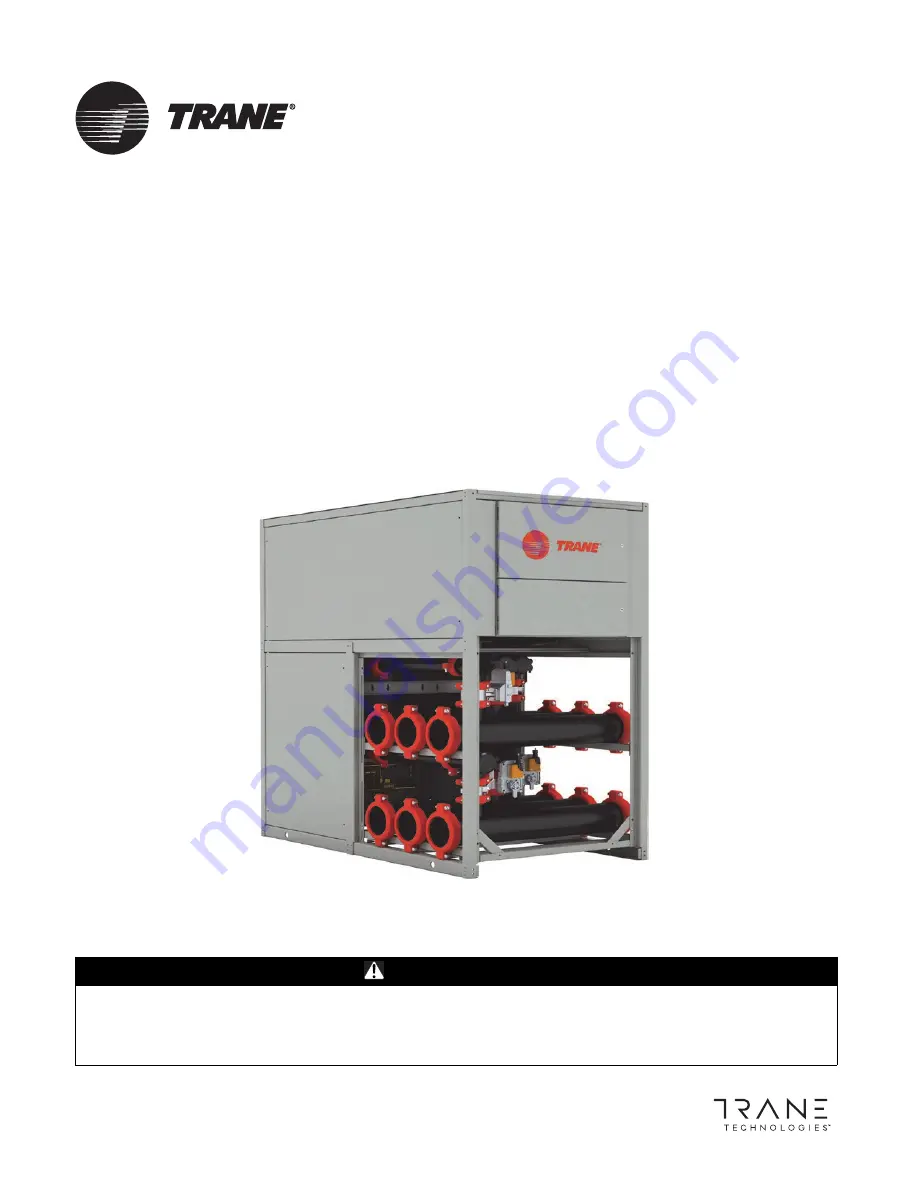
PolyTherm™ Simultaneous
Chiller/Heater

Installation, Operation, and Maintenance

Summary of Contents for PolyTherm ARTC-SVX005A-EN

Page 1: ...ment can be hazardous and requires specific knowledge and training Improperly installed adjusted or altered equipment by an unqualified person could result in death or serious injury When working on t...

Page 2: ...hazardous situation which if not avoided could result in minor or moderate injury It could also be used to alert against unsafe practices NOTICE Indicates a situation that could result in equipment o...

Page 3: ...arks All trademarks referenced in this document are the trademarks of their respective owners WARNING Follow EHS Policies Failure to follow instructions below could result in death or serious injury A...

Page 4: ...odule Couplings 21 Installation Electrical 22 Wiring and Piping 22 Connecting Module Power and Control Wires 22 Service Access 22 Chiller Heater Module Main Power 22 Module Control Wiring 22 Phase Mon...

Page 5: ...unctions 52 Thermal Capacity 52 Electronic Controls 52 Sequence of Operations 53 Description 53 Chiller Heater Performance Data 54 Maintenance Procedures 55 Maintenance Strategy 55 Power Disconnect Sw...

Page 6: ...dent Refrigeration Circuits S Single Refrigeration Circuit R Redundant Refrigeration T Tandem Compressor Set in Single Circuit Digit 13 Voltage 1 208 230 60 1 2 460 60 1 3 208 230 60 3 4 460 60 3 5 57...

Page 7: ...table below Chiller Reference Data Refer to the Trane nameplate on each module in the installed unit for the serial number and model number See figure below for example nameplate Model Coding Key Mod...

Page 8: ...e and the carrier will authorize repairs in the event of admission of fault 7 Notify Trane customer service department 803 321 1891 immediately Trane will coordinate repairs with the owner and carrier...

Page 9: ...rated tonnage of the chiller modules Handling of the Modules The packaging from the factory permits lifting with a suitable crane Ensure straps are in good working condition and that they are rated f...

Page 10: ...General Information 10 ARTC SVX005A EN Figure 2 Chiller Heater installation recommendations...

Page 11: ...ific considerations Contact Trane for definitive guidance and approval on a job by job basis Mounting Rails The chiller heater must be positioned on a firm level surface All modules should be installe...

Page 12: ...y overhead means Position lifting beams or spreader beams to prevent lifting straps from rubbing or contacting module side panels or electrical boxes Attach rigging bar on each end of module where 1 3...

Page 13: ...r fails Component Description Every chiller heater is comprised of four basic components compressor condenser expansion valve and evaporator Each PolyTherm Chiller Heater module contains one or more o...

Page 14: ...dissipated by a cooling tower or ground source well system Evaporator The brazed plate heat exchanger that is the evaporator is constructed as a plate package of corrugated channel plates with filler...

Page 15: ...ahrenheit F or Celsius C Temperature sensors are calibrated using the touchscreen interface panel Low Pressure Bypass Logic that uses a time delay that temporarily bypasses the low pressure switch for...

Page 16: ...e Failure to remove moisture from system could cause corrosion within the chiller heater components and degrade performance Phase Monitor A compressor can fail if operated in reverse for more than a m...

Page 17: ...re and temperature switches are in the closed position 14 Apply power to all modules in the chiller heater 15 Turnonthecondenserandevaporatorfluidpumpsand ensure there is proper flow and the pressure...

Page 18: ...upplied wiring junction boxes Check the box if there are any customer supplied devices connected to the chiller heater wiring List devices _____________________________________________________________...

Page 19: ...control wiring is complete including any remote interface panel or special purpose module wiring Check the box if all responsible installing contractors and sub contractors have been notified to have...

Page 20: ...ed during fabrication of the piping system Typical flushing includes hot water with mild detergent followed by a dilute phosphoric acid solution until all visible residue is removed Only cleaning liqu...

Page 21: ...quent module approximately 16 inch from the previous module when positioning the headers 4 Lubricate the main header coupling gasket with an approved lubricant and re install onto the rolled groovehea...

Page 22: ...switch The chiller heater will not run unless the pump is circulating water through the system Service Access Compressors filter strainers andliquidlineshutoffvalves are accessible on each side or en...

Page 23: ...gh the round opening on the extreme left of the power distribution panel 3 Remove the tape and connect and tighten the cable ends to the breaker corresponding to the module number being connected For...

Page 24: ...The PolyTherm Chiller Heater is designed to operate with awater glycolmixturetopreventrust scaling andorganic growth and uses R 410A or R 134a refrigerant The simultaneous heating and cooling system...

Page 25: ...ource sink brazed plate heat exchanger as refrigerant has been redirected such that it operates as an evaporator In simultaneous heating and cooling mode the diverting valves direct the load heating f...

Page 26: ...dual electrical components in each module Panel Mounted Disconnect Switch Some PolyTherm Chiller Heater systems are optionally equipped with a panel mounted disconnect switch installed on the outside...

Page 27: ...ectronic expansion valve controller and low power terminal blocks See Figure 13 p 27 Electronic Control PolyTherm Chiller Heater models use electronic controllers to monitor and report critical operat...

Page 28: ...microprocessor controller fails All chiller heater safeties including temperature set point refrigerant pressures and freeze protection are preserved The distributed microprocessor control programmin...

Page 29: ...eratures pressures set points alarms operating schedules and elapsed operating hours This touchscreen interface panel is typically located on the exterior door of the power distribution panel The touc...

Page 30: ...ays the modules layout screen Figure 21 p 35 This screen is a graphical representation of the modules that are available in the chiller heater Overview Screens Overview of main chiller heater module r...

Page 31: ...uttons The software access button identifies the software version currently loaded The log in access button displays the appropriate log in screen The module layout access button provides fast access...

Page 32: ...sion Pressing the Software Version button displays pop up window Alarm The active alarm access button provides fast access to a list of currently active system alarms Date and Time The date time displ...

Page 33: ...ional mode cooling heating or simultaneous Bottom Section Functions Module and Compressor Status Features in the bottom section include System On This button powers the chiller heater and all its modu...

Page 34: ...evel can adjust cooling and heating set points turn individual modules on and off and access some basic temperature control settings This level of access is only available to service technician person...

Page 35: ...le 4 Module status conditions Module in simultaneous mode compressors on Compressor 1 is in alarm and Compressor 2 is on Module turned off by alarm and unavailable compressors off Module in heating mo...

Page 36: ...er The module is switching between control states master slave and stand alone OFF by System The module is turned off by one of the system off conditions Man Mode The module is in manual mode Safety M...

Page 37: ...s cooling and heating temperatures locally based on Its evaporator and condenser EWT and LWT Its cooling and heating and simultaneous mode Its control temperature sensor selection The module runs temp...

Page 38: ...FF by Alarm The compressor is off by alarm Running The compressor is running ON by Min On The compressor is running and cycling through safety Minimum On Time Start Delayed First Compressor waiting fo...

Page 39: ...elay When a compressor has been staged down this delay must elapse before the next compressor can stage down Module I O Screens Data is collected by sensors as either analog or digital signals and dis...

Page 40: ...dicates discharge pressure AI9 This input indicates the panel temperature optional It is used when the temperature control inside the control panel requires either heating for a cold environment or co...

Page 41: ...e If the digital input for this switch indicates closed there are no power supply issues If the digital input for this switch indicates open a power supply failure has been detected If the master phas...

Page 42: ...scharge Suction refrigerant valves D1 D2 S1 S2 Active Alarms Screen The active alarms screen lists all active triggered and non active alarms in tabular form See Figure above Information presented in...

Page 43: ...thealarmandremoves it from the active alarms list Reset Pressing this button allows a specific non active alarm to remain on the active alarms list Save Pressing this button saves the changes made to...

Page 44: ...buttonupdatesthe list and the From and To timestamps will update accordingly Time This is the time stamp that is displayed when the alarm state changes Status This is the same as Status for active ala...

Page 45: ...creens Trending variables instantaneous values according to cursor position Current cursor time stamp is displayed as well This is the drop down text box used to select the trending time span It is us...

Page 46: ...essor using the compressor sight glass 5 Verify that pressure and temperature switches are closed 6 See recommended inspection interval in the maintenance section of this manual 7 Restore power to all...

Page 47: ...glycol mixture quality and cleanliness is critical to chiller heater health and maintainability Strainers should be checked and cleaned on a regular basis Water glycol mixture samples should be taken...

Page 48: ...effectiveness the levels of chlorides and sulfates in the water should not exceed 25 ppm each The total hardness in terms of calcium carbonate should be less than 100 ppm For best long term results d...

Page 49: ...s optimum glycol concentration is modified by these considerations as reflected in above Table 10 p 48 These capacity correction factors are the best informed estimates for chillers with copper evapor...

Page 50: ...g compressor timers minimum compressor run timers and connection to the BAS See Figure 29 p 50 Power Distribution There are two different electrical panels used in the PolyTherm chiller heater The mai...

Page 51: ...opened for service Module Electrical Panel From the power distribution panel power is fed to the individual modules in the chiller heater and connects to each module s electrical panel See the followi...

Page 52: ...ng hours See Figure 34 p 52 Microprocessor Controller Functions The microprocessor provides the following functions and alarms Adjustable fluid temperature set point Multiple stage compressor control...

Page 53: ...cooling mode or simultaneous heating and cooling based on the system demand by opening and closing electronic diverting valves on the evaporators condensers and source sink heat exchanger When in coo...

Page 54: ...7 C EFT 65 F 18 C LFT 77 F 25 C Flow Rate 600 gpm Flow Rate 650 gpm Pressure Drop 3 8 psi Pressure Drop 4 2 psi Cooling Capacity 3 480 000 btu hr 290 tons Heating Mode Load Source Sink Heat Exchanger...

Page 55: ...ents will eventually wear out a prudent maintenance strategy will anticipate and schedule replacement or rebuilding of critical components before they fail and require emergency response to keep chill...

Page 56: ...safety systems Table 13 Recommended chiller heater service intervals Task Frequency Visually inspect the chiller heater Daily Log pressure and temperatures Daily Inspect touchscreen interface panel fo...

Page 57: ...to the compressor sump Eventually dry compressor starts could occur causing premature compressor failure This may indicate that some oil has been lost from a previous refrigerant leak repair The compr...

Page 58: ...drawsandvoltage supplies and maintain a record of those values Verify that they are within the name plate rating Also check for voltage imbalance The chiller heater s phase monitor will open if the vo...

Page 59: ...consciously skipped during the inspection process For a summary of tasks see Table 13 p 56 Critical Cleaning Tasks Monitor temperature change and pressure drops across the evaporator and condenser cir...

Page 60: ...ue until the screen is clean After detergent and chemical cleaning flush the piping for a minimum of one hour with fresh water to remove any remaining cleaning compounds Compressor Tasks PolyTherm Chi...

Page 61: ...ssors Verify that power is disconnected from the chiller heater 1 Position the tandem compressors into the chiller heater using the same method used for removal 2 Position the compressors in position...

Page 62: ...trip condition lasting longer than 7 minutes When four consecutive or ten total code 2 events are recorded the module will lockout the compressor and flash red two times CODE 3 Pressure Switch Cycling...

Page 63: ...ellow Flash 1 Long run time Compressor is running for more than 18 hours at full load CODE 1 is disabled in heat pump mode N A N A CODE 2 Yellow Flash 2 Compressor pressure trip Compressor runs for 12...

Page 64: ...eset Monitor to assure the overload does not re occur Electrical overamp breaker tripped Repair or replace Defective contactor or coil Determine type and cause Correct fault before replacing parts Sys...

Page 65: ...dicated on data plate Entering water temperature excessive Failing tandem compressors check design specifications 8 Symptom Low refrigerant discharge pressure Possible Causes Potential Solutions Sucti...

Page 66: ...r supply specifications 14 Symptom Flow switch open Possible Causes Potential Solutions Insufficient water flow Check strainer for debris clean strainer Switch defective Replace flow switch 15 Symptom...

Page 67: ...e protection safety activated Possible Causes Potential Solutions Temperature set point too low Reset above freezing temperature at evaporator or discharge Low water flow Remove restrictions increase...

Page 68: ...ands of a worldwide market The high voltage configuration for a chiller heater module is listed on each module s name plate The chiller heater is designed to operate with high voltage power supplied t...

Page 69: ...Logical Flow ARTC SVX005A EN 69 Figure 38 Expansion board wiring master module Figure 39 Expansion valve wiring...

Page 70: ...Mixture Logical Flow Trane recommends using a water glycol mixture instead of an all water fluid The water glycol mixture is used within a closed system as shown in the below figure Figure 40 PolyTher...

Page 71: ...Distribution Block DifPr Differential Pressure Dis Disabled Dish Discharge Disturb Distribution Dly Delay DP Differential Pressure DTC Danfoss Turbocor Compressors Inc ECM Electrically Commutated Mot...

Page 72: ...n Table 16 Acronyms and Abbreviations continued Item Expansion Pwrup Stg Up Power Up Stage Up REFRIG Refrigeration RemOff Remote Off RMA Returned Merchandise Authorization RmpDn Ramp Down Rot Rotation...

Page 73: ...Appendix A Acronyms and Abbreviations ARTC SVX005A EN 73 YY MM DD Date Year Month Day Table 16 Acronyms and Abbreviations continued Item Expansion...

Page 74: ...Initialed Complete All modules are installed with minimum clearances exceeded on all sides Refrigeration gauges are indicating equal pressures Chilled water lines from chiller to customer s equipment...

Page 75: ...at the discretion of the designated start up technician Payment for an aborted startup will be forfeited Rescheduled initial startups are subject to any additional costs that may have been incurred by...

Page 76: ...alarm states that can appear on the Active Alarms screen are listed in the following table Table 17 Touchscreen interface active alarm states Alarm Application Type Action Slave 1 communication lost C...

Page 77: ...own compressor 2 Comp 2 CORESENSE COMMUNICATION LOST Client Server Auto Reset Shuts down compressor 2 EVD OFFLINE Client Server Auto Reset Warning EVD SYSTEM ALARM Client Server Auto Reset Warning EVD...

Page 78: ...nt Server Operator Reset Locks out module Valve D2 CLOSING FAILURE Client Server Operator Reset Locks out module Valve S1 OPENING FAILURE Client Server Operator Reset Locks out module Valve S1 CLOSING...

Page 79: ......

Page 80: ...hout notice We are committed to using environmentally conscious print practices Trane by Trane Technologies NYSE TT a global climate innovator creates comfortable energy efficient indoor environments...

Reviews: