background image

TRANE

®

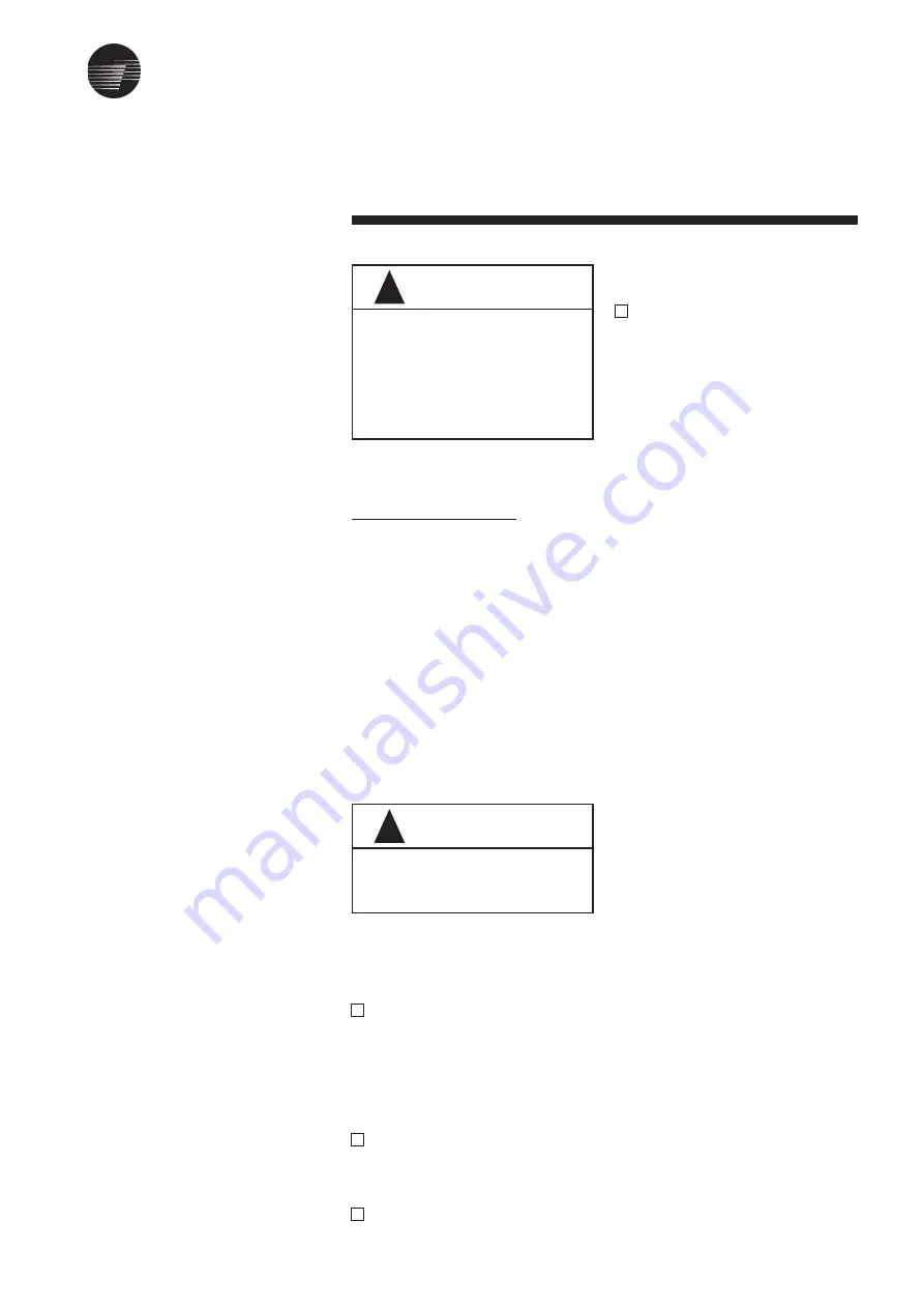
DO NOT LIFT THE UNIT WITHOUT
TEST-LIFTING FOR BALANCE AND
RIGGING. DO NOT LIFT THE UNIT
ABOVE PERSONNEL. FAILURE TO
OBSERVE THESE WARNINGS MAY
RESULT IN PERSONAL INJURY,
DEATH OR EQUIPMENT DAMAGE.

WARNING

!

CHECK THAT THE SUPPORTING
STRUCTURE IS STRONG ENOUGH
TO SUPPORT UNIT WEIGHT.

WARNING

!

Unit Installation

5

Unit Location Recommen-
dations

When selecting and preparing of the
unit operating location, consider the
following:
1. LWHA shall be installed for hori-

zontal application only.

2. Available power supply must agree

with electrical data on unit
nameplate.

3. Consider the weight of the unit .
4. Allow sufficient space for the recom-

mended clearances. Refer to
Figure 1.

5. Installer must provide suspension

rods (threaded) for ceiling mounted
unit.

6. All unit must be installed level.
7. Coil piping and condensate drain

requirements must be considered.
Allow room for proper ductwork and
electrical connections. Support all
piping and ductwork independently
of unit to prevent excess noise and
vibration.

Lifting / Rigging Recom-
mendations

Before preparing the unit for lifting,
estimate the approximate center of
gravity for lifting safety. Because of
placement of internal components, the
unit weight may be unevenly
distributed, with more weight in the coil
area. Before hoisting unit into position,
be sure that a proper rigging method
is used, with straps or slings and
spreader bars for protection and safety
during lifting. Always test-lift the unit to
determine exact unit balance and
stability before hoisting it to the
installation location.

MOUNTING

Unit Suspension - Typical

If the unit will be suspended, use
suspension mouting kit to isolate the
unit from structure. This is usually
accomplished through the use of
spring or rubber type vibration
isolators. The units are designed to be
suspended from ceiling on threaded
rod size 3/8” or 1/2”(M12), furnished by
the installing contractor. Four external
mounting lugs are provided at bottom
of the unit. The false ceiling opening
must be large enough for future
maintenance.

 pan. Refer to drain trap sketch in the
    piping section.
4. Connect the ductwork to the unit.

Auxiliary Drain Pan

A field fabricated auxiliary drain pan
may be installed under the unit, and
when condensate overflow may cause
damage. This drain pan will eliminate
any excess condensation that may be
due to extreme humidity or an
obstructed drain in the primary drain
pan. Drain lines from this pan must be
installed, but should not be connected
to the primary drain line from the unit.
Isolate the auxiliary drain pan from both
the air handler and the structure.

Air Filters

LWHAs are shipped with 2” Washable
filters installed in the unit as standard.
For filter dimension and quantity, refer
to General Specification. Filter loading
method is sliding type and accessible
from both sides.

Duct Connections

The Inlet and Discharge air duct
connections to the unit should be
made with a flexible material
minimizing noise and vibration.
Typically, about 3 inches(75mm) is
needed for this connection to rigid
ductwork.
Duct turns and transitions must be
made carefully to minimize air friction
losses. Avoid sharp turns and use
splitters or turning vanes when elbows
are necessary. Discharge (supply)
ductwork should run in a straight line,
unchanged in size or direction, for at
least a distance of 1-1/2 fan diameters
(see General Specification, for fan
diameter).
The return duct should be sized to the
same dimensions as the return inlet
the return inlet of the unit.
All ductwork should be properly
insulated to prevet condensation and
heat loss.

To install unit complete the
following:

1. Determine the unit mounting hole

dimensions. Prepare the hanger
rod isolator assemblies (provided
by installing contractor) and install
them in the selected area. Threaded
rods are recommended for leveling
the unit.

2. Hoist the unit to the suspension rods

and attaché with washers and lock
nut. Refer to figure 2, for specific
mounting details.

3. Level the unit for proper coil drainage

and condensate removal from drain

Summary of Contents for LWHA

Page 1: ...TRANE TRANE R Installation Operation Maintenance Belt Driven Direct Drive Low Height Air handler LWHA Model LWHA BC SVX002 E4 Sept 2011 ...

Page 2: ...the carrier immediately by phone or any registered mail Notify the local Trane Sales Office Conceal damage must be reported within 15 days of delivery Check the unit nameplate to confirm that the proper unit was shipped Available power supply must be compatible with electrical characteristics specified on component nameplates Installation This manual covers the installation operation and maintenan...

Page 3: ...TRANE Contents Model Nomenclature General Specification Unit Installation Dimension Data Electrical Wiring Diagram Operation Start Up Maintenance Trouble Analysis ii 1 2 3 4 5 8 9 12 13 14 15 17 18 20 ...

Page 4: ... 22 23 24 25 26 27 28 29 30 X None For Direct Drive Code Dia KW A 11 0 18 B 14 0 37 C 19 0 75 D 24 1 1 1 5 E 28 2 2 3 G 90 N 132 X None A 63 H 95 O 140 B 67 I 100 P 150 C 71 J 106 Q 160 D 75 K 112 R 170 E 80 L 118 S 180 F 85 M 125 T 190 Model Belt Driven Direct Driven LWHA 013 LWHA 023 LWHA 033 LWHA 043 LWHA 053 LWHA 063 A 8 8 Single B 9 7 Single B 9 7 Single C 9 7 Twin D 10 8 Twin D 10 8 Twin E K...

Page 5: ...e 1 Yes 0 Future Use 0 Future Use 0 Future Use Service Indicator E Revised Fan Model 2 LWHA Model Nomenclature Digit 15 Digit 16 Digit 17 Digit 18 19 20 21 Digit 22 Digit 23 Digit 24 Digit 25 Digit 26 Digit 27 Digit 28 Digit 29 Digit 30 A 1 A 1 2 0 0 4 X L 2 X 0 0 0 E L W H A 0 1 3 E A 2 A A A A A 1 A 1 2 0 0 4 X L 2 X 0 0 0 E 1 2 3 4 5 6 7 8 9 10 11 12 13 14 15 16 17 18 19 20 21 22 23 24 25 26 27...

Page 6: ... 18 0 37 0 75 0 7 1 2 2 0 2 5 5 0 10 4 254 10 787 4 31 0 2 2 15 LWHA 023 LWHA 033 LWHA 043 LWHA 053 LWHA 063 1750 2973 1118x523x1008 120 240x270 63 5 18 62 12 66 0 80 15 91 47 6 73 21 43 14 57 0 92 4 7 14 0 39 11 48 4 36 0 28 0 64 1 9 9 7 1750 0 37 0 75 1 1 1 2 2 0 2 5 5 0 10 4 14 6 355 6 14 914 4 36 0 33 3 5 2042 3469 1271x523x1008 130 240x270 76 22 24 15 12 0 95 24 22 72 4 88 5 25 95 17 64 1 11 ...

Page 7: ...TRANE 4 General Specification LWHA 013 thru 063 EE ...

Page 8: ...mounting lugs are provided at bottom of the unit The false ceiling opening must be large enough for future maintenance pan Refer to drain trap sketch in the piping section 4 Connect the ductwork to the unit Auxiliary Drain Pan A field fabricated auxiliary drain pan may be installed under the unit and when condensate overflow may cause damage This drain pan will eliminate any excess condensation th...

Page 9: ...FIGURE 3 USE BACK UP WRENCH WHEN ATTACHING PIPING TO COILS ON THERADED CONNECTIONS Condensate Drain Con nections CAUTION FAILURE TO PROVIDE ADEQUATE CONDENSATE PIPING MAY RESULT IN WATER DAMAGE TO THE EQUIPMENT OR BUILDING DRAIN TRAPS MUST BE PRIMED IF THEY ARE NOT THE TRAP IS ESSEN TIALLY NON EXISTENT AND DRAIN PAN WILL LIKE OVERFLOW The threaded condensate drain connection is provided on the coi...

Page 10: ...TRANE Unit Installation 7 ...

Page 11: ...TRANE Unit Installation 8 ...

Page 12: ...TRANE 9 Dimension Data Low Height Air Handling Unit Double Wall Direct Driven LWHA 013 023 LH Coil ...

Page 13: ...TRANE 10 Dimension Data Low Height Air Handling Unit Double Wall Direct Driven LWHA 033 043 053 LH Coil ...

Page 14: ...TRANE 11 Dimension Data Low Height Air Handling Unit Double Wall Belt Driven LWHA 013 023 033 LH Coil ...

Page 15: ...TRANE 12 Dimension Data Low Height Air Handling Unit Double Wall Belt Driven LWHA 043 053 063 LH Coil ...

Page 16: ...iring diagrams for LWHA Motors up to 2 2 kW or 3 0 HP are suitable for Direct On Line starting Larger Motors are suitable for both autotransformer and Star Delta starting Fan Motor Wiring Termination Three Terminal Fan Motor Wiring Termination Six Terminal ...

Page 17: ... parallel j Check belt tension as per instruction given in the maintenance section Start Up procedures After completing all items under Pre Start Up the unit may be started and the following checks and adjustments performed a Bump start the motor to check the direction of rotation If the rotation need to be changed stop the motor completely and change the direction of rotation by changing the line...

Page 18: ... thoroughly before re installing in the units Do not rub or wring Washable filters can also be cleaned by blowing with compressed air in opposite direction of filter airflow Fan Belt Tension Note Fan belt tension should be checked at least twice during the first day of operation since there is a rapid decrease in tension until belts are run in Proper belt tensioning is required to ensure maximum b...

Page 19: ...TRANE 16 Maintenance Figure 6 Belt Tension Measurement Table1 Deflection Force K ...

Page 20: ...sis is particularly given to the importance of periodic checks on the unit operating parameters as well as on preventative maintenance which reduces the cost of owning the unit by avoiding serious and costly breakdown Fan Belt Maintenance Clean fan belts and pulleys with a dry cloth Oil and grease must be kept off belts The use of a belt dressing is not recommended When replacing belts use a match...

Page 21: ... DISCONNECT ELECTRICAL POWER SOURCE AND ALLOW ALL ROTATING EQUIPMENTTO STOP COMPLETELY BEFORE INSPECTING OR SERVICING THE UNIT FAILURE TO DO SO MAY RESULT IN PERSONAL INJURY OR DEATH FROM ELECTRICAL SHOCK OR MOVING PARTS WARNING DISCONNECT ELECTRICAL POWER PRIOR TO ACCESS INTO A FAN DUCTWORK EVEN WHEN LOCKED OUT ELECTRI CALLY FANS MAY CAUSE INJURY OR DAMAGE IF THE IMPELLER IS SUBJECT TO WINDMILLIN...

Page 22: ...on Motor mounting bolts loose Worn motor bearings Fan rubbing on fan cover Recommended Action Adjust tension Replace bearing Correct alignment Check shaft level Replace fuse or reset circuit breaker Check and reset overload Check wiring with diagram supplied on unit Compare actual supply power with motor nameplate recommendations Contact power company for adjust ments Check that motor and driver r...

Page 23: ...rk too short Drain pipe choked Improper or no U trap Water carry over due to high velocity Recommended Action Check belt tension and overhung load Replace sheave with larger one Adjust belt tension Replace belt or belt set Check sheave alignment Replace sheaves Replace sheaves Realign drive Check for leaky bearings Clean belts and sheaves Adjust tension Remove obstruction or realign drive for clea...

Page 24: ...e has a policy of continuous product and product data improvement and reserves the right to charge design and specifications without notice Only qualified technicians should perform the installation and servicing of equipment referred to in this publication Trane www trane com For more information contact your local district office TRANE ...

Reviews: