

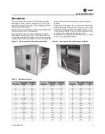


Installation
CLCH-SVX08C-EN
15
Installing Indoor Flue Stacks
Gas heat sections for indoor air handlers require a field-
engineered and field-installed flue stack. Local codes and
practices vary throughout the country. The engineer
should size the flue based on MBh output, horizontal and
vertical run lengths, type of flue material, NFPA 54 Fuel Gas
Code, and local codes. The flue should be designed for 800
degrees F (430 degrees C). If horizontal runs over 20 feet or
other static-increasing transitions are necessary, a flue
booster fan will be required.
Install according to local codes. See connection sizes in
.
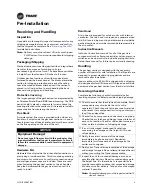
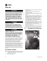
Installing Rain Hood/Combustion Air Inlet
Rain hoods are only required on an outdoor unit with an
internal vestibule. Depending on unit size, the combustion
air opening will be in the access door or in the side panel.
A unit with an external vestibule has the combustion air
opening in the floor of the vestibule and does not require
a rain hood, unless excessive snowdrifts are expected.
Rain hoods for the combustion air opening ship loose and
must be installed at the job site. The assembly consists of
the hood, butyl tape and number 10 screws.
•
Install butyl tape between the hood and the side panel
or door panel (see
).
•
Locate the bottom edge of the hood 2 3/8 inches below
the bottom edge of the inlet air opening and center the
hood left-to-right over the inlet air opening (see
).
•
Install the hood to the unit with number 10 screws.
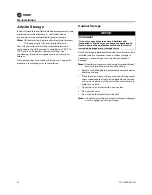
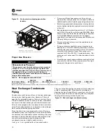
Installing Flue Stack for Hurricane
Applications
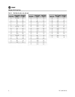
Table 5.
Flue connection sizes for gas heat sections
Gas Output (MBh)
Flue Size (inches)
200, 320, 360, 560
8 × 8
300
9 × 9
700, 860, 1000
12 × 12
1250, 1500, 1750
10 × 10
2000, 2400
14 x 14
Figure 7. Installation of rain hood for combustion air
opening
Hood
Butyl tape
Figure 8. Center inlet air opening
Figure 9.
Flue stack installation for hurricane
applications
Hinge
side
2 3/8 in.
Center hood left-to-right
over opening
Combustion
air opening
Rain hood
Access door
Airflow
Attach the gas heat flue duct
to the L angles on both sides
Gas heat flue
See note
L bracket
Right side view
Note:
When installing flue, leave enough clearance to avoid roof’s edge and anything above the roof.
#10 x 3/4-in. self-drilling
sheet metal screws