


7
FWD-SVX01D-E4
It is possible to avoid using the 2
angle brackets B supplied with the
unit and mount it using just the
threaded rods D and the 2 shaped
bars E. In both cases isolators can be
installed between the nuts C and the
angle brackets B or shaped bars E, to
reduce transmission of vibrations to
the building’s structure.
Warning.
Since the condensate
tray is sloped to facilitate flow of
condensates, the unit must be
positioned absolutely level in both
directions.
Installation on the ground
The unit can be installed on the
ground, but make sure the
condensate can be drained properly.
Ensure it is installed on vibration
isolators and that it is level in both
directions.
Hydraulic connections
It is easy to remove the electric
cabinet to facilitate access to the
hydraulic connections. Operating
limits of pressure must not exceed
1.5MPa.
Installation procedure
- Define the layout of the lines so
that they are as short as possible.
- Limit pressure losses in the lines
caused by pinching, too many
bends and bending radii that are
too small.
- Connection of water inlet and out-
let lines:
The coil is connected by means of
3/4” female ISO R7 connectors.
Warning.
Limit the tightening
torque applied to the connector
nuts to prevent deformation of the
piping and seals (risk of leaks).
Installation
Ceiling installation
Preparation of the ceiling and
installation of the unit
A template for drilling into the ceiling
to fix the threaded rods is printed on
the cover of the unit’s packaging.
The angle brackets can also be used
to determine the drilling hole
distances.
Access must be provided on the
water connection end to facilitate
installation, maintenance and access
to the cabinet.
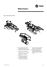
Four 8 mm diam. threaded rods must
be securely fixed into the building’s
slab or structure. Screw a nut A
(Figure 2) sufficiently high onto each
threaded rod. Put the angle brackets B
in place by holding them using a
second nut C. Make sure the angle
brackets are level in both directions
using the bottom nuts C. Once they
are perfectly level insert the FWD unit
and let the angle brackets support it.
Use the top nuts A to tighten the unit
against the corner brackets.
➀
➀
A
B
Figure 2 : Angle brackets
Figure 3 : Recommended clearances
Summary of Contents for FWD 08
Page 1: ...Ductable water unit FWD 08 12 20 30 45 Installation Operation Maintenance FWD SVX01D E4 ...
Page 11: ...11 FWD SVX01D E4 ...
Page 12: ...12 FWD SVX01D E4 ...
Page 13: ...13 FWD SVX01D E4 ...
Page 14: ...FWD SVX01D E4 Space requirement plans 14 ...
Page 15: ...FWD SVX01D E4 15 ...
Page 19: ...19 FWD SVX01D E4 Notes ...


