Disassembly
14
CVHS-SVN04E-EN
3. Remove the control panel if necessary. Also,
disconnect and remove the unit mounted starter, if so
equipped. See
“Control Panel Removal,” p. 12
instructions.
4. Remove the economizer vent pipe flange hex head
screws at the compressor and economizer connection.
See
for instructions.
5. Before removing the compressor/motor assembly,
consult with a rigging specialist. Employ rigging
specialist procedures when removing the compressor
motor/assembly.
Important:
Two M20 swivel D-rings are required for
lifting the compressor assembly (metric
threads).
6. Remove the suction elbow.
a. The suction elbow has lifting tabs. You will need a
lifting clevis to remove the elbow. A Crosby screw
pin shackle, model S-209, stock number 1018482
with a 5/8-in. pin is acceptable as shown in
.
Figure 9.
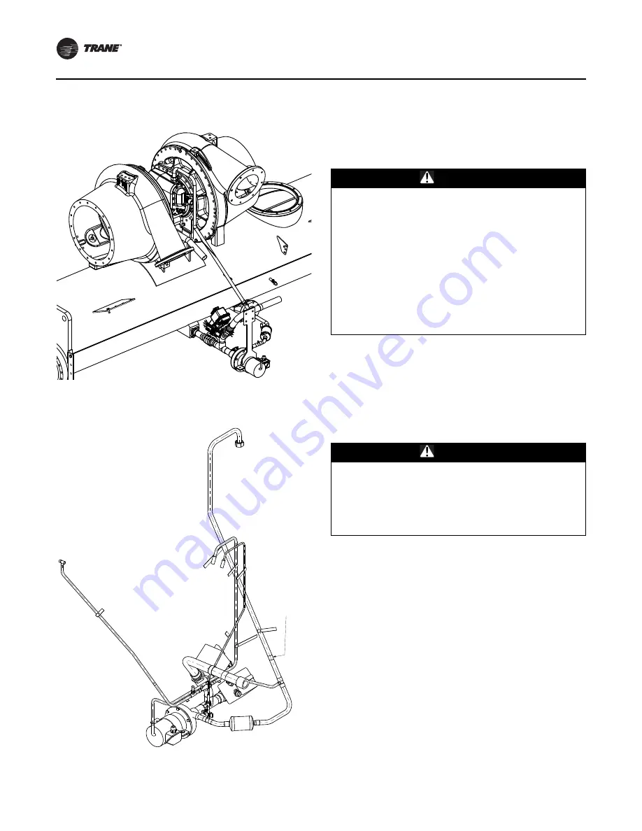
Lubrication system
Figure 10.
Lubrication system detail
Cut for
coupling
WARNING
Heavy Objects!
Failure to follow instructions below or properly lift
component could result in component dropping and
possibly crushing operator/technician which could
result in death or serious injury, and equipment or
property-only damage. Ensure that all the lifting
equipment used is properly rated for the weight of the
component being lifted. Each of the cables (chains or
slings), hooks, and shackles used to lift the component
must be capable of supporting the entire weight of the
component. Lifting cables (chains or slings) may not be
of the same length. Adjust as necessary for even
component lift.
WARNING
Improper Use of Elbow Lifting Tab!
Using the elbow lifting tab to lift chiller could result in
chiller dropping which could result in death, serious
injury, or equipment damage. Do NOT lift chiller using
elbow lifting tab. Elbow lifting tab and approved clevis
are used ONLY when removing elbow from chiller.


