background image

8

 CDQ-SVX01A-EN

Wiring

CAUTION
Do Not Install VFDs!

Do not install a variable-frequency 
drives (VFDs) to control wheel 
speed. This may result in failure of 
the wheel motor. 

CAUTION
Factory-Installed Wiring!

Use caution when penetrating unit 
casing. Factory wiring may be routed 
in the side panels of the module. 
Misplaced penetrations may result in 
damage to the wiring. 

CAUTION
Penetration Leaks!

Properly seal all penetrations in unit 
casing. Failure to seal penetrations 
from inner panel to outer panel may 
result in unconditioned air entering 
the module, and water infiltrating 
the insulation, resulting in 
equipment damage. 

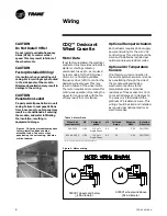
Figure 1. CDQ wheel modules may have 
factory-installed ribbon cables 
attached inside. Take care when 
penetrating the unit casing. Modules 
will be labeled.

CDQ™ Desiccant 
Wheel Cassette

Motor Data

If not factory-installed, the electrical 
contractor must provide and install a 
starter or starting contactor, 
disconnect, fuses, etc., as required 
by local codes, for the CDQ wheel 
motor. Do not install a variable 
frequency drive (VFD) to control the 
desiccant wheel speed. This may 
result in failure of the wheel motor. 
The motor requires air movement for 
continuous operation. Operating the 
wheel for long periods with the fan 
off may result in motor failure. 

Table 1. Motor Data

Wheel Size 

(nominal cfm)

HP

Voltage/

phase

HZ

Full Load 

Amps

Rotation   

RPM

Rotation 

Direction

500-5000

1/80

115 Volt 

Single Phase

60

0.3

       2.30 

CW/CCW*

6000-40,000

1/80

115 Volt 

Single Phase

60

0.3

       4.50 

CW/CCW*

*Motors are wired for counter clockwise rotation

Figure 2. Motor wiring


5000C1 wheels and below 
 < 

48in diameter

6000C1 wheels and above 
 

>54in diameter

Optional Damper Actuators

Each actuator requires 24 Vac supply 
power and wiring for the 2–10 Vdc 
control signal. This wiring should be 
sized and installed as required per 
national and local electrical codes.

Optional Air Temperature 
Sensors

If not factory-wired, connection to 
the air temperature sensors is made 
by penetrating through the side of 
the module wall and making 
electrical connections to the 
temperature sensor. Nominal 
resistance of these sensors is 1,000 
ohms at 32 degrees F (0 degrees C). 
The sensor is a thermistor with a 
platinum 375 resistance curve. This 
wiring should be sized and installed 
as required per national and local 
electrical codes.

Summary of Contents for CDQ

Page 1: ...Installation Operation Maintenance CDQ Desiccant Wheels for Climate Changer Air Handlers June 2006 CDQ SVX01A EN Part No X39641062010...

Page 2: ...on which if not avoided could result in death or serious injury CAUTION indicates a potentially hazardous situation which if not avoided may result in minor or moderate injury It may also be used to a...

Page 3: ...his process is accomplished without the need for a second regeneration air stream The addition of the CDQ desiccant wheel to the system enhances the dehumidification performance of the traditional coo...

Page 4: ...ccant Wheel Cassette 8 Routine Maintenance Cleaning the Desiccant Wheel 9 Cleaning the Motor 10 Cleaning the Module 10 Bearing and Motor Lubrication 10 Drive Belt Tension 10 Service and Repair Procedu...

Page 5: ...tor nameplate and contact your local fan motor manufacturer representative for assistance Factory Mounted Controls Small items that cannot be factory mounted will ship inside the control enclosures La...

Page 6: ...ersonnel electrical interlocks that automatically disconnect power to the lights are provided at all unit entry points to equipment where lights are located WARNING Equipment Damage From Ultraviolet U...

Page 7: ...lt Adjustment Replacement on page 16 5 Start and stop the wheel several times to confirm seal adjustment and proper belt tracking on the wheel rim WARNING Hazardous Voltage Disconnect all electric pow...

Page 8: ...rol the desiccant wheel speed This may result in failure of the wheel motor The motor requires air movement for continuous operation Operating the wheel for long periods with the fan off may result in...

Page 9: ...ebris exiting the wheel In most instances this should adequately clean the wheel In the event the wheel is subject to an aerosol smoke or other material that coats the wheel it can be washed with wate...

Page 10: ...tions regarding use of the product 4 Rinse any cleaning product thoroughly from the module walls The use of a water stream from a garden hose or high pressure washer is not recommended Saturation of t...

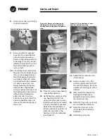
Page 11: ...r removal of old bearing and installation of new bearing 1 Remove belt from motor and wheel 2 Support wheel with wooden blocks on both sides of the wheel see Figure 3 Figure 3 Wooden blocks support wh...

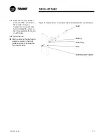
Page 12: ...gure 9 Remove snap ring 11 Clean the hub and new bearing races before installing 12 Gently tap the outer race of the new bearings into the hub using a hammer making sure that the bearing is not cocked...

Page 13: ...e necessary to loosen the shaft bolts and adjust the wheel so that it is equidistant from posts on both sides 20 Install the belt 21 Start up unit and check wheel for clearance Seals on the short post...

Page 14: ...gure 17 Remove bolts securing bearing 7 Remove the bearing Use a bearing puller if necessary 8 Clean shaft and install new bearing on shaft insuring that set screws line up with flats on the shaft 9 I...

Page 15: ...s necessary Flange bearing units have jack bolts see Figure 19 Pillow block bearing units require shims to adjust the bearing up or down see Figure 20 Retighten bearing mounting bolts once alignment i...

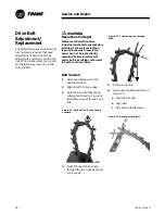
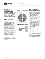
Page 16: ...to ensure the power can not be inadvertently energized Failure to disconnect power before servicing could result in death or serious injury Belt Tension 1 Disconnect all power to the desiccant wheel 2...

Page 17: ...s this may cause the wheel not to turn or overload the motor To minimize air the leaks from one side to the next the diameter seals should be adjusted to come in full contact with the wheel face see F...

Page 18: ...electrical components have a qualified licensed electrician or other individual who has been trained in handling live electrical components perform these tasks Failure to follow all of the recommended...

Page 19: ...y be defective Replace Refer to unit name plate for correct value Excessive friction at the seals Re adjust the diameter seals per the Seal Adjustment procedure Drive belt is broken Inspect visually R...

Page 20: ...e or e mail us at comfort trane com Literature Order Number CDQ SVX01A EN File Number SV CDQ SVX01A EN 606 Supersedes New Trane has a policy of continuous product and product data improvement and rese...

Reviews: