Trane BCHC Installation & Operation Manual Download Page 4

4

BCXC-SVX01A-EN

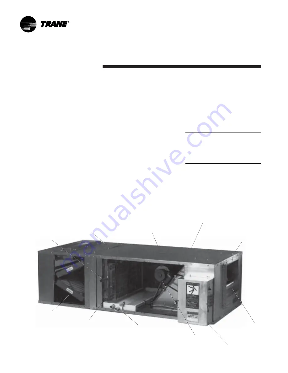
Figure I-GI-1. Blower coil air handler unit components. Model BCHC, horizontal unit, is shown.

Installation

General
Information

Blower Coil General
Information

Blower coil units are draw-thru air
handlers for cooling load conditions of
400-3000 cfm. Units are available in
either horizontal (model BCHC) or vertical
(model BCVC) configurations. Horizontal
units are typically ceiling suspended via
threaded rods. Knockouts are provided in
all four corners to pass the rods through
the unit. Horizontal units can also be floor
mounted. Vertical units are typically floor
mounted. They have a side inlet for easy
duct connection, and do not require a field
fabricated inlet plenum. Vertical units ship
in two pieces and can be set up in either a
pre-swirl or counter-swirl configuration.

Basic unit components consist of a water
coil, condensate drain pan, filter, duct
collars, one fan wheel, and motor with
drive. See Figure GD-1. Drive compo-
nents consist of sheaves, belt, and motor.
The coil, drain pan, and motor/drive
assembly can easily be field-converted
from right hand to left hand configura-
tions or vice versa.

Two, four, or six-row main coils are
available for either hydronic cooling or
heating. Four or six-row direct expansion
(DX) coils are also available for cooling.
An optional one, two, four, or six-row
heating coil is available factory-installed
in either the preheat or reheat position.
Also, a one-row preheat steam is
available.

All units have an internal flat filter frame
for one or two-inch filters. An optional
angle filter box (two inch only), mixing
box, bottom/top filter access box, or
combination angle filter mixing box is
available.

In addition, all units are available with
either a basic or deluxe piping package
option that includes a variety of control
valve sizes in two or three-way configura-
tions. The basic package consists of a
control valve and stop (ball) valves. The
deluxe package consists of a control
valve, a stop (ball) valve, a circuit setter,
and strainer.

Belt-drive motors range from 

1

/

3

 to 3

horsepower in a wide range of voltages.

All motors have internal thermal and
current overloads, permanently sealed
ball bearings, and a resilient cradle mount
to reduce noise and vibration transmis-
sion.

Variable pitch sheave drive kit options
help make it possible to more accurately
select design static pressure. For addi-
tional flexibility, 115 volt single phase, two
speed motors are optional.

Note: Sheaves are factory set in the
middle of the range.Field adjustment of
sheaves, motor, and belt are required to
arrive at desired rpm. Refer to the
original sales order and Table GD-1 for
drive information.

Units may have no controls (4 x 4 junction
box) or any of four different control types:
1. control interface
2. Tracer ZN010
3. Tracer ZN510
4. Tracer ZN520

All control options are factoryinstalled
and tested.

Two, four, or six–row
main coil with copper
tubes and enhanced
aluminum fins

Internal filter frame
accomodates one or
two–inch filters

Galvanized steel
cabinet in 14, 18, 22,
and 28 inch heights

Unit sizes 12, 18, 24, 36,
54, 72, and 90 MBh

Knockouts in all four
corners for hanger
rods

Angle filter option
and/or mixing box
accomodates 2–
inch filters

Internal one or two–
row auxiliary coil in
preheat or reheat
position

Main and auxiliary
drain connections on
same side of unit

1

/

4

 to 3 hp motor with

drive selections from
400 to 1800 rpm

Control box

Forward curved fan

Summary of Contents for BCHC

Page 1: ...BCXC SVX01A EN Installation Operation andMaintenance September 2002 Blower Coil Air Handler Air Terminal Devices 400 to 3000 cfm Models BCHC and BCVC AO and later design sequence ...

Page 2: ...cidents Sample Warnings and Cautions WARNING Hazardous Voltage Before servicing unit disconnect all electrical power including remote disconnects Follow proper lockout tagout procedures to ensure power cannot be inadvertently energized Failure to disconnect power before servicing can cause death or serious injury CAUTION Use copper conductors only Unit terminals are not designed to accept other co...

Page 3: ... Guide for Tracer ZN520 Unit Controller CNT SVX04A EN Blower Coil Air Handler Catalog UNT PRC003 EN Installation 2 General Information 2 Pre installation Considerations 7 Dimensions Weights 9 Mechanical Requirements 16 Electrical Requirements 20 Installation Procedure 23 Pre Startup Requirements 27 Operation 29 General Information 29 Sequence of Operation 32 Maintenance 43 Maintenance Procedures 4...

Page 4: ... or combination angle filter mixing box is available In addition all units are available with either a basic or deluxe piping package option that includes a variety of control valve sizes in two or three way configura tions The basic package consists of a control valve and stop ball valves The deluxe package consists of a control valve a stop ball valve a circuit setter and strainer Belt drive mot...

Page 5: ...er U 4 row DX 3 16 distributor V 6 row DX 3 16 distributor W 4 row DX 1 4 distributor X 6 row DX 1 4 distributor Digit 15 Unit Coil 2 all coils are hydronic unless stated otherwise 0 none A 1 row heating B 2 row heating C 4 row heating D 6 row heating E 2 row cooling F 4 row cooling G 6 row cooling H 2 row heating cooling with autochangeover J 4 row heating cooling with autochangeover K 6 row heat...

Page 6: ...lied valve 2 pos n o J field supplied modulating valve Digit 31 Coil 2 Control Valve Cv 0 none A 3 3 Cv 1 2 modulating 1 2 pipe B 3 3 Cv 1 2 modulating 3 4 pipe C 4 0 Cv 1 2 modulating 3 4 pipe D 6 0 Cv 1 modulating 1 pipe E 8 3 Cv 1 modulating 1 pipe F 9 0 Cv 11 4 modulating 11 4 pipe G 3 5 Cv 1 2 2 position 1 2 pipe H 4 4 Cv 1 2 2 position 1 2 pipe J 7 0 Cv 3 way valve 1 2 position 1 pipe OR 6 0...

Page 7: ... ordering and shipping information to verify the correct unit is received Jobsite Storage Recommendations This unit is intended for indoor use only To protect the unit from damage due to the elements and prevent it from possibly becoming a contaminant source for IAQ problems store the unit indoors If indoor storage is not possible the Trane Company makes the following provisions for outdoor storag...

Page 8: ...nded clearances for routine maintenance and service Refer to unit submittals for dimensions Allow one and one half fan diameters above the unit for the discharge ductwork WARNING Improper Unit Lift Test lift the unit approximately 24 inches to verify proper center of gravity lift point To avoid dropping of unit reposition lifting point if unit is not level Failure to properly lift unit can result ...

Page 9: ... 80 77 4 24 18 00 28 00 46 00 16 09 22 00 13 56 12 56 1 30 3 00 10 79 14 79 7 72 3 58 9 00 104 1 36 18 00 40 00 46 00 16 09 34 00 13 56 12 56 1 30 3 00 10 79 14 79 13 72 3 57 9 00 121 6 54 22 00 40 00 49 00 20 09 34 00 13 56 12 56 0 72 3 00 10 79 14 79 13 72 4 21 10 43 138 9 72 22 00 48 00 49 00 20 09 40 00 13 56 12 56 0 72 4 00 10 79 14 79 17 72 4 18 10 43 152 2 90 28 00 48 00 52 00 26 09 40 00 1...

Page 10: ...09 34 00 13 56 12 56 1 30 3 00 10 79 14 79 13 72 3 57 9 00 18 00 185 9 54 72 50 40 00 47 00 20 09 34 00 13 56 12 56 0 72 3 00 10 79 14 79 13 72 4 21 10 43 22 00 206 4 72 72 50 48 00 47 00 20 09 40 00 13 56 12 56 0 72 4 00 10 79 14 79 17 72 4 18 10 43 22 00 228 2 90 81 50 48 00 50 00 26 09 40 00 13 56 12 56 1 66 4 00 10 79 14 79 17 72 4 81 15 61 28 00 258 4 30 00 11 25 vertical counter swirl config...

Page 11: ...0 48 00 12 81 31 56 72 5 90 27 90 27 56 48 00 12 85 31 56 84 1 combination angle filter mixing box mixing box angle filter box NOTES 1 ALL DIMENSIONS ARE IN INCHES 2 MIXING BOX SHIPS ASSEMBLED FOR FIELD INSTALlatION 3 LINKAGE BETWEEN DAMPERS IS FACTORY INSTALLED INSIDE MIXING BOX OPPOSITE DRIVE SIDE DRIVE ROD ON BACK DAMPER MAY BE EXTENDED THRU KNOCKOUT FOR EXTERNALLY MOUNTED ACTUATOR TO ADJUST LO...

Page 12: ...28 00 9 98 2 01 21 98 3 01 17 24 18 00 28 00 14 23 1 89 23 23 2 38 18 36 18 00 40 00 14 23 1 89 33 73 3 13 25 54 22 00 40 00 18 23 1 89 33 73 3 13 28 72 22 00 48 00 18 23 1 89 42 73 2 63 32 90 28 00 48 00 23 23 1 89 41 23 3 38 37 7 17 AIR FLOW 97 RIGHT SIDE FILTER ACCESS PANEL FILTER AIR FLOW TOP FILTER NOTES 1 DIMENSIONS ARE IN INCHES 2 ROTATE 180 FOR TOP ACCESS right side view top view 3 SECTION...

Page 13: ...6 79 10 50 7 75 0 03 10 0 18 14 06 19 88 10 13 8 79 10 50 7 75 0 03 10 8 24 18 06 21 25 7 63 6 29 13 50 12 63 0 80 11 3 36 18 06 27 25 13 63 12 29 13 50 12 63 0 80 12 8 54 18 06 27 25 13 63 11 67 13 50 12 63 0 22 16 0 72 18 06 27 25 13 63 11 67 13 50 12 63 0 22 17 4 90 18 06 27 25 13 63 11 67 13 50 12 63 1 16 19 2 90 ARE HINGED top view front view right side view ...

Page 14: ...Supply Return 12 14 00 24 00 12 06 18 04 2 98 34 1 0 0 75 18 14 00 28 00 12 06 22 04 2 98 37 1 0 0 75 24 18 00 28 00 16 06 22 04 2 98 40 1 5 1 00 36 18 00 40 00 16 06 34 04 2 98 48 1 5 1 00 54 22 00 40 00 20 06 34 04 2 98 50 2 0 1 00 72 22 00 48 00 20 06 42 04 2 98 56 2 0 1 00 90 28 00 48 00 26 06 40 04 3 98 63 2 5 1 25 ACCESS PANEL FILTER ACCESS HEATING COIL 21 00 0 97 0 97 H A B W C C NOTES 1 FI...

Page 15: ...iping Piping Package Dimensions in Piping nominal actual Package size size A B C D E F 2 way 0 50 0 625 12 025 2 650 12 625 5 650 na na 1 00 1 125 13 295 4 260 13 220 9 288 3 020 na 3 way 0 50 0 625 12 088 2 097 12 688 4 497 6 351 6 351 0 75 0 875 15 623 1 750 15 313 6 290 6 701 6 701 1 00 1 125 13 370 3 690 13 210 9 060 9 813 9 813 1 25 1 375 16 885 3 738 16 410 10 023 3 052 10 520 B B A AB A E T...

Page 16: ... Align the fan outlet properly with the ductwork to decrease duct noise levels and increase fan performance Check total external static pressures against fan characteris tics to be sure the required airflow is available throughout the ductwork To achieve maximum acoustical perfor mance minimize the duct static pressure setpoint Figure I MR 1 Recommended drain trap installation for draw thru units ...

Page 17: ...en piping to the coil Note If the unit has the high capacity cooling coil option you must insulate both the bottom and top of the unit casing CAUTION Potential coil freeze condition Make provisions to drain the coil when not in use to prevent coil freeze up Piping Packages Piping packages ship separate for field installation and have sweat type connections Interconnecting piping is field provided ...

Page 18: ...e bulb should be firmly attached to a straight well drained horizontal section of the suction line The external equalizer line should be inserted downstream of the remote bulb Moisture indicating sight glass Install a moisture indicating sight glass in the liquid line between the expansion valve and filter drier The sight glass should be sized to match the size of the liquid line Filter drier Inst...

Page 19: ... diameter thermal expansion valve TXV liquid line filter drier solenoid valve sight glass distributor suction line Evaporator Coil with Standard Circuiting that matches the suction header connection 4 For the vertical riser use the tube diameter recommended by the condensing unit manufacturer Assure the top of the riser is higher than the evaporator coil 5 Arrange the suction line so the refrigera...

Page 20: ... wire are inside the control box connected to a non fused disconnect switch 3 If the unit has a electric heat power and ground connections are inside the electric heat control box connected to a non fused disconnect switch or terminal block Electrical Grounding Restrictions All sensor and input circuits are normally at or near ground common potential When wiring sensors and other input devices to ...

Page 21: ...ne fuses 5 Units with electric heat must not be run below the minimum cfm listed in the general data section 6 Electric heat is balanced staging 1 stage 100 2 stages 50 50 7 Electric heat is not available on 190 50 3 units Minimum Circuit Ampacity MCA and Maximum Fuse Size MFS Calculations for Units with Electric Heat Use these formulas to calculate the MCA and MFS Heater amps heater kW x 1000 hea...

Page 22: ...8 5 3 0 49 8 6 55 1 230 60 3 207 253 1750 1 2 22 2 4 12 8 3 4 26 3 0 18 6 1 0 28 3 6 23 0 1 5 29 4 8 33 4 2 0 34 6 2 43 6 3 0 49 8 6 62 0 460 60 3 414 506 1750 1 2 22 1 2 6 4 3 4 26 1 5 9 3 1 0 28 1 8 11 5 1 5 29 2 4 16 7 2 0 34 3 1 21 8 3 0 49 4 3 31 0 575 60 3 518 632 1750 3 4 20 5 1 1 7 5 1 0 22 5 1 4 9 0 1 5 31 1 9 13 3 2 0 36 2 5 17 9 3 0 49 3 3 23 7 220 50 1 198 242 1450 1 3 20 5 3 0 15 6 1 ...

Page 23: ...he hanger rod isolator assemblies which are field provided and install them in the ceiling Trane recommends using threaded rods to level the unit Consult the unit nameplate or the Dimensions and Weights section in this manual for the unit weight See Figure I IP 1 for proper horizontal unit installation 2 Remove motor access panels and filter access panels 3 Punch out the eight knockouts in the top...

Page 24: ...ided with legs that are field installed to help accomodate a U trap on the drain connection if necessary A field fabricated inlet plenum is not required The unit is shipped in two pieces and can be arranged in either a pre swirl or counter swirl inlet configuration See Figure I IP 4 Figure I IP 4 Typical vertical unit installation ...

Page 25: ...llation Mixing Box Installation Procedure 1 Support the mixing box independent of the unit in the horizontal position 2 Install the mixing box as a sleeve around the duct collar of the filter frame To attach the mixing box to the filter frame insert screws through the matching the holes on all sides of the mixing box and filter frame 3 Install the linkage following the procedure below Linkage Inst...

Page 26: ...tion Follow the procedure below to install the zone sensor module See Figure I IP 5 1 Note the position of the setpoint adjustment knob and gently pry the adjustment knob from the cover using the blade of a small screwdriver 2 Insert the screwdriver blade behind the cover at the top of the module and carefully pry the cover away from the base 3 To install the zone sensor module without a junction ...

Page 27: ...stem or Rover software to change the default values Follow the procedure below to operate the Tracer ZN controller in a stand alone operation 1 Turn power on at the disconnect switch option 2 Position the fan mode switch to either high low or the auto position 3 Rotate the setpoint dial on the zone sensor module to 55 F for cooling or 85 F for heating The appropriate control valve will actuate ass...

Page 28: ...mponent Overview Verify the fan and motor shafts are parallel Verify the fan and motor sheaves are aligned Check the belt tension for proper adjustment Adjust the belt tension if it is floppy or squeals continually Ensure the fan rotates freely in the correct direction Tighten locking screws bearing set screws and sheaves Ensure bearing locking collars do not wobble when rotated and correct torque...

Page 29: ... refer to the Trane publication number CNT IOP 1 or CNT SVX04A EN Tracer ZN010 Tracer ZN010 is a stand alone microprocessor controller Tracer ZN510 and ZN520 ZN510 can be used as either a stand alone or as part of a Trane Integrated Comfort System ICS In the stand alone configuration ZN510 or 520 receives operation commands from the zone sensor and or the auto changeover sensor on auto changeover ...

Page 30: ... input a a a AnalogInputs zone temperature a a a setpoint a a a fan mode auto high low a a a entering water a a a discharge air a a a outside air a generic a Note The generic input and output are for use with a Tracer Summit system only Table O GI 2 Tracer Controller Function Summary TracerController ZN010 ZN510 ZN520 Control Functions entering water temp sampling purge a a a timed override a a a ...

Page 31: ...atus a filterrun timediagnostic a a a fan status a a positiveprooffanstatusswitch a a 2 positioncontrolvalves a a a a modulatingcontrolvalves a a 2 positionmixingboxactuator a a a modulatingmixingboxactuator a 1 stage electric heat a a a a 2 stage electric heat a a Frostat protection DXcoils a a Note Units with a DX coil are provided with a DX cool relay if unit has the control interface or Tracer...

Page 32: ...re information on the setup of another BAS refer to the product specific literature from that manufacturer Occupied Mode When the controller is in the occupied mode the unit attempts to maintain the space temperature at the active occupied heating or cooling setpoint based on the measured space temperature the discharge air temperature Tracer ZN520 only the active setpoint and the proportional int...

Page 33: ...ed on the cooling capacity At 0 capacity all cooling capacities are off and the damper is at minimum position Between 0 and 100 capacity the cooling outputs are controlled according to modulating valve logic Tracer ZN520 only or cycled with 2 position valves As the load increases modulating outputs open further and binary outputs are energized longer At 100 capacity the cooling valve or damper is ...

Page 34: ...ng unoccupied mode the fan cycles be tween high speed and off with heating and cooling fan modes If the requested speed is off the fan always remains off During dehumidification when the fan is in auto the fan speed can switch depend ing on the error The fan speed increases as the space temperature rises above the active cooling setpoint Additional flexibility built into the control ler allows you...

Page 35: ...escontinuouslyatselectedspeed ContinuousFan modulatingcontrolvalveoptioncyclesasneeded Auto ZN010 fan 2 position damper cycle control valve cycle as Fan Cycling ZN510 needed in cooling fan cycles from off to high inheatingmodefancyclesfromofftolow when heating cooling is not required the fan is off the 2 positiondamperoptioncloses Auto ZN520 fancyclesbetweenhighandmedium andneverturnsoff unless th...

Page 36: ...d Operating Range and Factory Default Setpoints Tracer ZN010 ZN510 Setpoint Parameter DefaultSetting ValidOperatingRange Unoccupiedcoolingsetpoint 85 F 40 to 115 F Occupiedcoolingsetpoint 74 F 40 to 115 F OccupiedHeatingsetpoint 71 F 40 to 115 F Unoccupiedheatingsetpoint 60 F 40 to 115 F Coolingsetpointhighlimit 110 F 40 to 115 F Coolingsetpointlowlimit 40 F 40 to 115 F Heatingsetpointhighlimit 10...

Page 37: ...ure sam pling function periodically opens the two way valve to allow temporary water flow producing reliable entering water temperature measurement To ensure accurate unit changeover without sacrificing the benefits of 2 way 2 position valves Tracer ZN controllers periodically test the entering water temperature on all hydronic main coil changeover units Hydronic heating cooling changeover operati...

Page 38: ...O SO 9 Relationship Between Outdoor Temperature Sensors and Economizer Damper Position Tracer ZN520 Only ModulatingFreshAir Damper OutdoorAirTemperature OccupiedorOccupiedBypass OcupiedStandby Unoccupied Noneorinvalid Opentooccupied Opentooccupied Closed minimumposition standbymin pos Failed Opentoocc Opentoocc Closed min pos standby min pos Presentandeconomizer Economizing Economizing Openandecon...

Page 39: ... one minute The controller waits up to one minute after energizing a fan output to allow the differential pressure to build up across the fan Note 5 The table below shows the controller s response to low temperature detection condensate overflow and fan status diagnostics BIP Description Fan Valve Electric heat Damper BI 1 Lowtemperaturedetection off open off closed BI 2 Condensateoverflow off clo...

Page 40: ...y default for Tracer ZN010 and ZN510 controllers are main valve configured as normally closed aux valve configured as normally open 3 If the fresh air damper option is not ordered on the unit 2 pos damper is configured as none 4 Pin J1 2 can be configured for an exhaust fan with the use of Rover Software Factory default is none Table O SO 11 Analog Inputs AnalogInput Terminal Function Range ZN010 ...

Page 41: ...ted setpoint from Tracer or other building automation system However Rover service software can communicate with all Tracer ZN controllers These setpoint limits only apply to the occupied and occupied standby heating and cooling setpoints These setpoint limits do not apply to the unoccupied heating and cooling setpoints stored in the controller s configuration When the controller is in unoccupied ...

Page 42: ...42 BCXC SVX01A EN Figure O SO 14 Resistance temperature curve for the zone sensor entering water temperature sensor and discharge air sensor Operation Sequence of Operation ...

Page 43: ...aintenance Procedures Figure M MP 2 Correct sheave alignment Table M MP 1 Recommended Torques for Tightening Sheaves and Bearing Thrust Collar Torque In lbs Ft lbs N m SheaveSetscrew 144 12 16 3 BearingThrustCollar 66 5 5 7 5 FanWheelSetscrew 144 12 16 3 Be careful not to over tension fan belt Excessive tension will reduce fan and motor bearing life accelerate belt wear and possibly cause shaft fa...

Page 44: ...6 8 889 8 889 11 111 velocity ft min 100 150 200 216 203 270 270 Bottom Top Access Filter Box qty size in 1 12x20 1 12x24 1 16x25 1 16x20 1 16x20 1 20x25 2 16x25 1 16x16 1 20x20 1 20x20 1 14x25 area sq ft 1 7 2 0 2 8 4 0 5 0 6 3 8 0 velocity ft min 240 300 288 300 360 384 375 MixingBox damperopeningwidth in 15 5 19 5 19 5 31 5 31 5 31 5 31 5 damperopening height in 7 7 7 7 12 75 12 75 12 75 area s...

Page 45: ...e in3 96 2 114 1 192 4 282 1 433 0 516 7 688 3 6 RowHydronic DXCoilNote5 min gpmNote3 Std 2 6 2 6 4 4 4 4 12 2 12 2 14 9 max gpmNote4 Std 14 0 14 0 23 3 23 3 65 3 65 3 79 3 min gpm Note3 Hi Cap 1 7 1 7 2 9 2 9 6 1 6 1 7 9 max gpmNote4 Hi Cap 9 3 9 3 15 5 15 5 32 6 32 6 42 0 dry coil weight lbs 18 3 21 7 32 6 47 5 65 4 78 6 101 5 wet coil weight lbs 23 4 27 7 42 8 62 5 87 8 105 6 137 0 internal coi...

Page 46: ...1 1 2 1VL40 X 5 8 X10090082090 AL114 X 3 4 X10070170170 A53 X10200254280 390 552 323 457 A 072 AL94 X 3 4 X10070170130 A50 X10200254250 478 678 396 562 B AL84 X 3 4 X10070170110 A48 X10200254230 540 765 447 634 C AL74 X 3 4 X10070170080 A46 X10200254210 619 878 513 727 D AL64 X 3 4 X10070170050 A45 X10200254200 727 1029 602 853 E AL54 X 3 4 X10070170020 A43 X10200254180 879 1245 728 1031 F AK46 X ...

Page 47: ...perating hours filter maintenance and efficiency and dirt load Follow is the suggested method below Steam Hot Water and Cooling Coil Cleaning Procedure 1 Don the appropriate personal protective equipment PPE 2 Gain access to both sides of the coil section 3 Use a soft brush to remove loose debris from both sides of the coil 4 Use a steam cleaning machine starting from the top of the coil and worki...

Page 48: ...tor is properly lubricated Follow lubrication recommendations on the motor tag or nameplate Contact the motor manufacturer for more information 2 With power disconnected manually rotate the fan wheel to check for obstructions in the housing or interference with fan blades Remove any obstructions and debris 3 Check the fan assembly sheave alignment Tighten set screws to their proper torques 4 Check...

Page 49: ...rvice tool to restore normal unit operation BlackServicepushbutton Use the Service button to install the Tracer ZN520 controller in a communicationnetwork Table M T 2 Green Status LED Activity GreenLEDactivity Description Oncontinuously Poweron normaloperation Blinks one blink Thecontrollerisinmanualoutputtestmode Nodiagnosticspresent Blinks 2 blinks Thecontrollerisinmanualoutputtestmode One or mo...

Page 50: ...Step J1 1 J1 2 J1 3 J1 5 J1 6 J1 9 J1 10 J1 11 J1 12 TB4 1 1 Off 1 Off Off Off Off On Off aux on Off On Off EH off 2 Fan High 2 High Off Off Off Off Off Off Off Off OfF 3 Note 3 Off Note3 Off Off Off Off Off Off Off Off 4 Fan low Off Off Low Off Off Off Off Off Off Off 5 Mainopen High Off Off On Off Off Off Off Off Off 6 Main close High Off Off Off On On Off Off Off Off EH1 on 7 Auxopen High Exh O...

Page 51: ... does not operate during the manual output test sequence IIf a special diagnostic occurs within 24 hours after an automatic diagnostic reset the controller must be manually reset Other possible methods of reset ting diagnostics are described in the sections that follow Manual Output Test You can use the Test button on the controller either during installation to verify proper end device operation ...

Page 52: ...20 controller generates a diagnostic to indicate the sensor loss condition The controller automatically clears the diagnostic once a valid entering water temperature value is present non latching diagnostic When the entering water temperature sensor fails the controller prohibits all hydronic cooling operation but allows the delivery of heat when heating is required In the Cool mode all cooling is...

Page 53: ...gic Fanmodeoff Whenusingthelocalfanmodeswitchtodeterminethefanoperation theoff positioncontrolstheunitfantooff Requestedmode off Itispossibletocommunicatetheoperatingmode suchasoff heat and cool tothecontroller When off iscommunicatedtothecontroller theunit controlsthefantooff Theunitisnotcapableofheatingorcoolingwhenthe controller is in this mode Diagnosticpresent A specific list of diagnostics e...

Page 54: ...hecontrollerdoesnothavepower theunitfandoesnotoperate For controllerthe Tracer ZN010 510controllertooperatenormally itmusthave aninputvoltageof24VAC WhenthegreenLEDisoffcontinuously the controller does not have sufficient power or has failed Unitwiring Thewiringbetweenthecontrolleroutputsandthevalve s mustbepresent andcorrectfornormalvalveoperation Refertotheunitunitwiringdiagram ontheunit Table M...

Page 55: ...itWiring Thewiringbetweenthecontrolleroutputsandtheelectricheatcontacts must be present and correct for normal electric heat operation Refer to the unitwiringdiagramsontheunit Table M D 7 Fresh Air Damper Stays Closed ProbableCause Explanation Warmupandcooldown Thecontrollerincludesbothawarmupandcooldownsequencetokeepthe freshairdamperclosedduringthetransitionfromunoccupiedtooccupied This is an at...

Page 56: ...tchthe actual end devices the valves may not work correctly Example A 2 pipe heat coolchangeoverunitwillnotcooliftheenteringwatertemperatureis toowarmforcoolingoriftheenteringwatersensorisnotpresent Theunit will not heat if the entering water temperature is too cool for heating Unitwiring Thewiringbetweenthecontrolleroutputsandthevalve s mustbe presentandcorrectfornormalvalveoperation Randomstarto...

Page 57: ...re information see theDiagnosticssection Manualoutputtest Thecontrollerincludesamanualoutputtestsequenceyoucanusetoverify outputoperationandassociatedoutputwiring However basedonthe current step in the test sequence the valve s may not be open Refer to the ManualOutputTestsection Freezeavoidance Whenthefanisoffwithnodemandforcapacity 0 andtheoutdoorair temperatureisbelowisbelowthefreezeavoidancese...

Page 58: ...BCXC SVX01A EN Typical Wiring Diagram Maintenance Two Pipe BCXB with Tracer ZN510 208 volt 3 phase 2 position damper single stage electric heat 2 positon valve condensate overflow wall mounted zone sensor ...

Page 59: ...CXC SVX01A EN 59 Typical Wiring Diagram Maintenance Four Pipe BCXB with Tracer ZN510 208 volt 3 phase 2 position valves 2 position damper condensate overflow low limit protection wall mounted zone sensor ...

Page 60: ...60 BCXC SVX01A EN Typical Wiring Diagram Maintenance Four Pipe BCXB with Tracer ZN510 115 volt 1 phase 2 position valves 2 position damper 2 speed motor condensate overflow ...

Page 61: ...A EN 61 Typical Wiring Diagram Maintenance Two Pipe BCXB with Tracer ZN520 460 volt 3 phase fan status switch 2 position valve condensate overflow economizer damper wall mounted zone sensor 2 stage electric heat ...

Page 62: ...62 BCXC SVX01A EN Typical Wiring Diagram Maintenance Four Pipe BCXB with Tracer ZN520 460 volt 3 phase 2 position valves condensate overflow fan status switch ...

Page 63: ...BCXC SVX01A EN 63 Typical Wiring Diagram Maintenance Four Pipe BCXB with Tracer ZN520 460 volt 3 phase 2 position valves condensate overflow fan status switch ...

Page 64: ...64 BCXC SVX01A EN Typical Wiring Diagram Maintenance Four Pipe BCXB with Tracer ZN520 460 volt 3 phase fan status switch economizer damper wall mounted zone sensor condensate overflow ...

Page 65: ...SVX01A EN 65 Typical Wiring Diagram Maintenance Four Pipe BCXB with Tracer ZN520 460 volt 3 phase fan status switch 3 wire floating point valves wall mounted zone sensor economizer damper condensate overflow ...

Page 66: ...66 BCXC SVX01A EN Typical Wiring Diagram Maintenance Four Pipe BCXB with Control interface 208 volt 3 phase 3 wire floating point valves 2 position damper low limit protection condensate overflow ...

Page 67: ...BCXC SVX01A EN 67 Typical Wiring Diagram Maintenance Four Pipe BCXB with Control interface 115 volt 1 phase 2 position damper 2 speed motor condensate overflow low limit protection ...

Page 68: ... J2 5 J2 5 OCC UNOCC OCC UNOCC TB1 1 24V TB1 1 24V 1 HIGH SPEED 1 HIGH SPEED J1 J1 TB2 4 TB2 4 COMM COMM COMM COMM TB2 1 TB2 1 TB2 3 TB2 3 TB2 2 TB2 2 COMM OUT COMM OUT INSULATE SHIELDS INSULATE SHIELDS COMM IN COMM IN TRACER TRACER TRACER TRACER LO LO HI HI HI HI SPLICE AND SPLICE AND LO LO D GND TB1 2 GND TB1 2 POWER POWER 1U1 1U1 BI 3 BI 3 17A BLK 17A BLK COMMUNICATION WIRE MUST BE TRANE PART N...

Page 69: ...TRANSFORMER CIRCUIT BREAKER 16 16 OR FIELD RECONFIGURED OR FIELD RECONFIGURED AS GENERIC AS GENERIC J2 6 J2 6 J2 5 J2 5 OCC UNOCC OCC UNOCC TB1 1 24V TB1 1 24V 1 HIGH SPEED 1 HIGH SPEED J1 J1 TB2 4 TB2 4 COMM COMM COMM COMM TB2 1 TB2 1 TB2 3 TB2 3 TB2 2 TB2 2 COMM OUT COMM OUT INSULATE SHIELDS INSULATE SHIELDS COMM IN COMM IN TRACER TRACER TRACER TRACER LO LO HI HI HI HI SPLICE AND SPLICE AND LO L...

Page 70: ...ing operation 35 fan mode operation 34 fan mode operation Tracer ZN010 and ZN510 36 fan mode switch 41 fan off delay 35 fan operation during occupied heating modes 36 fan operation in heating and cooling modes 36 fan sequence of operation 35 fan speed switch 34 fan start on high speed 35 fan switch 41 field installing evaporator piping 19 fresh air damper stays closed 55 fresh air damper stays ope...

Page 71: ...Tracer Summit communication wiring 27 Tracer ZN controller sequence of operation 32 Tracer ZN modes of operation 32 Tracer ZN010 29 Tracer ZN510 and ZN520 29 Tracer communications 27 Tracer controls 29 two and four pipe changeover opera tion 37 U unit handling procedure 8 unit location 28 unit location recommendations 8 unit mode as related to water tempera ture 37 unit mounting 28 unit nameplate ...

Page 72: ...dardCompany Literature Order Number File Number Supersedes Stocking Location Trane has a policy of continuous product improvement and reserves the right to change design and specifications without notice Only qualified technicians should install and service equipment BCXC SVX01A EN PL TD BCXC SVX01A EN0902 BCXB SVX01B EN 0901 LaCrosse Inland US ...

Reviews: