9
11
10
12
8
©2021
Trane and American Standard have a policy of continuous product and product data improvement and reserve the
right to change design and specifications without notice. We are committed to using environmentally conscious print
practices.
Trane and American Standard create comfortable, energy efficient indoor environments for commercial and
residential applications. For more information, please visit trane.com or americanstandardair.com.
Factory Installed Damper (Field Set-Up)
Downflow Configuration
To position damper for downflow operation, complete the following steps:
WARNING
Hazardous Voltage!
Failure to disconnect power before servicing could result in death or serious
injury.
Disconnect all electric power, including remote disconnects before servicing.
Follow proper lockout/tagout procedures to ensure the power can not be
inadvertently energized. Verify that no power is present with a voltmeter.
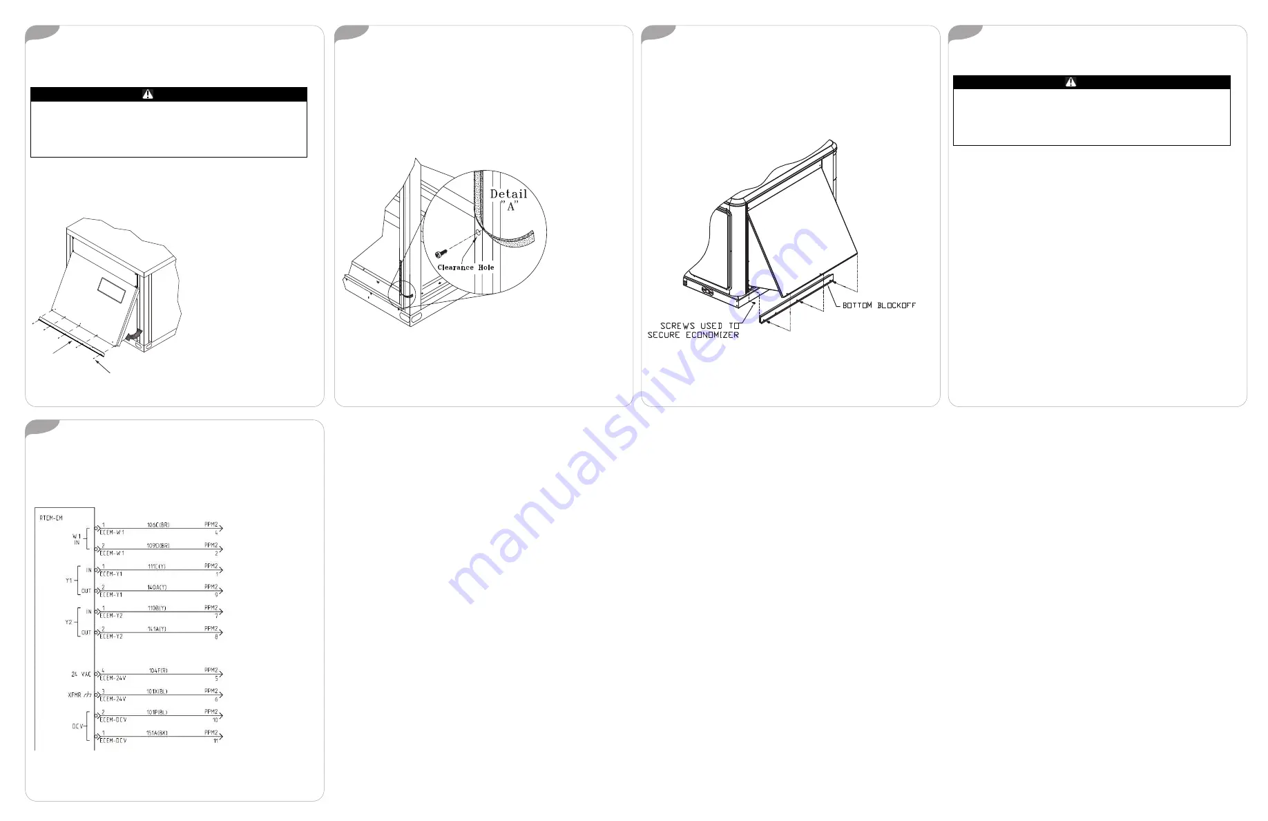
1. Remove filter access panel.
2. Remove the lower screws in the end panel. See
Figure 6
. Lay block off
angle aside for later installation.
Figure 6.
Remove lower screws
Remove screws and lay blockoff
angle aside.
Blockoff Angle
3. Do not remove the screws in the upper row of the end panel.
4. Grasp the bottom of the end panel and pull the economizer assembly
outward into the operating position. See
Figure 6
.
5. Remove approximately 3-inches of gasket material from the bottom of
each corner post to expose the holes used to attach the economizer
assembly to the unit. See
Figure 7
.
6. With the screws provided, secure each side of the economizer assembly
by inserting a screw through the clearance hole in the bottom of the
corner post and into the engagement hole in the economizer assembly.
Refer to
Figure 7
.
Figure 7.
Remove gasket material
7. Install the blockoff angle underneath the economizer. The blockoff angle
is designed to close the opening created, between the economizer and
the base, when the economizer assembly is in its operating position.
a. Holding the blockoff angle with the holes at the bottom and the
bottom angle outward, tilt the top forward and insert it into the
opening between the economizer and the unit base.
b. Press the bottom of the blockoff angle against the unit and line up
the holes. Using the provided screws, secure it into place.
Figure 8.
Blockoff installation
8. Proceed to
“Minimum Position Setting”
.
Minimum Position Setting
WARNING
Live Electrical Components!
Failure to follow all electrical safety precautions when exposed to live electrical
components could result in death or serious injury.
When it is necessary to work with live electrical components, have a qualified
licensed electrician or other individual who has been properly trained in
handling live electrical components perform these tasks.
To adjust the minimum position setting and check out the damper, the
power must be connected.
1. Close the unit disconnect and place the zone sensor fan selector in the
fan “ON” position and the heat/cool selector in the “OFF” position. This
will place the damper in the minimum ventilation position.
2. To adjust the minimum position setting for the required ventilation air,
turn the potentiometer (on the damper motor) clockwise to “open” (to
increase the amount of ventilation) or counterclockwise to “close” (to
decrease the amount of ventilation). The damper will open to this setting
each time the blower circuit is energized.
3. When adjusting minimum position, the damper may move to the new
setting in several small steps. Once the damper has remained in position
for 10 - 15 seconds without movement, it can be assumed it is at the new
position.
4. Replace the filter access panel. The damper will close when the blower
circuit is de-energized.
Wiring Connections
Locate unit wiring harness plug PPM2A. The plug is located in the upper left
section of the return air section. Remove the cap covering the plug, and
connect to the economizer wiring harness.
Figure 9.
Electromechanical wiring
ACC-SVN154D-EN 11 Sep 2021
Supersedes ACC-SVN154C-EN (Apr 2020)


