


HDWA-SVX001D-EN
31
The flange-adapter gasket must be placed with the
color-coded lip on the pipe and the other lip facing the
mating flange.
N
NO
OT
TIIC
CE
E
P
Piip
piin
ng
g C
Co
on
nn
ne
eccttiio
on
n L
Le
ea
akkss!!
F
Fa
aiillu
urre
e tto
o p
prro
ov
viid
de
e e
effffe
eccttiiv
ve
e sse
ea
all cco
ou
ulld
d rre
essu
ulltt iin
n
e
eq
qu
uiip
pm
me
en
ntt o
orr p
prro
op
pe
errtty
y--o
on
nlly
y d
da
am
ma
ag
ge
e..
T
To
o p
prro
ov
viid
de
e e
effffe
eccttiiv
ve
e sse
ea
all,, g
ga
asskke
ett cco
on
ntta
acctt ssu
urrffa
acce
ess
o
off a
ad
da
ap
ptte
err m
mu
usstt b
be
e ffrre
ee
e o
off g
go
ou
ug
ge
ess,, u
un
nd
du
ulla
attiio
on
nss o
orr
d
de
effo
orrm
miittiie
ess..
Victaulic Gasket Installation
1. Inspect supplied gasket to be certain it is suited for
intended service (code identifies gasket grade).
Apply a thin coat of silicone lubricant to gasket tips
and outside of gasket.
2. Install gasket, placing gasket over pipe end and
making sure gasket lip does not overhang pipe end.
Refer to the following figure for gasket
configuration.
3. Align and bring two pipe ends together and slide
gasket into position centered between the grooves
on each pipe. No portion of the gasket should
extend into the groove on either pipe.
4. Open fully and place hinged Victaulic
®
flange
around the grooved pipe end with the circular key
section locating into the groove.
5. Insert a standard hex head screw through the
mating holes of the Victaulic
®
flange to secure the
flange firmly in the groove.
6. Tighten fasteners alternately and equally until
housing screw pads are firmly together (metal-to-
metal); refer to
“Screw-Tightening Sequence for
Water Piping Connections,” p. 31
. Do NOT
excessively tighten fasteners.
N
No
otte
e:: Uneven tightening may cause the gasket to
pinch.
Figure 20.
Typical Victaulic
®
®
flange gasket
configuration
Table 10.
Installation data for 150 psig (1034.2 kPaG) flange adapters (Style 741)
Nominal Pipe Size
Assembly
Screw Size
(a)
Number of Assembly
Screws Required
Screw Pattern Diameter
Weight
in.
mm
in.
in.
mm
lb
kg
6
168.3
3/4 x 3-1/2
8
9.5
241
10.3
4.7
8
219.1
3/4 x 3-1/2
8
11.75
298
16.6
7.5
(a)
Screw size for conventional flange-to-flange connection. Longer screws are required when flange washer must be used. Grade 5 screws are
recommended.
Screw-Tightening Sequence for
Water Piping Connections
This section describes a screw-tightening sequence for
flanges with flat gaskets or O-rings. Remember that
improperly tightened flanges may leak.
N
No
otte
e:: Before tightening any of the screws, align the
flanges.
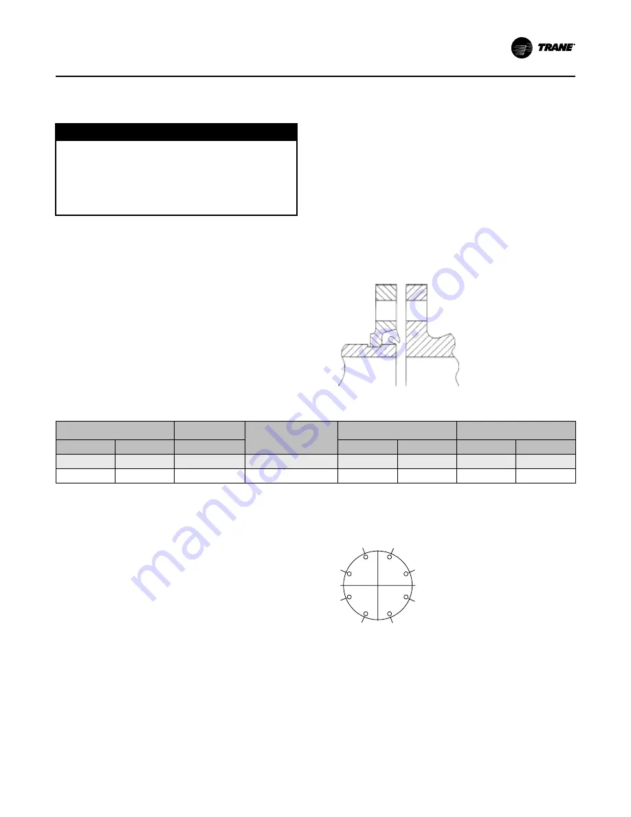
Flanges with 8 Screws
Tighten all screws to a snug tightness, following the
numerical sequence for the appropriate pattern as
shown in the following figure. Repeat this sequence to
apply the final torque to each screw.
Figure 21.
Flange screw tightening sequence (8
screws)
1
3
4
5
7
8
2
6
8 screws