background image

   11

Service Facts

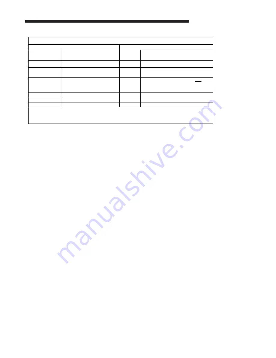
IGN Diagnostic Indicators Flash Codes

Steady OFF

Check Power or Failed Board 2 Flashes

System Lockout: Failed to detect or 

sustain flame

Slow Flash Rate Normal, No Call for Heat

3 Flashes Pressure switch problem detected

Fast Flash Rate Not used

4 Flashes

High Limit switch protection device 

open

Steady ON

Normal, No Call for Heat

5 Flashes

Flame sensed and gas valve not 

energized or flame sensed and no "W" 

signal

6 Flashes Flame Rollout Switch open

7 Flashes Thermostat miswired; W1 & W2 

Fast Flash Rate:

 The LED will flash on for 1/4 second, and off for 1/4 second

Slow Flash Rate:

 The LED will flash on for 3/4 second, then off for 1/4 second. 

The pause between groups of fast flashes is 3 seconds. 

Status LED

Liteport LED

IGN Diagnostic Indicators Flash Codes

Summary of Contents for 4YCY4036B-SF-1H

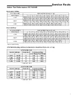
Page 1: ...p Rise Min Max F Orifice Qty Drill Size Natural Gas POWER CONN V PH HZ Min Brch Cir Ampacity Fuse Size Max amps Fuse Size Recmd amps COMPRESSOR Volts Ph Hz R L Amps L R Amps OUTDOOR COIL TYPE Rows F P...

Page 2: ...maintenance proceedures on the fan Operat ing the unit without the access panels properly installed may result in severe personal injury or death EXPLOSION HAZARD Propane gas is heavier than air and...

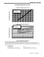
Page 3: ...TE INDOOR WET BULB 2 FIND INTERSECTION OF OD TEMP ID W B 3 READ LIQUID 4 OR SUCTION 5 PRESSURE IN LEFT COLUMN EXAMPLE 1 OUTDOOR TEMP 82 F 2 INDOOR WET BULB 67 F 3 AT INTERSECTION ACTUAL 4 LIQUID PRESS...

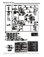
Page 4: ...4 Service Facts IMPORTANT Retain this wiring diagram please return this document to service information pack upon completion of work...

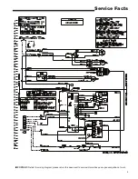
Page 5: ...5 Service Facts IMPORTANT Retain this wiring diagram please return this document to service information pack upon completion of work...

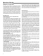
Page 6: ...ame as above 2nd stage heat has a 10 minute delay from the time of 1st stage ignition Comfort Control satisfied Safety Sequences Thisproductisequippedwithsafetydevicestoprotectagainst abnormal conditi...

Page 7: ...0 5 0 6 0 7 0 8 0 9 1 Watts 169 182 210 243 273 301 331 370 433 480 530 CFM 1025 1062 1068 1063 1060 1061 1064 1055 1015 975 990 Watts 225 253 283 315 348 381 414 449 484 522 575 CFM 1187 1201 1203 1...

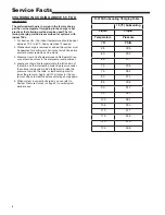
Page 8: ...uid Line Temperature and Refrigerant Pres sure at service valves in the compressor compartment 4 Locate your liquid line temperature in the left column of the table and the intersecting liquid line pr...

Page 9: ...9 Service Facts...

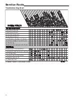
Page 10: ...High Suction Pressure Too Low Liquid Refrigerant floodback TXV System Liquid Refrig floodback Cap Tube System I D Coil Frosting Compressor Runs Inadequate or No Cooling Compressor O D fan Do Not Start...

Page 11: ...itch protection device open Steady ON Normal No Call for Heat 5 Flashes Flame sensed and gas valve not energized or flame sensed and no W signal 6 Flashes Flame Rollout Switch open 7 Flashes Thermosta...

Page 12: ...Trane 6200 Troup Highway Tyler TX 75707 01 13...

Reviews: