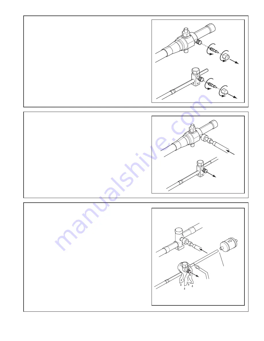
Trane 4TTR4018L Installer'S Manual Download Page 9

18-AC51D1-8-EN 


    9 

STEP 2

 - Remove the pressure tap cap and 

valve cores from both service valves. 

STEP 3

 - Purge the refrigerant lines and indoor 

coil with dry nitrogen.

STEP 4

 - Wrap a wet rag around the valve body 

to avoid heat damage and continue the dry nitro-
gen purge.

Braze the refrigerant lines to the service valves.

For units shipped with a field-installed external 
drier, check liquid line filter drier’s directional flow 
arrow to confirm correct direction of refrigeration 
flow (away from outdoor unit and toward evapo-
rator coil) as illustrated. Braze the filter drier to 
the Liquid Line. 

Continue the dry nitrogen purge. Do not remove 
the wet rag until all brazing is completed.

Important: Remove the wet rag before stopping 
the dry nitrogen purge.

Note:

 Install drier in Liquid Line.

3-4” from valve

Summary of Contents for 4TTR4018L

Page 1: ...approved matched indoor and outdoor systems All of the manufacture s split systems are A H R I rated only with TXV EEV indoor systems Some of the benefits of installing approved matched indoor and ou...

Page 2: ...m for component replacement For specific handling concerns with R 410A and POE oil reference Retrofit Bulletins SS APG006 EN and APP APG011 EN Extreme caution should be exercised when opening the Liqu...

Page 3: ...imits 1 The maximum length of refrigerant lines from outdoor to indoor unit should NOT exceed sixty 60 feet 2 The maximum vertical change should not exceed sixty 60 feet 3 Service valve connection dia...

Page 4: ...n 12 to Shrubbery Min 12 to Wall Position the outdoor unit a minimum of 12 from any wall or surrounding shrubbery to ensure adequate airflow Outdoor unit location must be far enough away from any stru...

Page 5: ...ction 4 Setting the Unit 4 1 Pad Installation When installing the unit on a support pad such as a concrete slab consider the following The pad should be at least 1 larger than the unit on all sides Th...

Page 6: ...erant Line Insulation Important The Vapor Line must always be insulated DO NOT allow the Liquid Line and Vapor Line to come in direct metal to metal contact Vapor Line Liquid Line Insulation Determine...

Page 7: ...g structure due to vibration transmission from the refrigerant lines For Example When the refrigerant lines have to be fastened to floor joists or other framing in a structure use isolation type hange...

Page 8: ...or other appropriate method every 8 ft 8 Feet Maximum Isolation Through Wall DO NOT hang line sets from ductwork Sealant Insulation Vapor Line Wall Ductwork Isolator Line Set Section 7 Refrigerant Li...

Page 9: ...the service valves For units shipped with a field installed external drier check liquid line filter drier s directional flow arrow to confirm correct direction of refrigeration flow away from outdoor...

Page 10: ...2 Check for leaks by using a soapy solu tion or bubbles at each brazed location Remove nitrogren pressure and repair any leaks before continuing Section 8 Refrigerant Line Leak Check 8 1 Check For Le...

Page 11: ...te blank off the vacuum pump and micron gauge and close the valves on the manifold gauge set 1 MIN Section 10 Service Valves 10 1 Open the Gas Service Valve 0350 Microns ON OFF CAP 1 4 TURN ONLY COUNT...

Page 12: ...ve System Service Port 3 16 Hex Wrench Unit Side of Service Valve Extreme caution should be exercised when opening the Liquid Line Service Valve Turn counterclockwise until the valve stem just touches...

Page 13: ...l low voltage wires behind the service valve cover as shown Red Yellow Green White Blue W1 B G Y1 R W1 W2 G B O BK Y R Yellow Yellow Blue Blue Black W2 YLO Variable Speed Furnace Hook up Diagram W2 Pi...

Page 14: ...G Y2 B O BK D Y1 R Neatly bundle all low voltage wires behind the service valve cover as shown Yellow Yellow Blue Blue Yellow Yellow Blue Blue Notes 1 See User Interface setup menu for cooling CFM opt...

Page 15: ...2 R to O jumper must be in place as shown for cooling only non heat pump systems for proper operation 3 Yi and Yo connections must be made as shown for freeze protection and internally mounted con de...

Page 16: ...h Voltage Ground Ground the outdoor unit per national state and local code requirements LIVE ELECTRICAL COMPONENTS During installation testing servicing and troubleshooting of this product it may be n...

Page 17: ...s to apply power to the indoor and outdoor units STEP 5 Set system thermostat to ON OFF DONE CANCEL ON OFF STEP 4 Wait one 1 hour before starting the unit if compressor crankcase heater acces sory is...

Page 18: ...rtant to return in the spring or summer to accurately charge the system in the cooling mode when outdoor ambient tempera ture is above 55 F STEP 1 Use the refrigerant line total length and lift measur...

Page 19: ...0 Add 2 of Subcooling Add 4 of Subcooling Add 6 of Subcooling Use Design Subcool Value 60 50 40 30 25 20 15 10 0 3 Ton Units SUBCOOL CHARGING CHART CORRECTIONS TABLE FOR LINE LENGTH AND RISE TOTAL REF...

Page 20: ...ssure should be ap proximately 327 PSI This is the shown as the intersection of the Final Subcooling column and the Liquid Temperature row Table 14 2 8 9 10 11 12 13 14 179 182 185 188 191 195 198 195...

Page 21: ...4TTX5049E1 4TXCD010CC3 Cooling 1400 CFM LIQUID PRESSURE PSIG OUTDOOR TEMPERATURE Degree F SUCTION PRESSURE PSIG OUTDOOR TEMPERATURE Degree F COOLING PERFORMANCE CAN BE CHECKED WHEN THE OUTDOOR TEMP I...

Page 22: ...heckout Procedures and Troubleshooting 15 1 Operational And Checkout Procedures CHECKOUT PROCEDURE After installation has been completed it is recommended that the entire system be checked against the...

Page 23: ...C T O R C O I L L O W V O L T A G E F U S E S T U C K C O M P R E S S O R I N E F F I C I E N T C O M P R E F U N D E R C H A R G E R E F O V E R C H A R G E E X C E S S I V E E V A P L O A D N O N C...

Page 24: ...7 www trane com The manufacturer has a policy of continuous product and product data improvement and it reserves the right to change design and specifications without notice Representative only illust...

Reviews: