3270 3361 Rev 1
2
If several sensors must share one transformer, the
phase (~) must always be connected to the 24V
connector in each sensor to maintain polarity and to
avoid short-circuit through the shared common line
at the controller (Figure 3).
Figure 3:
One ac power supply for several sensors
Figure 4 shows how to wire the sensor with 24 Vac
power from a unit controller.
Figure 4:
Power supply from controller
Mounting the sensor
1.
Select a proper location in the room to mount the
CO
2
sensor. Look for an interior wall with good
air circulation, approximately 54 in. (1.4 m) from
the floor.
2.
Remove the back plate from the sensor and
thread the power wires and output signal wire
through the hole in the back plate (Figure 1 on
page 1). For surface wiring, make cut-outs with
pliers to the thinner section of the upper or lower
edge of the back plate and to thread the wires
through.
3.
Mount the back plate to the wall with screws.
Note that the arrow on the back plate shows the
mounting direction.
4.
On the circuit board, use the two jumpers next to
the terminal block to set up the type of output
(0–10 Vdc, 0–20 mA, 4–20 mA) (Figure 5). The
default setting is 4–20 mA.
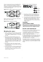
Figure 5:
Jumper settings for output type
5.
Insert the circuit board in the back plate as
shown in Figure 1 on page 1. Do not press the
metal tube while inserting the circuit board.
6.
Connect the power and signal wires to the screw
terminals of the circuit board. Figure 5 shows
the terminal locations. Refer to
Power supply
requirements
on page 1 for more information on
wiring ac power.
CAUTION
AVOID EQUIPMENT DAMAGE!
Make sure that you connect the power wire only to
the 24V terminal. Connecting the power wire to the
output terminal may result in equipment damage.
Service and maintenance
This CO
2
sensor has excellent stability and requires
no maintenance. In most environments the
recommended calibration interval is five years. A
trained service technician can use a portable CO
2
meter to certify sensor calibration.
If, when checking the sensor, the reading differs too
much from the reference value, the sensor can be re-
calibrated in the field. A calibration kit, software,
and calibration gases are required.
If certified accuracy is required, the sensor must be
calibrated against accurate and traceable calibration
gases in a laboratory. Consult Trane BAS for further
details.


