18-BC53D1-2
7
Installer’s Guide
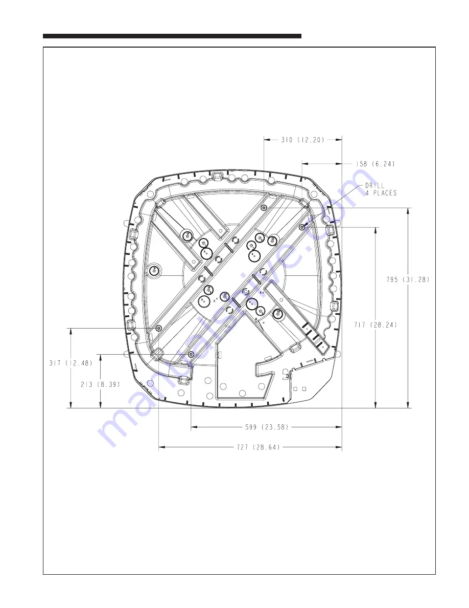
MOUNTING HOLE LOCATION
NOTE: ALL DIMENSIONS ARE IN MM (INCHES).
NOTE: For model base size,
see table on page 6.
From Dwg. 21D152637 Rev. 1
Page 1: ...istributor A GENERAL The following instructions cover 2TWZ9 Heat Pump Units NOTE These outdoor units must be used with indoor units equipped with Thermostatic Expansion Valve only Check for transporta...
Page 2: ...is the same Final refrigerant charge adjustment is necessary Use the Charging Charts in the outdoor unit Service Facts 1 Determine the most practical way to run the lines 2 Consider types of bends to...
Page 3: ...pressure taps NOTE Unnecessary switching of hoses can be avoided and com plete evacuation of all lines leading to sealed system can be accomplished with manifold center hose and connecting branch hos...
Page 4: ...rement is representative of the operating state and relative capacity of the heat pump system By measuring the change in delta T we can determine the need for defrost The coil sensor also serves to se...
Page 5: ...f this installation are the unit Operational and Checkout Procedures which are found in this instruction on page 8 To obtain proper performance all units must be operated and charge adjustments made i...
Page 6: ...46 37 1 4 870 34 1 4 7 8 3 8 152 6 98 3 7 8 219 8 5 8 86 3 3 8 933 36 3 4 2TWZ9036B 4 1267 49 7 8 946 37 1 4 870 34 1 4 7 8 3 8 152 6 98 3 7 8 219 8 5 8 86 3 3 8 933 36 3 4 2TWZ9048B 4 1267 49 7 8 946...
Page 7: ...18 BC53D1 2 7 Installer s Guide MOUNTING HOLE LOCATION NOTE ALL DIMENSIONS ARE IN MM INCHES NOTE For model base size see table on page 6 From Dwg 21D152637 Rev 1...
Page 8: ...Inadequate or No Cooling Htg ELECTRICAL Compressor O D Fan Won t Start Compressor Will Not Start But O D Fan Runs O D Fan Won t Start Compressor Hums But Won t Start Compressor Cycles on IOL I D Blow...