18-AC51D2-3
7
Installer’s Guide
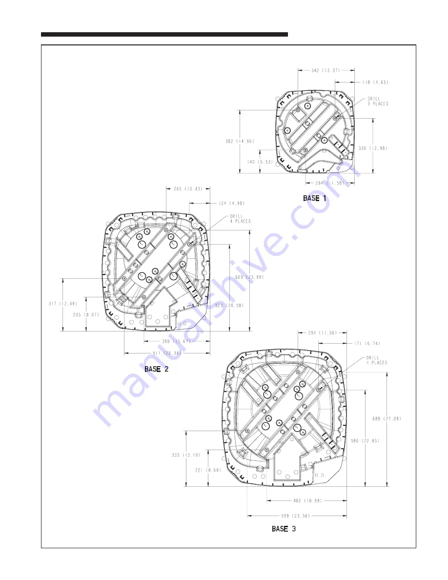
MOUNTING HOLE LOCATION
Note: All dimensions are in MM (Inches).
NOTE: For model base size,
see table on page 6.
From Dwg. 21D152637 Rev. 1
Page 1: ...move tabs by cutting with a sharp tool as shown in Figure 2 see page 2 2 The unit should be set on a level support pad at least as large as the unit base pan such as a concrete slab If this is not the...
Page 2: ...ant tubing INSIDE OR OUTSIDE THE STRUCTURE 4 Provide a pull thru hole of sufficient size to allow both liquid and gas lines 5 Be sure the tubing is of sufficient length 6 Uncoil the tubing do not kin...
Page 3: ...oap bubbles or other leak checking methods to see that all field joints are leak free If not release pressure then repair SYSTEM EVACUATION NOTE Since the outdoor unit has a refrigerant charge the gas...
Page 4: ...r by closing the system main disconnect switch This will activate the compressor sump heat where used Do not change the Thermostat System Switch until power has been applied for one 1 hour Following t...
Page 5: ...w voltage wiring to be No 18 AWG minimum conductor 4 ODT B must be set lower than ODT A 5 If outdoor thermostats ODT are not used connect W1 to W2 and W3 PRINTED FROM B152901 P02 PRINTED FROM B152908...
Page 6: ...8 210 8 1 4 57 2 1 4 457 18 2TTR1048A 2 2 730 28 3 4 724 28 1 2 651 25 5 8 1 1 8 3 8 137 5 3 8 65 2 5 8 210 8 1 4 57 2 1 4 457 18 2TTR1060A 3 1 933 36 3 4 829 32 5 8 756 29 3 4 1 1 8 3 8 143 5 5 8 92...
Page 7: ...18 AC51D2 3 7 Installer s Guide MOUNTING HOLE LOCATION Note All dimensions are in MM Inches NOTE For model base size see table on page 6 From Dwg 21D152637 Rev 1...
Page 8: ...ng 2 X X X X X 6 Inform owner on how to operate system and what to expect of it At the same time deliver Owner s Use and Care Booklet CHECKOUT PROCEDURE After installation has been completed it is rec...