


17
ST1-075A Ia 12/98
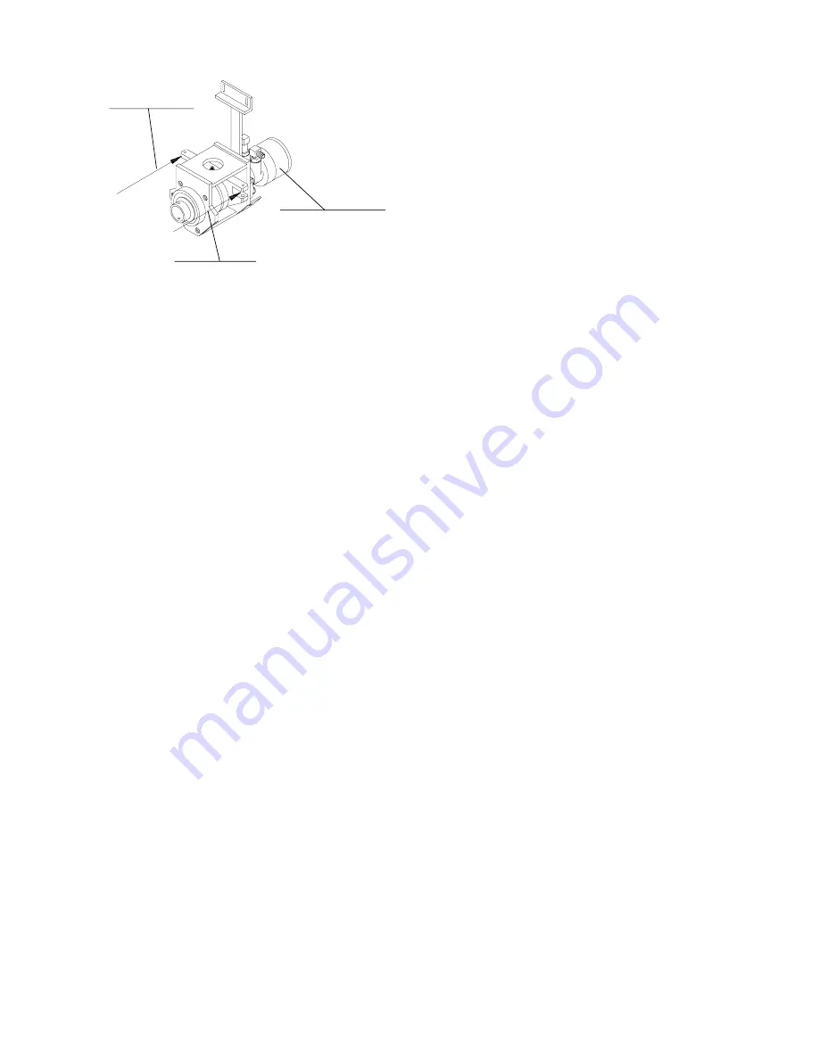
Figure 18
Drive Module Disassembly (Figure 19)
1.
Place drive module assembly in vice.
2.
Check shaker bearing assembly for end play
(Figure 19) before disassembling the drive
module assembly. Shaker bearing end play
can best be checked using the following
procedures.
•
Place dial indicator near center of shaker
drive plate (Figure 18).
•
While using back and forth hand force
against ends of shaker drive plate read dial
indicator.
NOTE: If dial indicator reading is more than .010
inch, bearing assembly should be disassembled
and bearings replaced with bearing kit. Refer to
drive module reassembly if old shaker bearings are
reused.
3.
Remove bolt (item 1) & grease fitting (item 11).
4.
Remove four bolts (item 10).
5.
Pull motor from assembly.
6.
With blunt one inch brass drift remove the
coupling block (item 3). The bearing (item 4)
and seal (item 2) will remain in the housing.
7.
Remove shaker bearing assembly from the
housing.
8.
Remove bearing and seal from housing (items
2 & 4).
9.
Remove push-pull joints by removing locking
bolts (item 13) & then drive out pins (item 12).
10. Remove shaker bearings (item 17) by
removing the lock nut (item 15), lock washer
(item 14) and nylos ring (item 16). A four inch
spanner wrench is required to remove lock nut
(item 15).
11. Inspect all components before
reassembly.
12. Motor seal kits are available with
disassembly/assembly instructions.
Drive Module Reassembly (Figure 19)
Reassemble in reverse order as noted in the
disassembly instructions. Care must be taken
regarding the following items.
1.
When old shaker bearings are reused surface
grind the spacer ring (item 9) equal to the end
play plus .002 inch determined at disassembly
(see step 2 in disassembly) e.g. for .005 inch
end play plus .002 for preload remove .007
inch from spacer with surface grinder. New
bearing sets are supplied with a new spacer
ring as a kit.
2.
Torque the lock nut (item 15) to 100-150 lb/ft.
Sockets are available for use with a torque
wrench. An adjustable spanner wrench with an
extension applying the force required relative
to wrench and extension length may also be
used, eg force (125 lbs) x length (1 ft) = 125 lb/
ft.
3.
Torque bolt (item 1) to 100 lb/ft.
4.
Torque six socket head capscrews (item 20) to
100 lb/ft.
5.
After torquing six socket head capscrews,
install shim stacks which were removed (item
21).
NOTE: Shim stack must fill complete space
between modular housing and frame to within .010
inch before tightening through bolts and nuts (item
22 & 26) to 40 lb-ft.
6.
The flow control valve is normally set at
adjustment point 6 for proper operating sped
(Figure 14, item 7).
7.
Auger speed of 240 to 260 rpm must be
checked with sandbagger on host vehicle.
Higher number on flow control increases speed
and lower number reduces speed.
OM0210
Shaking Direction
Set dial indicator in this
area to check shaker
bearing end play
Shaking Direction


