Trailer Vision DR-400N Instruction Manual Download Page 4

4

Do not place near of air bag effective range.

-  It may cause malfunction of air bag or accident, injury due to hitting monitor by air bag.

Keep clean dust on power socket.

- It may cause electronic shock and fire by bad connection.

Do not put a pin or needle on the hole or crack in the body.

-  In case of inserting them, stop to operate, it may cause electronic shock, fire and malfunction.

Do not use in problem condition as like smoking, smell something burn.


- It may cause fire. Stop to use and make inquiries to agency.

Should install while power off. (After install products, connect DC jack)

- It may cause to electronic shock or malfunction.

Do not operate the product while driving.

- It may cause an accident. Stop in a safe place and operate.

Do not put the product in place where sudden temperature increasing and should use on optimum 
voltage, temperature and humidity.

 - It may cause to electronic shock or malfunction.

Do not pull cord with a jerk, should catch a plug and pull. Do not use damaged cord.

- It may cause cord malfunction, electronic shock and fire.

Do not clean exterior with alcohol, volatility or oily solvent. Neither keep touching rubber and plastic 
for long time. 

- It may cause change of surface, fall of paint, malfunction and fire.

Please use the USB cable at 2 USB ports together when checking the data.  

- If only one USB port is used, the power may not be supplied well and the hard disk could not be read. 

Please do not install the product where has lots of vibration or not fixed securely.

 - It may cause traffic 

accident and injury due to an interruption from detaching the product by vibration during driving.

Please avoid wiring of connected codes from high fever.

- It may cause electric shock and fire from melting of covering for codes.

WARNING

Please confirm the caution according to a kind of vehicle if the vehicle has an air bag.

-  It may cause malfunction of air bag if it installed and wired at the wrong place.

Please prevent the loss of power during update. 
If the power is lost during update, the product may not be working.

Summary of Contents for DR-400N

Page 1: ...DRIVING VIDEO RECORDER Design and Specifications are subject to change without notice PRINTED IN KOREA ver 1 0 Thank you for purchasing this product For correct usages and application please read this...

Page 2: ...COMPONENTS PARTS INSTALL IN YOUR CAR PRODUCT OPERATION Power ON OFF FIRM WARE UPDATE Event Recording Abnormal Operation Check LED Description PC VIEWER MANAGER Installation Execution of PC VIEWER MAN...

Page 3: ...guarantee the fault and some repair costs will be demanded Please check for seamless use whether the product is working well or not at least once per month Please send the product to manufacturer if t...

Page 4: ...pull cord with a jerk should catch a plug and pull Do not use damaged cord It may cause cord malfunction electronic shock and fire Do not clean exterior with alcohol volatility or oily solvent Neither...

Page 5: ...is not fixed properly Afterwiringforthecodes pleasemoveittothelocationwhereisnotinterruptedofdrivingandcoilthe codes with friction tape and fix it by clamp It may cause electric shock or fire as the c...

Page 6: ...ody and parts mentioned below are not included when you purchase this prod uct contact the shop where you purchased the product The shape of each component may be changed without notice for the better...

Page 7: ...rding LED 3 Remote Controller Sensor 4 Hard Case 5 CASE LOCK 6 MEMORY LOCK 7 TRIGGER 8 MIC GPS REMOTE CONTROLLER 9 POWER CABLE 1 EMERGENCY RECORDING About 30seconds Recording 2 Video Switch of Cam 1 2...

Page 8: ...n and install the product with the ignition key removed Do not use any other cables only use the supplied cables If the vehicle has a tinted or heated screen the GPS receiver rate may be poor an exter...

Page 9: ...g route speed time direction and location information is also recorded Recommended position of Installation Install with the GPS logo facing upwards T i n t i n g s e c t i o n G P S a n t e n n a Pos...

Page 10: ...d the recording ratio is about 3 1 of the capacity i e 3 parts Normal to 1 part Event Manual 1 This product has no separate power button the unit is powered via ignition a timer for igntion off record...

Page 11: ...econds after an event accident occurs 30 seconds in total 5 min 4min 30sec For example if an event happens 9 minutes and 40 seconds after starting recording 10 sec 20 sec 5 min 5 min 5 min Event Save...

Page 12: ...ng LIGHT ON LIGHT ON LIGHT ON LIGHT ON LIGHT ON LIGHT ON LIGHT ON LIGHT ON LIGHT ON LIGHT ON AFTER 15SECONDS Flashing 1 second interval Flashing 1 second interval Flashing Quickly Flashing Quickly Lig...

Page 13: ...stalled Put the enclosed CD in your PC double click the setup exe file and complete the following installation When the PC viewer installation is completed an icon will be created on PC screen Please...

Page 14: ...relative to the monitor screen size Ends the program Open recorded data memory tray Searches the file list by date and time Map information Display driving route on the map Displays GPS information at...

Page 15: ...tion O Disconnection X Displays the recording status NORMAL EVENT Displays the Firmware version Connection of Mic M No connection of Mic X Recording with Standard quality N Recording with High Definit...

Page 16: ...16 How to play video 2 Please click file reading Please select memory and click confirm 1 Please open the software on the PC...

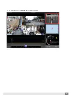
Page 17: ...17 3 Please double click the file for playing video...

Page 18: ...ing menu will be shown Changing the playback screen Playback screen changes as left and right Screen ratio Control recording data screen s ratio Video It turns around upside and downside I turns aroun...

Page 19: ...High Definition Standard Set G sensor Sensitivity 5steps 1 Low 5 High If speed goes beyond the setting speed the file saves as event file Sets the time press sync button to set the present time from t...

Page 20: ...20 Timeset cfg file will be created after checking time setting and saving the value This means time setting is correctly set Please check this status be fore device operation...

Page 21: ...ply Operating temperature Storage temperature Dimension W D H Weight 4 Channel input 1 Output 1 Input Full HD 1920 x 1080 or 960H 960 x 480 30fps normal Event G sensor H 264 AVI SSD Min 128GB max 1TB...

Page 22: ...please contact the service centre or store that you purchased A The key should be locked after inserting the memory tray If the recording LED is not operating please check or replace the power cable...

Page 23: ...23 MEMO...

Page 24: ...INSTRUCTION MANUAL...

Reviews: