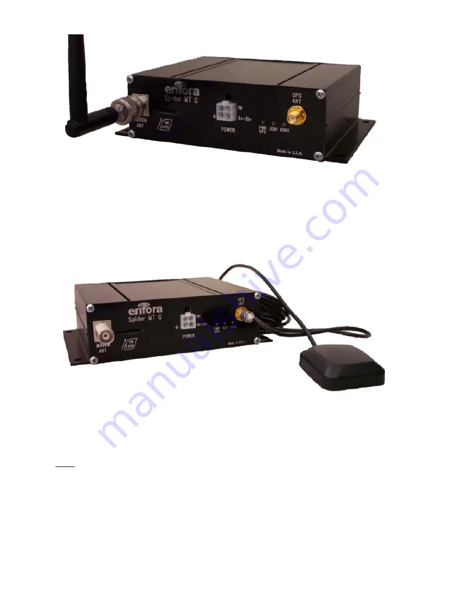
Figure 8 - GSM Antenna Connection
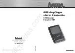
The GPS receiver inside the Spider MT-G powers the preamplifier in the GPS antenna (Active-style) by applying a
power of 3.3 Volts to the center conductor of the RF input to the GPS receiver. If a passive-style GPS antenna must
be used, please verify that it has a DC block installed in order to prevent shortening to ground. GPS antenna
connector on the Spider MT-G model is a SMA female connector. The GPS antenna must be placed in an area
where it can have direct view of the sky.
The GPS antenna must be connected to the connector labeled “GPS ANT”. See Figure 9 - GPS
Antenna Connection.
Figure 9 - GPS Antenna Connection
•
All cables should be installed in such a way that reduces cable stress
•
Do not cut, modify, tightly bend or fold the cables
•
Do not tightly roll the excess antenna cable
•
Do not connect the antenna cables with power supplied to the modem, damage may occur
Power
Proceed to install the power cable in the pre-determined location. Main power (red cable) should be routed to the
vehicle battery distribution point. Ignition sense power (white cable) should be routed to the vehicle ignition-switched
battery pickoff point in the vehicle fuse box. The ground wire (black cable) should be connected to a manufacturer
specified ground point.
Red
-
6-30V DC current (Fuse at 3A)
Black
- Common/Ground
White
-
Vehicle Ignition Sense (Fuse at 3A)
Summary of Contents for Enfora Spider MT-G
Page 5: ...2 Product Specifications...


