Rev1F
Coyote ST/AT/RT Hardware Installation Guide
Step A
Mounting the Unit
1.
Mount the Unit in a ventilated area out of the way of the driver’s
feet. (Note: the Unit is not weather proof).
2.
Be sure to mount the device where you can see the LED’s without
too much trouble in case technical support needs to know the status
of the LED’s.
3.
Choose how to mount the unit: (1) 3M VHB tape or (2) zip tie straps
which has been provided.
4.
The LABEL of the VLM should face towards the sky for the best
performance. Record the ESN off the GPS unit (white label)
Step B
Power Connection
1.
Ground: Connect the BLACK wire to chassis/vehicle ground.
Choose a good snug ground point that is not painted.
2.
Power: Connect the RED wire to a 12 volt constant supply. This
connection must be fused and capable of supplying 1 amp at
+12VDC.
3.
Ignition: Connect the WHITE wire to a 12 volt SWITCHED source.
This connection must be fused and capable of supplying 1 amp at
+12VDC when the vehicle is on and 0VDC when the ignition is off.
4. The best connections are the auxiliary power connections on the
fuse panel provided by some vehicle manufactures.
5. Connect and test all wires before connecting the power harness to
the unit.
6. Fuse connection kits may be needed
. (not supplied)
Step C
Installation Verification
1.
Go to
install.tyt1.net
. or Scan the QR Code below.
2.
Record the ESN/Serial number associated with the GPS unit.
3.
Record the Vehicle Identification Number (VIN)
4.
Park the vehicle outside with a clear view of the sky.
5.
Follow the prompts in the NetTrack Installer Check.
6.
If the verification fails, Check the LED’s on the GPS unit. And try again.
7.
You may also contact TYT_Support via our support site at
support.trackyourtruck.com
Track Your Truck, Inc.
Phone: 815-717-8482
Fax:877-376-5154
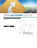
Coyote ST
Coyote AT
Coyote RT