background image

Installation / Preparation for commissioning


 TR-Electronic GmbH 2011, All Rights Reserved 

Printed in the Federal Republic of Germany 

Page 40 of 55 

TR - ECE - BA - DGB - 0084 - 05 

06/28/2017 

3.5 Analog – interface, basic functionalities 


3.5.1 Measuring system version with Analog-Voltage 

 
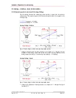
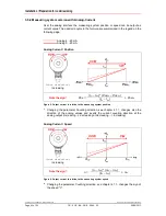
Over the analog interface the measuring system position or speed can be output as 
voltage value. The used acronyms in the formula are summarized in the legend on the 
following page. 


 Analog 0…+10 VDC 
 Analog -10…+10 VDC 


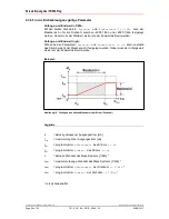
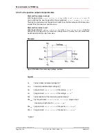
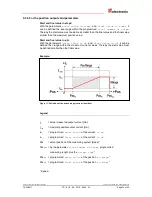
Analog Voltage / Position 


Count direction:


Increasing 

1)


Note the sign!


Pos = 

(U

O

 – U

SV

) * (Pos

FV

 – Pos

SV

+  Pos

SV


(U

FV

 – U

SV

Figure 2: Output voltage in relation to the measuring system position 


1)

  Changing the parameter Counting direction, see chapter 4.1.1, changes also the 

direction of the analog values and inverts the current counting direction at the 
analog output (increasing --> decreasing or decreasing --> increasing) 


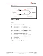
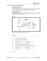
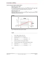
Analog Voltage / Speed 


Count direction:


Increasing 

2)


Note the sign!


n = 

(U

O

 – U

SV

) * (n

FV

 – n

SV

+  n

SV


(U

FV

 – U

SV

Figure 3: Output voltage in relation to the measuring system speed 


2)

  Changing the parameter Counting direction, see chapter 4.1.1, changes the sign of 

the speed "n". 


Summary of Contents for A**65 Series

Page 1: ...iebnahme _Konfiguration Parametrierung _Fehlerursachen und Abhilfen _Additional safety instructions _Installation _Commissioning _Configuration Parameterization _Cause of faults and remedies CEK 65 CO...

Page 2: ...ion bersetzung sowie die elektronische und fotografische Archivierung und Ver nderung bedarf der schriftlichen Genehmigung durch den Hersteller Zuwiderhandlungen verpflichten zu Schadenersatz nderungs...

Page 3: ...e Grundfunktionalit ten 12 3 5 1 Mess System Variante mit Analog Spannung 12 3 5 2 Mess System Variante mit Analog Strom 14 4 Parametrierung ber TRWinProg 16 4 1 Grundparameter 16 4 1 1 Z hlrichtung 1...

Page 4: ...84 05 06 28 2017 nderungs Index nderung Datum Index Erstausgabe 17 12 10 00 Erweiterung um COx 65 20 07 11 01 Hinweise f r den Einsatz in explosionsgef hrdeten Bereichen 07 06 13 02 A 70 erg nzt 20 03...

Page 5: ...Dokumentationen wie z B Produktdatenbl tter Ma zeichnungen Prospekte und der Montageanleitung etc dar Das Benutzerhandbuch kann kundenspezifisch im Lieferumfang enthalten sein oder kann auch separat a...

Page 6: ...067 optional Benutzerhandbuch 1 2 Verwendete Abk rzungen Begriffe CE_ Absolut Encoder mit optischer Abtastung 15 Bit Aufl sung Alle mechanischen Varianten CO_ Absolut Encoder mit optischer Abtastung 1...

Page 7: ...reten kann wenn die entsprechenden Vorsichtsma nahmen nicht getroffen werden bezeichnet wichtige Informationen bzw Merkmale und Anwendungstipps des verwendeten Produkts 2 2 Organisatorische Ma nahmen...

Page 8: ...e Verwendung sowie alle Informationen f r den gefahrlosen Einsatz des ATEX konformen Mess Systems in explosionsf higen Atmosph ren sind im Benutzerhandbuch enthalten Das in das Explosionsschutzgeh us...

Page 9: ...alog Versorgung min 0 5mm2 paarig verseilt und geschirmt Um eine hohe St rfestigkeit des Systems gegen elektromagnetische St rstrahlungen zu erzielen muss eine geschirmte Datenleitung verwendet werden...

Page 10: ...B der Preset einen Nullimpuls oder invertierte Signalfolgen bei einer Inkrementalschnitt stelle unterst tzt wird deshalb durch die ger tespezifische Steckerbelegung definiert Der Anschluss kann nur in...

Page 11: ...bel zwischen PC Adapter und PC Flachbandkabel 1 30 m Verbindungskabel zwischen PC Adapter und TR Schaltschrank Modul 15 pol SUB D Buchse Stecker Steckernetzteil 24 V DC 1A Versorgungsm glichkeit des a...

Page 12: ...10 VDC Analog 10 10 VDC Analog Spannung Position Z hlrichtung Steigend 1 Vorzeichen beachten Pos UA UAW PosEW PosAW PosAW UEW UAW Abbildung 2 Ausgangsspannung in Abh ngigkeit zur Mess System Ist Posit...

Page 13: ...Spannung in mV UEW programmierter Endwert der Spannung in mV Pos aktuelle Mess System Ist Position Schritte PosAW programmierter Anfangswert der Position in Schritten PosEW programmierter Endwert der...

Page 14: ...A Analog Strom Position Z hlrichtung Steigend 1 Vorzeichen beachten Pos IA IAW PosEW PosAW PosAW IEW IAW Abbildung 5 Ausgangsstrom in Abh ngigkeit zur Mess System Ist Position 1 Eine nderung des Param...

Page 15: ...s in A IEW programmierter Endwert des Stroms in A Pos aktuelle Mess System Ist Position Schritte PosAW programmierter Anfangswert der Position in Schritten PosEW programmierter Endwert der Position in...

Page 16: ...enz aus der Menge 20 21 22 212 1 2 4 4096 ist oder Sicherstellen dass sich Positionierungen im stromlosen Zustand bei einem Multi Turn Mess System innerhalb von 512 Umdrehungen befinden 4 1 Grundparam...

Page 17: ...en 1 Messl nge in Schritten Schritte pro Umdrehung Anzahl der Umdrehungen Zur Berechnung k nnen die Parameter Schritte Umdr und Anzahl Umdrehungen vom Typenschild des Mess Systems abgelesen werden 4 1...

Page 18: ...die programmierte gesamte Umdrehungsanzahl und ist somit vernachl ssigbar Vorgehensweise bei Linearachsen Vor und Zur ck Verfahrbewegungen Der Parameter Umdrehungen Nenner kann bei Linearachsen fest...

Page 19: ...e 4096 Schritte Umdr 148 3598633 Umdrehungen Anzahl mm Umdrehung 2000 mm 148 3598633 Umdr 13 48073499mm Umdr Bei 1 100mm Aufl sung entspricht dies einer Schrittzahl Umdrehung von 1348 073499 erforderl...

Page 20: ...chschaden durch einen Istwertsprung bei Ausf hrung der Preset Justage Funktion Die Preset Justage Funktion sollte nur im Mess System Stillstand ausgef hrt werden bzw muss der resultierende Istwertspru...

Page 21: ...ur vor bergehenden Zwischenspeicherung der Ausgangsdaten Auswahl Beschreibung Default nie Latch Funktion deaktiviert X 0 gelatcht Die Ausgangswerte sind eingefroren wenn am Latch Eingang low U 2 V anl...

Page 22: ...Parametern Anfangs und Endwertwert in mV kann innerhalb des Spannungsbereichs der Messbereich U festgelegt werden Dabei muss der Anfangswert kleiner als der Endwert definiert werden Beispiel Abbildun...

Page 23: ...iden Parametern Anfangs und Endwertwert in mV kann innerhalb des Spannungsbereichs der Messbereich U festgelegt werden Dabei muss der Anfangswert kleiner als der Endwert definiert werden Beispiel Abbi...

Page 24: ...chreibung Einheit Default Position Position wird als Stromwert ausgegeben Schritte X Geschwindigkeit Umdr Min Drehzahl wird als Stromwert ausgegeben 1 Min 4 3 2 Latch Der Parameter Latch dient zur vor...

Page 25: ...beiden Parametern Anfangs und Endwertwert in A kann innerhalb des Strombereichs der Messbereich I festgelegt werden Dabei muss der Anfangswert kleiner als der Endwert definiert werden Beispiel Abbildu...

Page 26: ...ndwert in A Mit den beiden Parametern Anfangs und Endwertwert in A kann innerhalb des Strombereichs der Messbereich I festgelegt werden Dabei muss der Anfangswert kleiner als der Endwert definiert wer...

Page 27: ...Messl nge in Schritten 4 4 2 Drehzahl 1 Min Im Onlinezustand wird im Feld 1 Min die aktuelle Mess System Drehzahl in min 1 angezeigt 5 Fehlerursachen und Abhilfen St rung Ursache Abhilfe Positionsspr...

Page 28: ...Fehlerursachen und Abhilfen TR Electronic GmbH 2011 All Rights Reserved Printed in the Federal Republic of Germany Page 28 of 55 TR ECE BA DGB 0084 05 06 28 2017...

Page 29: ...Printed in the Federal Republic of Germany TR Electronic GmbH 2011 All Rights Reserved 06 28 2017 TR ECE BA DGB 0084 05 Page 29 of 55 User Manual C__ 65 Analog...

Page 30: ...roduction translation as well as electronic and photographic archiving and modification require the written content of the manufacturer Violations shall be subject to claims for damages Subject to mod...

Page 31: ...suring system version with Analog Voltage 40 3 5 2 Measuring system version with Analog Current 42 4 Parameterization via TRWinProg 44 4 1 Basic parameters 44 4 1 1 Count direction 44 4 1 2 Scaling pa...

Page 32: ...5 TR ECE BA DGB 0084 05 06 28 2017 Revision index Revision Date Index First release 12 17 10 00 COx 65 supplemented 07 20 11 01 Notes for use in explosive atmospheres 06 07 13 02 A 70 added 03 20 15 0...

Page 33: ...s dimensional drawings leaflets and the assembly instructions etc The User Manual may be included in the customer s specific delivery package or it may be requested separately 1 1 Applicability This U...

Page 34: ...the User Manual 1 2 Abbreviations used Terminology CE_ Absolute Encoder with optical scanning unit 15 bit resolution all mechanical versions CO_ Absolute Encoder with optical scanning unit 15 bit res...

Page 35: ...red precautions are not met indicates important information or features and application tips for the product used 2 2 Organizational measures This User Manual must always kept accessible at the site o...

Page 36: ...fe usage of the ATEX compliant measuring system in explosive atmospheres are contained in the User Manual Standard measuring systems that are installed in the explosion protection enclosure can theref...

Page 37: ...shielded Analog Analog Supply voltage min 0 5mm2 twisted in pairs and shielded A shielded data cable must be used to achieve high electromagnetic interference stability The shielding should be connec...

Page 38: ...ernal inputs such as the Preset a reference pulse or inverted signal sequences in case of an incremental interface is therefore defined by the device specific pin assignment The connection can be made...

Page 39: ...ion cable between PC adapter and PC Flat ribbon cable 1 30 m Connection cable between PC adapter and TR switch cabinet module 15 pol SUB D female male Plug Power Supply Unit 24 V DC 1A The connected d...

Page 40: ...C Analog 10 10 VDC Analog Voltage Position Count direction Increasing 1 Note the sign Pos UO USV PosFV PosSV PosSV UFV USV Figure 2 Output voltage in relation to the measuring system position 1 Changi...

Page 41: ...of the voltage in mV UFV programmed final value of the voltage in mV Pos actual position of the measuring system steps PosSV programmed start value of the position in steps PosFV programmed final val...

Page 42: ...alog Current Position Count direction Increasing Note the sign Pos IO ISV PosFV PosSV PosSV IFV ISV Figure 5 Output current in relation to the measuring system position 1 Changing the parameter Counti...

Page 43: ...f the current in A IFV programmed final value of the current in A Pos actual position of the measuring system steps PosSV programmed start value of the position in steps PosFV programmed final value o...

Page 44: ...xponent of 2 of the group 20 21 22 212 1 2 4 4096 or Ensure that every positioning in the de energized state for a multi turn measuring system is within 512 revolutions 4 1 Basic parameters 4 1 1 Coun...

Page 45: ...revolution Number of revolutions To calculate the parameters Number of steps per revolution and the Number of revolutions can be read on the measuring system nameplate 4 1 2 2 Revolutions numerator Re...

Page 46: ...d is therefore negligible Preferably for linear axes forward and backward motions The parameter Revolutions denominator can be programmed as a fixed value of 1 The parameter Revolutions numerator is p...

Page 47: ...148 3598633 revolutions Number of mm revolution 2000 mm 148 3598633 revs 13 48073499mm rev For 1 100mm resolution this equates to a Number of steps per revolution of 1348 073499 Required programming...

Page 48: ...property by an actual value jump when the Preset adjustment function is performed The preset adjustment function should only be performed when the measuring system is at rest otherwise the resulting...

Page 49: ...represents the speed 1 Min 4 2 2 Latch The parameter Latch is for the transient saving of the output data Selection Description Default Never Latch function disabled X 0 Locked output data are frozen...

Page 50: ...and final value in mV With the parameters start value in mV and final value in mV it can be defined the U range within the maximum voltage values Thereby the start value must be defined smaller than...

Page 51: ...mV With the parameters start value in mV and final value in mV it can be defined the U range within the maximum voltage values Thereby the start value must be defined smaller than the final value Exa...

Page 52: ...speed the type of analog output is defined Selection Description Unit Default Position current value represents the position Steps X Speed 1 Min current value represents the speed 1 Min 4 3 2 Latch Th...

Page 53: ...ue in A With the parameters start value in A and final value in A it can be defined the I range within the maximum current values Thereby the start value must be defined smaller than the final value E...

Page 54: ...nd final value in A With the parameters start value in A and final value in A it can be defined the I range within the maximum current values Thereby the start value must be defined smaller than the f...

Page 55: ...osition value programmed Total number of steps 4 4 2 Speed 1 Min In the online state in the field Speed 1 Min the current measuring system speed in min 1 is displayed 5 Causes of faults and remedies F...

Reviews: