


User's Manual l MBa8x UM 0100 l © 2021, TQ-Systems GmbH
Page 35
TQMa8x
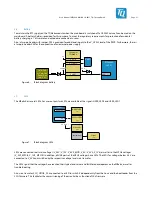
USB 2.0 OTG
OTG1
DN/P
ESD
(824014)
DN/P
Switch
MIC2026
V_5V_USB
VBUS_OTG1
ESD
(824014)
VBUS_OTG1
OTG1_VBUS
VBUS_OTG1
Figure 22: Block diagram USB OTG
The processor supports USB 2.0 with Hi-Speed, Full-Speed and Low-Speed. Depending on the software and hardware used, the
effective read and write rates of the ports may vary.
Table 23: Properties of USB-OTG
Parameter
Min.
Typ.
Max. Unit
Note
Voltage
4,75
5
5,25
V
-
Current
500
1000
1250
mA
-
Voltage dip at load
-
-92
-
mV
With a load of 500 mA
Read rate
-
20,1
-
MB/s
-
Write rate
-
8,8
-
MB/s
-
3.14.17
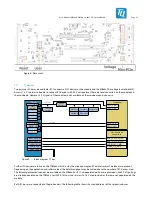
SD card
The SD card connector is directly connected to the SDHC controller of the TQMa8x module via a 4-bit wide data interface.
The SDHC controller in the TQMa8x basically supports UHS-I SD cards in transfer mode SDR104 according to the SD card
standard 3.0. This allows transfer rates of up to 104 Mbyte/s.
The SD card is permanently supplied with 3.3 V, the pull-ups are also connected to this voltage. The signals SW1_WP and
SD1_CD# have a fixed I/O voltage of 1.8 V. Their 10 kΩ pull-ups are therefore connected to 1.8 V.
It is possible to boot from SD card (see chapter 3.5). All data lines are provided with ESD protection.
TQMa8x
SD-Card
Slot (X42)
USDHC 1_CLK
USDHC1_CMD
USDHC1_DATA [3:0]
USDHC1_CD#
USDHC1_RESET#
Pin header X62
& load switch
Figure 23:
Block diagram SD card
Note: SD card initialisation after reset
A load switch is placed on the mainboard to reinitialize the SD card in the event of a system reset from
the host. This is controlled with the signal USDHC1_RESET# (multiplexed as GPIO4_IO07) and is
available at pin header X62.


