TPS 121122 Handbook Download Page 17


Page 16 

8. Warranty 

TPS Pty. Ltd. guarantees all instruments and sensors to be free from defects in 
material and workmanship when subjected to normal use and service. This 
guarantee is expressly limited to the servicing and/or adjustment of an instrument 
returned to the Factory, or Authorised Service Station, freight prepaid, within 
twelve (12) months from the date of delivery, and to the repairing, replacing, or 
adjusting of parts which upon inspection are found to be defective. Warranty 
period on sensors is three (3) months. 

There are no express or implied warranties which extend beyond the face hereof, 
and TPS Pty. Ltd. is not liable for any incidental or consequential damages 
arising from the use or misuse of this equipment, or from interpretation of 
information derived from the equipment. 

Shipping damage is not covered by this warranty. 

PLEASE NOTE: 

A guarantee card is packed with the instrument or sensor. This card must be 
completed at the time of purchase and the registration section returned to TPS 
Pty. Ltd. within 7 days. No claims will be recognised without the original 
guarantee card or other proof of purchase. This warranty becomes invalid if 
modifications or repairs are attempted by unauthorised persons, or the serial 
number is missing. 

PROCEDURE FOR SERVICE 

If you feel that this equipment is in need of repair, please re-read the manual. 
Sometimes, instruments are received for "repair" in perfect working order. This 
can occur where batteries simply require replacement or re-charging, or where 
the sensor simply requires cleaning or replacement. 

TPS Pty. Ltd. has a fine reputation for prompt and efficient service. In just a few 
days, our factory service engineers and technicians will examine and repair your 
equipment to your full satisfaction. 

To obtain this service, please follow this procedure: 
Return the instrument AND ALL SENSORS to TPS freight pre-paid and insured 
in its original packing or suitable equivalent. INSIST on a proof of delivery 
receipt from the carrier for your protection in the case of shipping claims for 
transit loss or damage. It is your responsibility as the sender to ensure that TPS 
receives the unit. 

Summary of Contents for 121122

Page 1: ...ction has a diagram and explanation of the display and controls of the pH Cube It also contains a full listing of all of the items that you should have received with your pH Cube Please take the time to read this section as it explains some of items that are mentioned in subsequent sections 3 Main Section The main section of the handbook provides complete details of the pH Cube including operating...

Page 2: ...tion Notes 7 4 mV Calibration 7 5 Temperature Calibration 8 5 1 Calibration Procedure 8 5 2 Calibration Notes 8 5 3 Manual Temperature Setting 8 6 Troubleshooting 9 6 1 pH and mV Troubleshooting 9 6 2 Temperature Troubleshooting 10 7 Appendices 11 7 1 pH Buffer Values Vs Temperature 11 7 2 pH Sensor Fundamentals 12 7 3 Checking the reference junction of a pH sensor 14 7 4 Determining if an instrum...

Page 3: ...Control Used for pH asymmetry calibration in pH6 88 or pH7 00 buffer See section 3 Slope Control Used for pH slope calibration in a buffer that is at least 2 to 3 pH away from pH7 00 eg pH4 00 pH9 23 or pH10 00 See section 3 Manual Temp Control Used to manually set the temperature of the solution for pH temperature compensation Only active when temperature sensor is unplugged See section 5 3 ...

Page 4: ...connected to the pH mV Connector Temp Connector Used to connect Temperature sensor This sensor provides temperature readout as well as Automatic Temperature Compensation for pH readings Temp Cal Control Used for temperature calibration See section 5 12V DC Power Connector Used to connect 12V AC DC Adaptor The pH Cube can run off any 12V DC source with at least 200mA output The 12V DC connector has...

Page 5: ...ensor 7 AC DC Power Adaptor 130044 8 pH Cube Handbook 130050 1 4 Specifications Ranges Resolution Accuracy pH 0 to 14 00 pH 0 01 pH 0 01 pH mV 0 to 1999 mV 1 mV 1 mV Temperature 10 0 to 120 0 O C 0 1 O C 0 2 O C Input Impedance 3 x 10¹² Ω Asymmetry Range Approx 1 00 to 1 00 pH Slope Range Approx 85 0 to 105 0 Temperature Compensation Automatic 0 to 100 0 o C Manual 5 to 100 o C Power 12V DC by AC ...

Page 6: ... 2 Operating Modes Switch the function switch to any one of the following three operating modes Note the mode enunciator P for pH E for EMF mV and C for O C Function Switch Position Display example pH mV Temp ...

Page 7: ...ready been calibrated or manually set see sections 5 1 and 5 3 4 Remove the wetting cap from the pH sensor 5 Rinse the pH and Temperature sensors in distilled water and blot them dry 6 Place both sensors into a small sample of primary buffer that is at or near pH7 eg pH6 88 or pH7 00 The bulb and reference junction should both be covered as per the diagram below DO NOT place the sensors directly i...

Page 8: ...er use When the reading has stabilised adjust the Slope control until the display shows the value of the buffer at the current temperature For TPS buffers this is shown on the bottle Refer also to the table in section 7 1 10 The pH Cube is now calibrated and is ready for use Discard the used samples of buffer 3 2 Calibration Notes 1 A 1 point calibration using the Calibrate control in a pH6 88 or ...

Page 9: ...ker 4 When the reading has stabilised adjust the Temp Cal control until the display shows the same temperature as the mercury thermometer 5 The Temperature function of the pH Cube is now calibrated and is ready for use 5 2 Calibration Notes 1 Temperature does not need to be recalibrated unless the Temperature sensor is replaced 5 3 Manual Temperature Setting Manual temperature setting is only avai...

Page 10: ...nsor Slope calibration with Slope control in low or high buffer fails Slope is less than 85 0 1 Glass bulb not clean 2 Sensor is aged 3 Connector is damp 4 Buffers are inaccurate Clean glass bulb as per instructions supplied with the sensor Attempt rejuvenation as per instructions supplied with the sensor If not successful replace sensor Dry in a warm place Replace buffers Inaccurate readings even...

Page 11: ...er until dissolved 6 2 Temperature Troubleshooting Symptom Possible Causes Remedy Meter reads 1 in Temperature mode Temperature sensor is connected but is faulty Check the temperature sensor connector and replace if necessary Replace temperature sensor part no 121245 if problem persists Temperature readings do not vary and Manual Temp control is active when temperature sensor is plugged in 1 Fault...

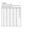
Page 12: ...9 46 10 32 5 4 00 6 95 7 09 9 40 10 25 10 4 00 6 92 7 06 9 33 10 18 15 4 00 6 90 7 04 9 28 10 12 20 4 00 6 88 7 02 9 23 10 06 25 4 01 6 87 7 00 9 18 10 01 30 4 01 6 85 6 99 9 14 9 97 35 4 02 6 84 6 98 9 10 9 93 40 4 03 6 84 6 97 9 07 9 90 45 4 04 6 83 6 97 9 04 9 89 50 4 05 6 83 6 97 9 01 9 83 55 4 06 6 83 6 97 8 99 60 4 08 6 84 6 97 8 96 65 4 10 6 84 6 97 8 94 70 4 12 6 85 6 97 8 92 75 4 14 6 85 ...

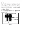
Page 13: ...unction A saturated solution of KCl is used to make contact with the sample It is vital that the KCl solution has an adequate flow rate in order to obtain stable accurate pH measurements 7 2 1 Asymmetry of a pH Sensor An ideal pH sensor produces 0 mV output at 7 00 pH In practice pH sensors generally produce 0 mV output at slightly above or below 7 00 pH The amount of variance from 7 00 pH is call...

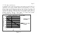
Page 14: ...practice pH sensors usually produce slightly less than this The output of a pH sensor is expressed as a percentage of an ideal sensor For example an ideal sensor that produces 59mV pH unit has 100 Slope An sensor that produces 50 15mV pH unit has 85 Slope see Figure 7 2 600 400 200 0 200 400 600 0 7 14 85 Slope at 25 oC 50 15mV pH 100 Slope at 25 oC 59mV pH Response of pH Electrode as a Function o...

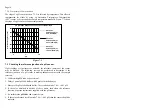
Page 15: ...gure 7 3 7 3 Checking the reference junction of a pH sensor If pH readings are inaccurate or unstable the reference junction of the sensor may be blocked The following test can be performed to determine if the reference junction of a pH sensor is making adequate contact with the sample solution 1 Calibrate the pH Cube as per section 3 2 Dilute 1 part of pH6 88 buffer with 9 parts of distilled wate...

Page 16: ... piece of wire or a paper clip etc 4 If the pH Cube is operating correctly the reading should be totally stable at around pH7 00 with the wire firmly in place If not the meter requires servicing 5 Now carefully disconnect the wire from the centre pin only make sure the other end of the wire remains connected to the outside frame of the connector 6 The reading should steadily drift away from 7 00 e...

Page 17: ...registration section returned to TPS Pty Ltd within 7 days No claims will be recognised without the original guarantee card or other proof of purchase This warranty becomes invalid if modifications or repairs are attempted by unauthorised persons or the serial number is missing PROCEDURE FOR SERVICE If you feel that this equipment is in need of repair please re read the manual Sometimes instrument...

Page 18: ...ired and returned to you by air express where possible For out of warranty units a repair cost will be calculated from parts and labour costs If payment is not received for the additional charges within 30 days or if you decline to have the equipment repaired the complete unit will be returned to you freight paid not repaired For full account customers the repair charges will be debited to your ac...

Reviews: