background image

1

Read and understand the Owner’s/User’s Manual and 

become thoroughly familiar with the equipment and its 

controls before operating the equipment.

Never operate equipment while a safety device or 

guard is removed or disconnected.

Never remove DANGER, WARNING, or CAUTION 

signs, Placards or Decals on the equipment unless 

replacing them.

4111-0072 — Dec. 2018

© 2018 Systems, LLC

General Operational Precautions

Op

era

ting

 Zon

e

Ope

rati

ng 

Zo

ne

Figure 1

Recognize Precautionary Information

PRECAUTIONS

WARNING: 

This product can expose you to chemicals including lead, which are known to the State of California to 

cause cancer or birth defects or other reproductive harm. For more information go to www.P65Warnings.ca.gov

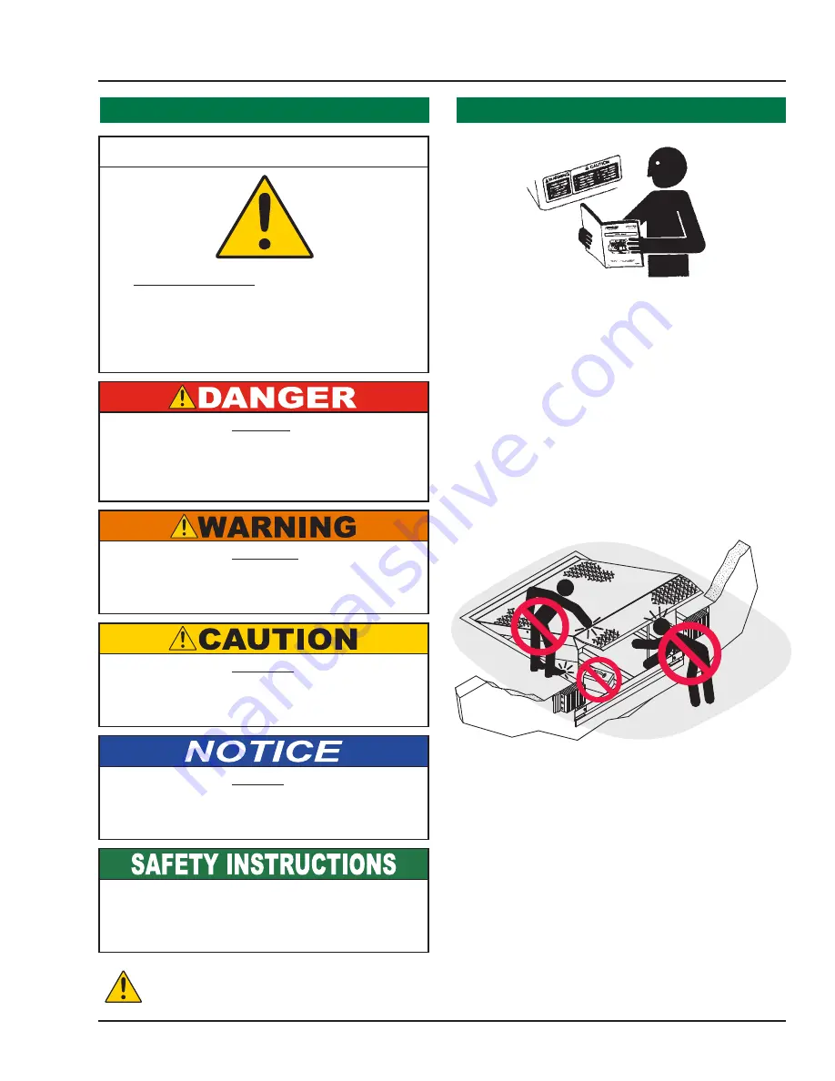
Safety-Alert Symbol

The Safety-Alert Symbol is a graphic representation 

intended to convey a safety message without the 

use of words. When you see this symbol, be alert 

to the possibility of death or serious injury. Follow 

the instructions in the safety message panel.

The use of the word DANGER signifies the 

presence of an extreme hazard or unsafe practice 

which will most likely result in death or severe 

injury.

The use of the word WARNING signifies the 

presence of a serious hazard or unsafe practice 

which could result in death or serious injury.

The use of the word CAUTION signifies possible 

hazard or unsafe practice which could result in 

minor or moderate injury.

The use of the word NOTICE indicates information 

considered important, but not hazard-related, to 

prevent machine or property damage.

Indicates a type of safety sign, or separate panel on 

a safety sign, where safety-related instructions or 

procedures are described.

Do not start the equipment until all unauthorized 

personnel in the area have been warned and have 

moved outside the operating zone (Figure 1).

Remove any tools or foreign objects from the 

operating zone before starting.

Keep the operating zone free of obstacles that could 

cause a person to trip or fall.

Summary of Contents for TPR UniLock

Page 1: ...Systems LLC W194 N11481 McCormick Drive Germantown WI 53022 800 643 5424 fax 262 255 5917 www poweramp com techservices poweramp com Printed in U S A 2018 Systems LLC All Rights Reserved Manual No 4111 0072 Dec 2018 Patent Pending Owner s User s Manual ...

Page 2: ...ing 17 Placard Installation Instructions 18 Operation Operational Precautions 19 Operation Normal 20 Operation Bypass 21 Multi Colored Outside Light Sequence Charts 22 Maintenance Maintenance Precautions 24 Periodic Maintenance 25 Adjustments Drive Chain Brake Torque Adjustments 26 Adjust Dock Leveler Vehicle Restraint Interlock 28 Troubleshooting Limit Switch Test Procedure 30 UniLock Harness Wir...

Page 3: ...alert to the possibility of death or serious injury Follow the instructions in the safety message panel The use of the word DANGER signifies the presence of an extreme hazard or unsafe practice which will most likely result in death or severe injury The use of the word WARNING signifies the presence of a serious hazard or unsafe practice which could result in death or serious injury The use of the...

Page 4: ... hands and feet clear of pinch points Avoid putting any part of your body near moving parts Chock restrain all transport vehicles Never remove the wheel chocks or release the restraining device until loading or unloading is finished and transport driver has been given permission to drive away Do not use a broken or damaged dock leveling device or restraining device Make sure proper service and mai...

Page 5: ...t use dock leveling device if transport vehicle is too high or too low Do not overload the dock leveling device Do not operate any equipment while under the influence of alcohol or drugs Do not leave equipment or material unattended on dock leveling device PRECAUTIONS ...

Page 6: ...ing unloading transport vehicle Area around RIG should be free of plates lift gates or other obstructions for hook to securely capture the RIG TPR UniLock Hook must securely capture Rear Impact Guard RIG Visually inspect before loading unloading transport vehicle Dock Face RIG Hook Lift Gates 1 50 3 00 Decal Size 1 5 x 3 File Name 1751 0736 Rev A Arc Flash and Shock Hazard PPE Personal Protection ...

Page 7: ... light communication system load and unload on GREEN light only 4 Maintenance or service must be performed by authorized personnel only Follow approved lockout tagout procedures FAILURE TO FOLLOW THESE INSTRUCTIONS WILL RESULT IN DEATH OR OTHER SERIOUS INJURY VEHICLE RESTRAINTS ENGAGE RESTRAINT 1 Open overhead door and visually check that transport vehicle is positioned squarely against dock bumpe...

Page 8: ...terations of restraining devices shall be made only with prior written approval from the original manufacturer These changes shall be in conformance with all applicable provisions of the MH30 3 standard and shall also satisfy all safety recommendations of the original equipment manufacturer of the particular application 6 An operator training program should consist of but not necessarily be limite...

Page 9: ...ufacturers recommendations are the sole responsibility of the owner user 10 Manufacturer s recommended maintenance and inspection of all restraining devices shall be performed in conformance with the following practices A planned maintenance schedule program must be followed only trained and authorized personnel shall be permitted to maintain repair adjust and inspect restraining devices and only ...

Page 10: ...s down to a stored position The UniLock vehicle restraint also has an internal safety mechanism that locks the restraint s hook in place when pressure is applied maintaining a secure engagement This makes it universally effective on any obstructed Rear Impact Guard RIG including intermodal trailers with cover plates that prevent the restraint s hook from latching on top of the RIG The UniLock is d...

Page 11: ...A U T I O N P U L L I N O R O U T O N G R E E N O N L Y Figure 4 4111 0072 Dec 2018 2018 Systems LLC Component Identification Inspect package and all components Report any missing or damaged items immediately and note on the shipping Bill Of Lading BOL INTRODUCTION Control box appearance may vary depending on options ...

Page 12: ... grinding or welding Post safety warnings and barricade the work area at dock level and ground level to prevent unauthorized use of the dock leveler before installation has been completed Only trained installation professionals with the proper equipment should install this product DO NOT connect the vehicle restraint electrical wiring and ground connections until all welding has been completed DO ...

Page 13: ...3 Supplied by others Dock Seal Inside light and control box Outside lights Inside Caution sign Place control box where best suited within arms reach at eye level near door opening Outside Caution Sign Optional imbed plated 20 x20 4 Thick Bumpers Disconnect supplied by others 58 Installation Overview Note This is a generic overview of a typical UniLock installation See full installation instruction...

Page 14: ... TPR vehicle restraint roller track interferes with the access hole the track plate must be cut to allow access Anchor Installation Note Fifteen 15 concrete anchors are provided with each TPR vehicle restraint An anchor must be installed in each roller track plate hole except for those plug welded to embedded steel 1 Place roller track at desired location spaced 5 8 above the drive 2 Using the rol...

Page 15: ...13 3 4111 0072 Dec 2018 2018 Systems LLC INSTALLATION Figure 6 Figure 7 ...

Page 16: ... Disconnect power and ground leads to dock leveler if equipped 2 Place roller track at desired location spaced 5 8 above the drive 3 Plug weld all holes that are in contact with embedded steel All fifteen 15 holes must be either plug welded or anchored 4 Weld the sides of the roller track plate to the embed mounting plate with 4 long 1 4 fillet welds 5 Weld across top of roller track plate to curb...

Page 17: ...15 3 4111 0072 Dec 2018 2018 Systems LLC INSTALLATION Figure 8 Figure 9 ...

Page 18: ...r plate 3 Remove motor cover D 4 Slide the carriage assembly E into the roller track F position and bolt the lower spring bar B to the bottom of the UniLock carriage 5 Install right and left spring covers G with clip nuts and flat head screws provided 6 Install the motor cover D 7 Install slope extension H Do not attempt to lift the carriage assembly by hand Use a lifting device e g crane jack whe...

Page 19: ...ain more than one power source Hazardous Voltage Will Result in Death or Serious Injury 1751 0736 Rev A 4111 0072 Dec 2018 2018 Systems LLC INSTALLATION 1 Mount the push button control panel B so bottom of control panel to dock floor distance C is 48 in 1219 mm See Figure 11 2 Install electrical disconnect panel A if not already installed Disconnect panel supplied by others 3 Install and connect t...

Page 20: ... view of dock leveler and or vehicle restraint operations Suggested placement of placard is near control box attached to electrical conduit by using nylon cable tie If there is no control box present mount placard on wall to the immediate left of leveler at eye level A B C D A Control Box B Placard C Nylon Cable Tie D Conduit Placard Installation Instructions Control Box Conduit Nylon Tie Placard ...

Page 21: ...ocedures have been performed on the equipment before using Transport vehicle wheels must be chocked unless the vehicle restraint is used Never remove the wheel chocks until loading unloading is finished and transport vehicle driver has been given permission to leave Make sure platform lip rests on the transport vehicle bed with at least 4 in 102 mm of overlap Maintain a safe distance from side edg...

Page 22: ... Inside light RED Outside light GREEN OPERATION Operation Auto Re Engage Note Auto Re Engage requires an iDock Control System Units without an iDock Control System do not have this functionality After restraint has been engaged with successful capture of RIG bar these restraints will automatically attempt to re engage if they leave the working zone When restraint hook is lowered to the stored posi...

Page 23: ...RMAL mode by pressing the RELEASE button once or through menu screens under OPERATION MODE Inside light RED Outside light GREEN 6 Release the transport vehicle wheels when transport vehicle is ready to depart Operation Bypass From Unsuccessful Engage If the restraint fails to successfully ENGAGE a trailer RIG the hook will automatically return to the stored position Inside light AMBER RED Outside ...

Page 24: ...on Condition Lights Inside Outside Restraint Engage Failure Bypass Mode prompt Red Amber Display Backlight Red Bypass Mode Green Amber Green Red on Dock Alert Red Reset Attempted Leveler in Use Red Amber Display Backlight Red Reset Attempted Door Open Green Amber Display Backlight Red Reset Lights to Normal Mode Red Display Backlight 5 seconds Green Bypass Mode Condition Lights Inside Outside Main...

Page 25: ...23 This page intentionally left blank 4111 0072 Dec 2018 2018 Systems LLC OPERATION ...

Page 26: ... and clearly state who is responsible for the lockout condition Refer to OSHA regulations 1910 146 Confined Space and 1910 147 Lockout Tagout Always post safety warnings and barricade the work area at dock level and ground level to prevent unauthorized use of the unit before maintenance is complete B A B A C D MAINTENANCE Unless the dock leveler is equipped with a tethered remote two people are re...

Page 27: ... box for water damage Control box and conduit for damage Light bulbs and lenses Bumpers for more than 1 of wear Replace worn loose damaged or missing bumpers Lubricate the rollers at the fittings located on the top and bottom axle with a synthetic oil base moly grease with a temperature range of 40 to 170 F Lubricate the hook weldment at the fitting with a synthetic oil base moly grease with a tem...

Page 28: ...closure and clean the chain with solvent After cleaning spray with a high quality chain spray type lubricant The drive chain should not have more than 1 4 slack see Figures 19 and 20 To tighten chain 1 Open motor enclosure and loosen the four 4 motor mounting bolts 2 Pry the motor assembly forward in the slotted holes until the chain is tight with proper alignment between sprockets 3 Hold in this ...

Page 29: ...igure 20 LOCKNUT BRAKE ADJUSTER SET SCREW USE TORQUE WRENCH LUBRICATE DRIVE CHAIN AND LIMIT SWITCH MOUNTING BRACKET USE SPRAY GREASE ZEP 2000 OR EQUAL Figure 19 45 DEGREES 96 IN LBS 4111 0072 Dec 2018 2018 Systems LLC ...

Page 30: ... operated until the leveler is stored in the cross traffic position lip fully folded inside the keepers and the platform level with the dock floor Interlocking is overridden when the OPERATION MODE is in BYPASS This allows the independent operation of the leveler the restraint cannot be operated in BYPASS MODE Pressing the restraint RELEASE button when in BYPASS mode will return the leveler to NOR...

Page 31: ... the target or bend the target to increase dimension B so that the target is not in the sensing range of the switch Make adjustments at switch and or target until vehicle restraint does not disengage transport vehicle See Figure 21 Note If adjustments are required in this step make sure that the interlocking described in Step 3 is still in effect after Step 6 adjustments are complete 7 Press the R...

Page 32: ...h the plunger released there should be no meter reading With the plunger Pressed there should be a full scale meter reading Note The green ground wire of the limit switch does not have to be tested A continuity test lamp may be used instead of a multimeter Figure 22 Figure 23 Hook Position LS1 Position LS2 Position Inside Outside Stored Closed Pressed Open Released Red Green No Hook Under Travel C...

Page 33: ...31 TROUBLESHOOTING TPR Harness Wire Identification Figure 24 Figure 25 4111 0072 Dec 2018 2018 Systems LLC ...

Page 34: ...round level to prevent unauthorized use of the dock leveler before maintenance is complete A hard hat or other applicable head protection should always be worn when working under or around a dock leveler Always stand clear of platform lip when working in front of the dock leveler Unless the dock leveler is equipped with a tethered remote two people are required to engage the maintenance prop one p...

Page 35: ... does not change Defective LS1 Outside lights and inside green light do not change Defective LS2 UniLock vehicle restraint carriage does not return to full up position Broken or weak springs Replace all springs Damaged roller track plate Verify that the roller track plate is straight and not binding or catching Carriage binding in track Clean debris out of roller track and or verify roller bearing...

Page 36: ...fac granted only by written authorization signed by an officer Decal Size 11 x 3 5 File Name 1751 1101 Black and Red on Clear www Powermap com 800 643 5424 39 33 37 36 2 12 16 9 20 22 28 29 26 42 34 31 48 38 14 14 26 17 47 23 5 27 30 4 3 13 18 11 6 15 7 8 24 21 49 32 39 43 21 1 46 49 44 45 40 Decal 1751 1102 Outside Black lines are not printed shows edge of decal Circle needs to be die cut black l...

Page 37: ...0110 Hook Shaft 23 2 9701 0209 Nut Lock 3 4 Conduit 24 1 9701 0114 Drive Sprocket Hook w Set Screw 26 8 9701 0211 Bolt Carriage 3 8 16 x 1 27 1 9701 0212 Cord Grip 28 1 9703 0022 Hook Weldment UniLock 29 1 9701 0106 Carriage Weldment 30 1 4301 0008 Wire Harness 31 1 9701 0115 Chain 32 1 3411 0050 Motor Assembly 33 1 1751 1101 Decal UniLock 34 1 0521 0201 Fitting Grease Zerk 1 8 NPT 36 1 1751 1102 ...

Page 38: ...OVER RIGHT HAND 2 1 9701 0100 ROLLER TRACK 3 4 9701 0216 NUT CAGE 5 16 18 4 4 0941 0016 EXTENSION SPRING 5 15 2101 0319 5 8 X 4 CONCRETE ANCHOR POWERS 6942 SD OR EQUIV 6 1 9701 0102 SPRING COVER LEFT HAND 7 4 2101 0069 SCREW SOCKET 5 16 18 1 1 4 FLAT HEAD 4111 0072 Dec 2018 2018 Systems LLC ...

Page 39: ... 0219 PIN SLOPE EXTENSION PIVOT 4 1 9701 0105 SPRING MOUNTING PLATE ASSEMBLY 5 2 9701 0220 NUT LOCK 7 16 14 SERRATED FLANGE 6 1 9701 0104 SLOPE EXTENSION 9701 0246 SLOPE EXTENSION WITH ROLLER OPTIONAL 7 1 9701 0103 CARRIAGE ASSEMBLY KIT INCLUDES 1 2 3 5 6 Slope Extensions Spring Plate 4111 0072 Dec 2018 2018 Systems LLC ...

Page 40: ...2 PROJECTION P O W E R A M P M C G U I R E D L M S Y S T E M S I N C L o a d i n g D o c k E q u i p m e n t This print is the property of Systems Inc and represents a proprietary article in which Systems Inc retains any and all patent and other rights including exclusive rights of use and or manufacture and or sale Possession of this print does not convey any permission to reproduce print or manu...

Page 41: ...11 Complete Light Housing Yellow Plastic With LED Lights 1 1 3051 0002 Light Housing Only Yellow Plastic 2 1 3051 0147 Red LED Lens Housing Circuit Assembly 12v 3 1 3051 0149 Green LED Lens Housing Circuit Assembly 12v 4 1 3051 0068 Mounting Gasket 5 4 3051 0105 Clip Lens Holding 6 4 3051 0104 Screw Lens Holding 7 1 Conduit Fastener 3 4 x 3 8 4111 0072 Dec 2018 2018 Systems LLC ...

Page 42: ...40 Signs Item Part Number Description 1 1751 0033 Outside Sign 2 1751 0034 Outside Sign Mirror Image 3 1751 0036 Inside Sign Enter On Green PARTS 2 1 3 4111 0072 Dec 2018 2018 Systems LLC ...

Page 43: ...he position of the parts Always give MODEL NUMBER and or SERIAL NUMBER For service call or contact Systems LLC P O Box 309 Germantown WI 53022 Phone 800 643 5424 Fax 262 255 5917 www loadingdocksystems com Dock Leveler Information Model ___________________________________ Serial No ________________________________ Systems LLC Job No ______________________ Vehicle Restraint Information Model ______...

Page 44: ... of maintenance Periodic lubrication adjustment and inspection in accordance with all manufacturers recommendations are the sole responsibility of the Owner User In the event of a defect as determined by SYSTEMS LLC covered by this warranty SYSTEMS LLC shall remedy such defect by repairing or replacing any defective equipment or parts bearing the cost for the parts labor and transportation This sh...

Reviews: