TP-Link TL-POE150S User Manual Download Page 8


Chapter 3 

Connecting the PoE Injector 

You can use TL-POE150S PoE Injector with PD or PoE Splitter 
to expand your network to where there are no power lines or 
outlets, where you wish to fix devices such as APs, IP Cameras 
or IP Phones, etc. The following steps will tell you how to 
connect the PoE Injector correctly.


1.  Use a CAT5 UTP cable to connect port of Ethernet device 

(such as a switch, hub or router) to the 

LAN IN

 port. 

2. Please connect the power adapter properly to a power 

socket with provided power cable, and then connect the 
other end of the power adapter to the 

DC 48V

 port of the 

TL-POE150S.  

3. Connect the 

POWER+DATA OUT

 port of the TL-POE150S 

to a PD or a PoE Splitter with CAT 5 UTP cable. 

Now, the device can work normally with data and power. 
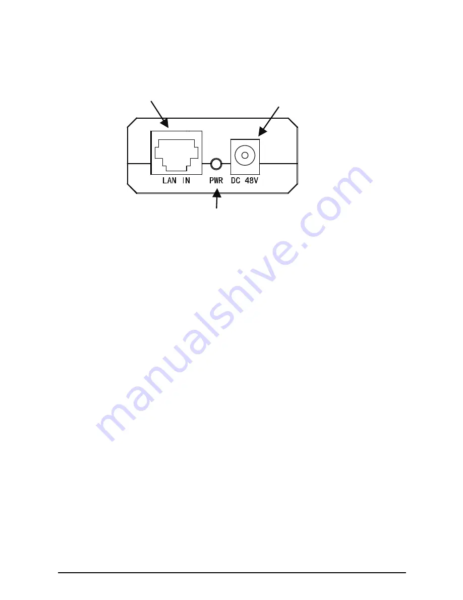
LAN IN:

 Connect to a 

network device (such as a 
Switch or Router ) with 
CAT5 UTP cable.

DC 48V:

Connect to the 

provided power adapter 
which can supply steady 
power of 48V DC. 

PWR:

 Power LED. 

A steady blend color of red and yellow 

indicates that 

the power adapter is working properly.

 A steady 

green light indicates that 

the PoE system has detected the 

PD or PoE Splitter

 and the PoE Injector is supplying power 

normally. A flashing light indicates abnormal power supply

Summary of Contents for TL-POE150S

Page 1: ...User Guide TL POE150S PoE Injector Rev 3 0 0 7106503937...

Page 2: ...are trademarks or registered trademarks of their respective holders No part of the specifications may be reproduced in any form or by any means or used to make any derivative such as translation tran...

Page 3: ...nt does cause harmful interference to radio or television reception which can be determined by turning the equipment off and on the user is encouraged to try to correct the interference by one or more...

Page 4: ...is a class B product In a domestic environment this product may cause radio interference in which case the user may be required to take adequate measures SAFETY NOTICES Do not use this product near wa...

Page 5: ...ENTS Package Contents 1 Chapter 1 Introduction 1 1 1 Overview of the Product 1 1 2 Features 2 Chapter 2 Identifying External Components 2 Chapter 3 Connecting the PoE Injector 3 Appendix Specification...

Page 6: ...er over Ethernet PoE Injector is able to supply steady power to Powered Device PD or PoE Splitter over the Ethernet cable The Ethernet equipment can work as a Power Sourcing Equipment PSE with the hel...

Page 7: ...mini size Chapter 2 Identifying External Components PoE This technology describes a system to transmit electrical power along with data to remote devices over standard twisted pair cable in an Ethern...

Page 8: ...cable and then connect the other end of the power adapter to the DC 48V port of the TL POE150S 3 Connect the POWER DATA OUT port of the TL POE150S to a PD or a PoE Splitter with CAT 5 UTP cable Now th...

Page 9: ...mple following topology will work Scheme 1 2 If the device does not support PoE it is necessary to have a PoE Splitter to separate the power and data transmitting them detached in one UTP cable and on...

Page 10: ...com Appendix Specifications Normal Standards IEEE 802 3 IEEE 802 3u IEEE 802 3ab IEEE 802 3af Ports 1 10 100 1000Mbps Auto Negotiation RJ45 LAN port 1 10 100 1000Mbps Auto Negotiation RJ45 PoE port 1...

Reviews: