background image


Package contents 

The following contents should be found in your box: 

¾


One TD-8811/TD-8811B External ADSL2+ ROUTER 

¾


One AC power Adapter for TD-8811/8811B External ADSL2+ ROUTER 

¾


One Resource CD for TD-8811/TD-8811B External ADSL2+ ROUTER, including: 


This User Guide 


Quick installation Guide Program 


Other Helpful Information 

 USB 

driver 

¾


Quick installation Guide   

¾

  One RJ45 cable 

¾

  Two RJ11 cable 

¾


One ADSL splitter (only available for TD-8811) 

¾


One USB cable 

)


Note: 

If any of the above items are damaged or missing, please contact the retailer from whom 

you purchased the TD-8811/TD-8811B External ADSL2+ ROUTER for assistance. 

Summary of Contents for TD-8811

Page 1: ...TD 8811 TD 8811B External ADSL2 ROUTER ...

Page 2: ...oduct names are trademarks or registered trademarks of their respective holders No part of the specifications may be reproduced in any form or by any means or used to make any derivative such as translation transformation or adaptation without permission from TP LINK TECHNOLOGIES CO LTD Copyright 2007 TP LINK TECHNOLOGIES CO LTD All rights reserved ...

Page 3: ...ined by turning the equipment off and on the user is encouraged to try to correct the interference by one or more of the following measures Reorient or relocate the receiving antenna Increase the separation between the equipment and receiver Connect the equipment into an outlet on a circuit different from that to which the receiver is connected Consult the dealer or an experienced radio TV technic...

Page 4: ...D 8811B External ADSL2 ROUTER including This User Guide Quick installation Guide Program Other Helpful Information USB driver Quick installation Guide One RJ45 cable Two RJ11 cable One ADSL splitter only available for TD 8811 One USB cable Note If any of the above items are damaged or missing please contact the retailer from whom you purchased the TD 8811 TD 8811B External ADSL2 ROUTER for assista...

Page 5: ...r 2 Chapter 2 Hardware Installation Guide 3 2 1 System requirement 3 2 2 LED explanation 3 2 3 Rear panel 4 2 4 Hardware installation procedures 4 Chapter 3 System Configuration 5 3 1 Computer Configuration 5 3 2 Login 7 3 3 Web Setup 9 3 4 Software Dial 18 3 5 USB Configuration 19 Chapter 4 Advantage management setup 22 Appendix A FQA 23 Appendix B Default Configuration 24 Appendix C Contact Info...

Page 6: ...main specification High speed and asymmetrical data transmit mode provides safe and exclusive bandwidth Supports All ADSL2 industrial standards Compatible with all mainstream DSLAM CO Firmware upgradeable Provides integrated access of internet and route function which face to SOHO users Advanced DMT modulation and demodulation Real time Configuration and device monitoring Quick response semi condu...

Page 7: ...software Full 24 bit Virtual Path Identifier VPI and Virtual Circuit Identifier VCI 1 5 System support Support PVC Support NAT DHCP and so on Support IEEE 802 3 IEEE 802 3u Support 10Base T 100BASE TX full duplex or half duplex Ethernet Support Auto MDIX Support USB 1 1 device interface 1 6 Working environment Operating temperature 0 40 Storage temperature 40 70 Humidity 10 90 non condensing 1 7 E...

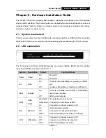
Page 8: ...DSL2 ROUTER includes one power indicator RED and five function indicators GREEN as explained in chart 1 1 Indicator Description Status Function Details Power Power On Off Power OK Power fail Act Data On Off There is data transmitting or receiving on WAN port No data is transmitting or receiving on WAN port Alarm Mistake On Off There is a mistake when ADSL is transmitting data or receiving data ADS...

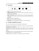
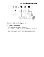
Page 9: ...he MODEM Port of Splitter or connect the telephone line 2 4 Hardware installation procedures The procedure to install the Router can be described in the following steps First Step Connect the MODEM port of Splitter with the LINE port of the TD 8811 TD 8811B ADSL2 ROUTER by telephone line Second Step Connect category 5 cable with RJ45 jacks to ADSL2 Router s LAN port and your computer s NIC Or conn...

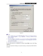
Page 10: ...onnect the cable according to Chapter 2 turn on the power 2 Change the IP address of your PC Figure 3 1 Open TCP IP Properties of the LAN card in your PC enter the IP address as 192 168 1 is any value between 2 to 254 Network mask is 255 255 255 0 Gateway is 192 168 1 1 DNS address is the value provided by ISP ...

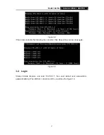
Page 11: ...users of Windows 2000 NT XP can do the following Right press Network Neighbor Choose Properties Right press Local Connection Choose Properties Double click Internet Protocol TCP IP 3 The words may be different with this guide in fact You can check whether your configuration is successful through PING command Enter Ping 192 168 1 1 If the screen looks like the following the connection between your ...

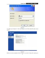
Page 12: ...creen looks like the following the connection fails Repeat the previous steps again Figure 3 3 3 2 Login Startup Internet Explorer and enter 192 168 1 1 then enter default user name admin password admin When ADSL2 connection is OK you will see the Figure 3 4 ...

Page 13: ...SL2 ROUTER 8 Figure 3 4 You will then see the Figure 3 5 This screen displays some information about the device such as link rate Figure 3 5 Default user name and password both are admin if you want to change them please go to ...

Page 14: ...etup Choose Advanced Setup Æ WAN you will enter the page of Wide Area Network WAN Setup you will see the Figure 3 7 Figure 3 7 There are 7 PVC links in the WAN setup page choose the right PVC according to your needs and then click the edit button you will enter the page of ATM PVC Configuration See Figure 3 8 ...

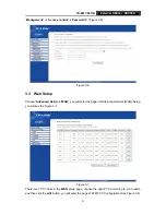
Page 15: ... be different in different areas there are five types Figure 3 9 so you should ask your ISP to acquire the local type of network protocol and Encapsulation mode Figure 3 9 After choosing the proper protocol enter the correct parameters supported by your ISP Enable the configurations then you can surf on the Internet PPP over ATM PPPoA If you select the protocol of PPP over ATM PPPoA you will see t...

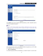
Page 16: ...other functions often using the default setup click the next button Figure 3 10 After that the Figure 3 11 will appear Turn on the selected functions according to your demands Clicking the next button to enter the next step you will see the Figure 3 12 finally click save to complete the configuration Figure 3 11 ...

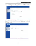
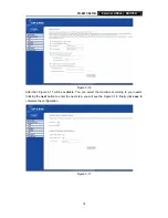
Page 17: ...alue of user name and password which is provided by your ISP after selecting other functions often using the default setup click the next button Figure 3 13 You will see the Figure 3 14 Then turn on the selected functions according to your needs Clicking the next button to enter the next step you will see the Figure 3 15 finally click save to complete the configuration ...

Page 18: ...3 Figure 3 14 Figure 3 15 MAC Encapsulation Routing MER If you select the protocol of MAC Encapsulation Routing MER you will see the page Figure 3 16 Enter the parameter and the way which is provided by your ISP then click the next button ...

Page 19: ...igure 3 16 After that Figure 3 17 will be available You can select the functions according to your needs Clicking the next button to enter the next step you will see the Figure 3 18 finally click save to complete the configuration Figure 3 17 ...

Page 20: ...will display enter the parameter and the way which is provided by your ISP then click the next button Figure 3 19 You will see the page Figure 3 20 then turn on the selected functions according to your needs Clicking the next button to enter the next step you will see the Figure 3 21 finally click save to complete the configuration ...

Page 21: ... 3 20 Figure 3 21 Bridging If you select the Bridging protocol you just open the bridge service function options you will see the Figure 3 22 then click the next button you will see the Figure 3 23 press save to complete the configuration finally ...

Page 22: ...OUTER 17 Figure 3 22 Figure 3 23 Note After you complete the settings the new settings must be saved and the Router must be restarted for the settings to take effect Please press the Save Reboot button on the Figure 3 24 to restart ...

Page 23: ...t the connect to the internet and then click the Next button to enter the next page and select the set up my connection manually click Next to enter the next page Please select the connect using a broadband connection that requires user name and password click Next to type the name of your ISP in the current page and then click Next Type an ISP account name and password if you have forgotten an ex...

Page 24: ...led before the computer is Power On Please turn on the computer and enter the operating system Then the operating system will identify the device If the hardware is installed after the computer is Power On the desktop will display the information about finding the new hardware Then you will see the Figure 3 25 require install software for USB Device select Install from a list or specific location ...

Page 25: ...al ADSL2 ROUTER 20 Figure 3 26 Select the search removable media floppy CD ROM and click the next button then Figure 3 27 is available The driver will be searched and installed Note You must insert the CD first Figure 3 27 ...

Page 26: ...tes click Finish to close the installation Please refer to chapter 3 1 to finish the IP configuration for USB connect Then you could use the USB device Figure 3 28 Note 1 All of the above settings are under windows XP 2 If you want to pull out the USB device you must disconnect the network of USB first ...

Page 27: ... are as follows Upgrade software Modify the default IP address of the port of LAN 192 168 1 1 Modify the login password Configure DHCP Check the information of IP and the operation status Configure the NAT function Configure the DNS parameters Configure RIP Routing Information Protocol Configure IP route Configure Security rule Configure DSL parameter Note If you want to acquire further details pl...

Page 28: ...clude LLC SNAP and VC_MAX often using LLC SNAP 3 The LAN s and the NIC s LED both are bright but why the configuration interface is inaccessible 1 Use the order of ping 192 168 1 1 to check the Accuracy of connection 2 Check the Accuracy of working NIC 3 Whatever the setup of the IP address on your computer if you close the DHCP function you can t obtain the IP address automatically must specify t...

Page 29: ...TD 8811 8811B External ADSL2 ROUTER 24 Appendix B Default Configuration USER NAME admin PASSWORD admin IP ADDRESS 192 168 1 1 VPI VCI 0 32 1 33 0 35 0 100 0 200 8 35 8 81 ...

Page 30: ...811B External ADSL2 ROUTER 25 Appendix C Contact Information For more help with the installation or operation of the TP LINK TD 8811 TD 8811B External ADSL2 ROUTER please contact us Website http www tp link com ...

Reviews: