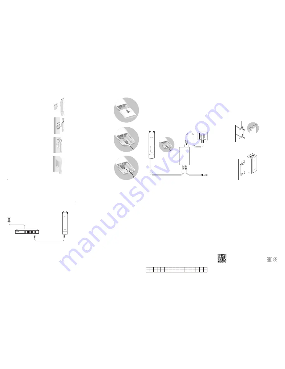
Option 3: Mounting the EAP on an Antenna
Step4:
Attach the protective cap. Push and
slide the protective cap down over the
EAP until it firmly locks into place.
Step1:
Align the mounting tabs on the back
of the EAP with the slot of the
mounting bracket (for EAP). Push and
slide the EAP downward until it locks
into place.
Step3:
Connect the RF cables from the EAP
to the corresponding connectors on
the antenna.
Note:
Sector antenna is used as a demonstration below.
Step2:
Align the mounting tabs on the
mounting bracket (for EAP) with the
four slots of the mounting bracket on
the antenna. Push and slide the EAP
downward until it locks into place.
Connect Cables
Firmly grasp the rear of the interface
cover and pull it downward.
Step 1:
Use an adequate Ethernet cable to
connect the LAN port. The length of
cable is up to 100m for steady
power supply. Shielded CAT5e (or
above) cable is recommended.
Step 2:
Attach the waterproof rubber insert
to the groove at the underside of
the device for waterproofing and
replace the cover until it firmly locks
into place.
Step 3:
Power On
The EAP can be powered via the provided passive PoE adapter or a
PSE device (such as a PoE switch) .
Via PoE Switch
PoE Switch
Connect an Ethernet cable from the PoE switch to the
ETHERNET port.
Step 1: Installing the EAP Controller
On the PC, download the EAP Controller installation file from
http://www.tp-link.com/en/download/EAP-Controller.html
. Run the
file and follow the wizard to install the EAP Controller.
Step 2: Configuring the EAP Controller
Launch the EAP Controller and follow the step-by-step instructions
to complete the Quick Setup. After the wizard is finished, a login
screen will appear.
Step 3: Logging in to the EAP Controller
Enter the admin name and password you created and click
Sign In
.
Then you can further configure the EAP Controller.
Software Configuration
To configure and manage mass EAPs via centralized controller software, please
refer to
Option 1
.
To configure a single EAP via a web browser directly, please refer to
Option 2
.
The EAP supports two configuring options:
Option 1: Via EAP Controller
For detailed configurations, please visit
http://www.tp-link.com/support
to download the User Guide of
EAP Controller in the download center.
Step 1: Connecting to the EAP Device
Power on the EAP and connect wirelessly by using the default SSID
(format: TP-Link_2.4GHz/5GHz_XXXXXX) printed on the product
label.
Option 2: Via Web Browser
Step 2: Logging in to the EAP Device
Launch a web browser and enter
http://tplinkeap.net
in the address
bar. Use
admin
for both Username and Password to log in.
For detailed configurations, please visit
http://www.tp-link.com/support
to download the User Guide of
EAP in the download center.
The products of TP-Link partly contain software code developed by third parties, including software code subject
to the GNU General Public License (“GPL”). As applicable, the terms of the GPL and any information on obtaining
access to the respective GPL Code used in TP-Link products are available to you in GPL-Code-Centre under
(http://www.tp-link.com/en/support/gpl/). The respective programs are distributed WITHOUT ANY WARRANTY and
are subject to the copyrights of one or more authors. For details, see the GPL Code and other terms of the GPL.
For technical support, User Guide and other information, please
visit http://www.tp-link.com/support, or simply scan the QR code.
Connect the EAP to a Power over Ethernet (PoE) adapter as follows:
Via Passive PoE Adapter
Connecting the PoE Adapter
PoE
LAN
Ethernet cable length up to 100m
Attention:
For EAP225-Outdoor, in EU member states and EFTA countries, the operation in
the frequency range 5150MHz - 5350MHz is only permitted indoors.
For EAP Controller, go to
Access Point
page and select the desired EAP to specify
the channel. For web browser, go to
Wireless > Wireless Settings
to specify the
channel.
AT BE BG CH
CY
CZ DE DK EE EL ES FI FR HR HU IE
IS IT LI LT LU LV MT NL NO PL PT RO SE SI SK UK
Sector or omni antennas need to be purchased additonally.
TL-ANT2415MS/TL-ANT5819MS/TL-ANT2410MO are available for the EAP.
Step 3: Configuring the EAP device
Set up a new Username and Password for secure management
purpose. Modify the wireless parameters and reconnect your
wireless devices to the new wireless network.
Mounting the PoE Adapter (Optional)
Note
: To ensure the passive PoE adapter is attached most securely, it is
recommended to install the adapter with the Ethernet port facing
upward.
Step 1:
Remove the mounting bracket from the passive PoE Adapter.
Drill two holes on the wall and insert the plastic wall anchors
into the the holes. Secure the mounting bracket to the wall.
Make sure the shoulders at the corners of the mounting bracket
are on the outside and pointing upward.
Step 2:
Attach the passive PoE adapter to the mounting bracket (for
PoE Adapter) by sliding the adapter in the direction of the
arrows until it locks into place.


