background image

FI-68

EFI SYSTEM — Air Induction System

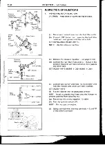
I NSPECTION OF ISC VALVE

1.

INSPECT ISC VALVE RESISTANCE

Using an ohmmeter, measure the resistance between ter-
minal B1 — S1 or S3, and B2 — S2 or S4.

Resistance: B1 - 51 or S3 10 - 30

B2 - S2 or S4 10 - 30

If resistance is not as specified, replace the ISC valve.

2.

INSPECT ISC VALVE OPERATION

(a)

Apply battery voltage to terminals B1 and B2, and
while repeatedly grounding S1 — S2 — S3 — S4 — S1

in sequence, check that the valve moves toward the

closed position.

(b)

Apply battery voltage to terminals B1 and B2, and
while repeatedly grounding S4 — S3 — S2 — S1 — S4

in sequence, check that the valve moves toward the
opened position.

If operation is not as specified, replace the ISC valve.

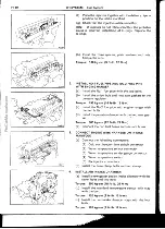
I NSTALLATION OF ISC VALVE

1. INSTALL ISC VALVE

Install a new gasket and ISC valve with the two bolts.

Torque: 120 kg-cm (9 ft-lb, 12 N•m)

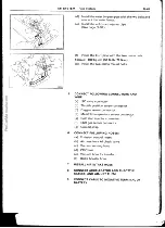
2.

CONNECT TWO WATER BY-PASS AND AIR

HOSES

3.

CONNECT ISC VALVE CONNECTOR

4.

FILL WITH ENGINE COOLANT

ProCarManuals.com

Summary of Contents for 3F-E

Page 1: ...ProCarManuals com ...

Page 2: ...ngine Repair Manual Pub No 36253E Please note that the publications below have also been pre pared as relevant service manuals to the components and systems in this engine Manual Name Pub No 3F E Engine Emission Control ERM045E Repair Manual All information in this manual is based on the latest product information at the time of publication However specifica tions and procedures are subject to cha...

Page 3: ...NTRODUCTION ENGINE MECHANICAL EFI SYSTEM COOLING SYSTEM I GNITION SYSTEM CHARGING SYSTEM SERVICE SPECIFICATIONS STANDARD BOLT TORQUE SPECIFICATIONS SST AND SSM 1993 TOYOTA MOTOR CORPORATION All rights reserved This book may not be repro duced or copied in whole or in part without the written permission of Toyota Motor Corporation ProCarManuals com ...

Page 4: ...e HOW TO USE THIS MANUAL IN 2 I DENTIFICATION INFORMATION IN 4 GENERAL REPAIR INSTRUCTIONS IN 4 PRECAUTIONS FOR VEHICLES EQUIPPED WITH A CATALYTIC CONVERTER IN 7 ABBREVIATIONS USED IN THIS MANUAL IN 8 I N I ProCarManuals com ...

Page 5: ...uide you to the item to be repaired At the beginning of each section PRECAUTIONS are given that pertain to all repair operations contained in that section Read these precautions before starting any repair task TROUBLESHOOTING tables are included for each system to help you diagnose the problem and find the cause The repair for each possible cause is referenced in the remedy column to quickly lead ...

Page 6: ...y and the text below it provides detailed information Important specifica tions and warnings always stand out in bold type Torque Specification 1 REFERENCES References have been kept to a minimum However when they are required you are given the page to refer to SPECIFICATIONS Specifications are presented in bold type throughout the text where needed You never have to leave the procedure to look up...

Page 7: ... which is grounded to the vehicle body c To prevent damage to the battery terminal post loosen the terminal nut and raise the cable straight up without twisting or prying it d Clean the battery terminal posts and cable terminal with a shop rag Do not scrape them with a file or such e Install the cable terminal to the battery post with the nut loose and tighten the nut after installation Do not use...

Page 8: ... specified and follow the proper work procedure A list of SST and SSM can be found at the back of this manual 1 0 When replacing fuses be sure the new fuse is the correct amperage rating DO NOT exceed the rating or use one of a lower rating 11 Care must be taken when jacking up and supporting the vehicle Be sure to lift and support the vehicle at the proper locations a If the vehicle is to be jack...

Page 9: ...the wire connector insert the tester probe carefully to prevent terminals from bending g When using a vacuum gauge never force the hose onto a connector that is too large Use a step down adapter instead Once the hose has been stretched it may leak 1 3 Tag hoses before disconnecting them a When disconnecting vacuum hoses use tags to identify how they should be reconnected b After completing a job d...

Page 10: ... to your customer 1 Use only unleaded gasoline 2 Avoid prolonged idling Avoid running the engine at idle speed for more than 20 minutes 3 Avoid spark jump test a Perform a spark jump test only when absolutely necessary and as quickly as possible b Never race the engine while testing 4 Avoid prolonged engine compression measurement Engine compression tests must be made as quickly as possible 5 Do n...

Page 11: ...ectronic Spark Advance EX Exhaust manifold valve iG Ignition IN Intake manifold valve ISC Idle Speed Control OHV Over Head Valve 0 S Oversize PCV Positive Crankcase Ventilation PS Power Steering SSM Special Service Materials SST Special Service Tools STD Standard SW Switch TCCS TOYOTA Computer Controlled System TDC Top Dead Center U S Undersize VCV Vacuum Control Valve VSV Vacuum Switching Valve V...

Page 12: ...36253E NOTE The following pages contain only the points which differ from the above listed manual DESCRIPTION TROUBLESHOOTING ENGINETUNE UP I DLE HC CO CONCENTRATION CHECK METHOD I NSPECTION AND ADJUSTMENT OF DASH POT DP SETTING SPEED COMPRESSIONCHECK CYLINDERHEAD TIMINGGEARS AND CAMSHAFT CYLINDERBLOCK ProCarManuals com ...

Page 13: ...ENGINE MECHANICAL Description EM 2 DESCRIPTION The 3F E engine is an in line 6 cylinder 4 0 liter OHV 12 valve engine ProCarManuals com ...

Page 14: ...stened to neither the piston boss nor the connect ing rods Instead snap rings are fitted on both ends of the pins preventing the pins from falling out The No 1 compression ring is made of steel and the No 2 compression ring is made of cast iron The oil ring is made of a combination of steel and stain less steel The outer diameter of each piston ring is slightly larger than the diameter of the pist...

Page 15: ...rm spark test IG 5 Ignition coil Igniter Distributor Spark plug faulty Inspect plugs IG 6 High tension cords disconnected broken Inspect cords IG 6 Vacuum leaks Repair as necessary PCV line EGR line Intake manifold Air intake chamber Throttle body ISC valve Brake booster line Pulling in air between air flow meter and throttle body Repair as necessary Low compression Check compression EM 16 ROUGH I...

Page 16: ...IDLING Cont d Problem Possible cause Remedy Page Rough idle stalls or Throttle body misses Cont d ISC valve Brake booster line Pulling in air between air flow meter and throttle body Incorrect idle speed Check ISC system FI 40 67 ProCarManuals com ...

Page 17: ...ir as necessary Vacuum leak PCV line e EGR line Check hoses and repair as necessary Intake manifold Air intake chamber Throttle body ISC valve Brake booster line Pulling in air between air flow meter and throttle body Repair as necessary Insufficient fuel flow Troubleshoot fuel system FI 9 Incorrect ignition timing Reset timing EM 11 Incorrect valve clearance Adjust valve clearance EM 10 Carbon de...

Page 18: ...em FI 40 67 Spark plug faulty Inspect plugs IG 6 EGR system always on Check EGR system Low compression Check compression EM 16 Tires improperly inflated Inflate tires to proper pressure Brakes drag Troubleshoot brakes UNPLEASANT ODOR Problem Possible cause Remedy Page Unpleasant odor Incorrect idle speed Check ISC system FI 40 67 Incorrect ignition timing Reset timing EM 11 Vacuum leaks Repair as ...

Page 19: ...and the coolant should be free from oil If excessively dirty replace the coolant I NSPECTION OF ENGINE OIL 1 CHECK ENGINE OIL QUALITY Check the oil for deterioration entry of water discoloring or thinning If the quality is poor replace the oil Use API grade SC SD SE SF or better and recom mended viscosity oil 2 CHECK ENGINE OIL LEVEL The oil level should be between the L and F marks on the dipstic...

Page 20: ...e not loose or corroded b Check the fusible links and fuses for continuity I NSPECTION OF HIGH TENSION CORDS 1 CAREFULLY REMOVE HIGH TENSION CORDS BY THEIR RUBBER BOOTS FROM SPARK PLUGS NOTICE Pulling on or bending the cords may damage the conductor inside 2 INSPECT HIGH TENSION CORD RESISTANCE Using an ohmmeter measure the resistance without dis connecting the distributor cap Maximum resistance 2...

Page 21: ...ER TO TDC COMPRESSION a Align the TDC mark of the drive plate with the tim ing pointer by turning the crankshaft clockwise with a wrench b Check that the rocker arms on the No 1 cylinder are loose and rocker arms on the No 6 are tight If not turn the crankshaft one revolution 360 and align the mark as above 4 INSPECT AND ADJUST VALVE CLEARANCE a Measure only those valves indicated by arrows Valve ...

Page 22: ...mperature 2 CONNECT TACHOMETER AND TIMING LIGHT TO ENGINE Connect the tachometer test probe to terminal IGS of the check connector NOTICE NEVER allow the tachometer terminals to touch ground as it could result in damage to the igniter and or ignition coil As some tachometers are not compatible with this ignition system we recommend that you confirm the compatibility of your unit before using 0 00 ...

Page 23: ...ing on the drive plate is aligned with the 7 mark d Tighten the distributor bolt and recheck the ignition ti ming Torque 175 kg cm 13 ft lb 17 N m e Remove the service wire 4 FURTHER CHECK IGNITION TIMING Ignition timing 12 BTDC idle Transmission in N range 5 DISCONNECT TACHOMETER AND TIMING LIGHT FROM ENGINE ProCarManuals com ...

Page 24: ...lly plugged Ignition timing set correctly Transmission in N range Tachometer and HC CO meter at hand and cali brated 2 START ENGINE 3 CHECK OXYGEN SENSORS OPERATION a Using a service wire connect terminals TE1 and El of the check connector b Connect the positive probe of a voltmeter to terminal VF1 VF2 of the check connector and negative probe to terminals El c Hold the engine speed at 2 500 rpm f...

Page 25: ...ition Incorrect timing Fouled shorted or improperly gapped plugs Open or crossed high tension cords Cracked distributor cap 2 Incorrect valve clearance 3 Leaky EGR valve 4 Leaky intake and exhaust valves 5 Leaky cylinder High Low Rough idle 1 Vacuum leak Fluctuating HC reading PCV hose EGR valve Intake manifold Air intake chamber Throttle body ISC valve Brake booster line 2 Lean mixture causing mi...

Page 26: ...ain engine speed at 2 500 rpm b Plug the VTV hole with your finger c Release the throttle valve d Check that the DP is set DP setting speed 1 200 rpm If not as specified adjust with the DP adjusting screw EC2724 Approx 1 Second RPM Release Tachometer EC2728 EC0141 6 CHECK OPERATION OF VTV a Set the DP speed in the same procedure as above a to c b Release the plugged hole and check that the engine ...

Page 27: ... must be done for as short a time as possible d Repeat steps a through c for each cylinder Compression pressure 10 5 kg cm 149 psi 1 030 kPa or more Minimum pressure 8 0 kg cm2 114 psi 785 kPa Difference between each cylinder 0 5 kg cm 2 7 psi 49 kPa or less e If compression of one or more cylinders is low pour a small amount of engine oil into that cylinder through the spark plug hole and repeat ...

Page 28: ...e page EM 28 Valve Rocker Shaft 1 Assembly Keeper S prin g Retainer IN Valve Rotator EX Push Rod Valve Spring __ Oil Seal Spring Seat Valve Guide Bushing Union 1 250 90 123 EGR Pipe Air Intake Chamber Stay Cylinder Head No 2 Fuel Pipe with Engine Hanger Pulsation P o Damper I njector Water Outlet Assembly I Delivery Pipe Intake Manifold C See page EM 30 Gasket x See page EM 30 Air Pump Stay No 2 H...

Page 29: ...d air pump stay c Remove the through bolt nut and air pump 5 REMOVE DELIVERY PIPE AND INJECTORS See steps 4 to 9 on pages FI 56 and 57 6 REMOVE AIR INJECTION MANIFOLD Remove the two bolts four union nuts and air injection manifold 7 REMOVE INTAKE AND EXHAUST MANIFOLDS a Remove the two bolts and manifold stay b Remove the six bolts and three manifold heat insu lators c Remove the ten bolts four nut...

Page 30: ...RK PLUGS 10 REMOVE CYLINDER HEAD COVER Remove the four cap nuts seal washers cylinder head cover and gasket 11 REMOVE VALVE ROCKER SHAFT ASSEMBLY a Uniformly loosen and remove the eight bolts and four nuts in several passes in the sequence shown b Remove the rocker shaft assembly 12 REMOVE PUSH RODS Remove the twelve push rods in order beginning from the No 1 push rod HINT Arrange the push rods in...

Page 31: ...olts in incorrect order b Remove the air pump bracket with engine hanger c Lift the cylinder head from the dowels on the cylin der block and place it on wooden blocks on a bench HINT If the cylinder head is difficult to lift off pry with a screwdriver between the cylinder head and block saliences NOTICE Be careful not to damage the cylinder head and block surface on the cylinder and head gasket si...

Page 32: ...ASSEMBLY OF CYLINDER HEAD See page EM 17 1 REMOVE AIR INJECTION MANIFOLD UNIONS 2 REMOVE VALVES a Using SST press the valve springs and remove the two keepers SST 09202 43013 b Remove the spring retainer or valve rotator valve springs and valve c Using a screwdriver pry out the valve stem oil seal d Remove the valve spring seat ProCarManuals com ...

Page 33: ...following dimensions and install an oversized bush ing 0 S 0 05 Rebored cylinder head bushing bore dimension 14 050 14 068 mm 0 5531 0 5539 in If the bushing bore diameter of the cylinder head is greater than 14 068 mm 0 5539 in replace the cylin der head c Using SST and a hammer drive in a new valve guide bushing so it is protruding 17 3 17 7 mm 0 681 0 697 in from the cylinder head SST 09201 600...

Page 34: ... valve head margin thickness is less than minimum replace the valve d Check the valve overall length Standard overall length Intake 124 8 mm 4 913 in Exhaust 128 0 mm 5 039 in Minimum overall length Intake 124 3 mm 4 894 in Exhaust 127 5 mm 5 020 in If the valve overall length is less than minimum replace the valve e Check the surface of the valve stem tip for wear If the valve stem tip is worn re...

Page 35: ...he valve seat the guide and seat are concentric If not resurface the seat Check that the seat contact is on the middle of the valve face with the following width Intake 1 1 1 7 mm 0 043 0 067 in Exhaust 1 4 2 0 mm 0 055 0 079 in If not correct the valve seat as follows 1 Intake If the seating is too high on the valve face use 25 IN and 45 cutters to correct the seat 2 If the seating is too low on ...

Page 36: ...measure the surfaces contacting the cylinder head and air intake chamber for warpage Maximum warpage 0 50 mm 0 0197 in If the warpage is greater than maximum replace the manifold 17 INSPECT AIR INTAKE CHAMBER Using a precision straight edge and thickness gauge measure the surfaces contacting the intake manifold for warpage Maximum warpage 0 2 mm 0 008 in If the warpage is greater than maximum repl...

Page 37: ... retainer or valve rotator HINT Install the spring in the correct direction as shown EM 26 ENGINE MECHANICAL Cylinder Head ASSEMBLY OF CYLINDER HEAD See page EM 17 HINT Thoroughly clean all parts to be assembled Before installing the parts apply new engine oil to all sliding and rotating surfaces Replace all gaskets and oil seals with new ones ProCarManuals com ...

Page 38: ...3 ENGINE MECHANICAL Cylinder Head EM 27 HINT Different keepers are used for the spring retainer w Spring Retainer and valve rotator w Valve Rotator EM1540 EM1541 2 INSTALL AIR INJECTION MANIFOLD UNIONS e Using a plastic faced hammer lightly tap the valve stem tip to assure proper fit ProCarManuals com ...

Page 39: ...mly tighten the ten cylinder head bolts with the plate washers in several passes in the sequence shown Torque 1 250 kg cm 90 ft lb 123 N m 2 INSTALL PUSH RODS Install the twelve push rods 3 INSTALL VALVE ROCKER SHAFT ASSEMBLY a Place the rocker shaft assembly on the cylinder head b Align the rocker arm adjusting screws with the heads of the push rods c Install and uniformly tighten the eight bolts...

Page 40: ...es indicated by arrows Valve clearance Intake 0 20 mm 0 008 in Exhaust 0 35 mm 0 014 in NOTE After warm up readjust the valve clearance Using a thickness gauge measure the valve clear ance between the valve stem and rocker arm Loosen the lock nut and turn the adjusting screw to set the proper clearance Hold the adjusting screw in position and tighten the lock nut Recheck the valve clearance The th...

Page 41: ... four plate washers and nuts Torque the bolts and nuts Torque 17 mm bolt A 700 kg cm 51 ft lb 69 N m 14 mm bolt B 510 kg cm 37 ft lb 50 N m Nut C 570 kg cm 41 ft lb 56 N m c Install the three manifold heat insulators with the six bolts Torque 120 kg cm 9 ft lb 12 N m d Install the manifold stay with the two bolts Torque 300 kg cm 22 ft lb 29 N m 9 INSTALL AIR INJECTION MANIFOLD Install the air inj...

Page 42: ...he air pump stay with the bolt and nut c Connect the air hose 12 CONNECT HIGH TENSION CORDS TO SPARK PLUGS AND IGNITION COIL 13 INSTALL PS PUMP BRACKETS 14 REFILL WITH ENGINE COOLANT Capacity w Front heater 17 5 liters 18 5 US qts 15 4 Imp qts w Front and rear heaters 19 5 liters 20 6 US qts 17 2 Imp qts ProCarManuals com ...

Page 43: ...er EM4521 Power Steering Pulley Gasket Timing Gear Cover Oil Seal Crankshaft Pulley 3 500 253 343 Specified torque ENGINE MECHANICAL Timing Gears and Camshaft TIMING GEARS AND CAMSHAFT COMPONENTS ProCarManuals com ...

Page 44: ... PS BRACKETS 4 REMOVE DISTRIBUTOR 5 REMOVE VALVE ROCKER SHAFT ASSEMBLY See steps 10 to 12 on pages EM 19 6 REMOVE PUSH ROD COVER Remove the ten bolts two nuts push rod cover and gasket 7 REMOVE VALVE LIFTERS Remove the twelve valve lifters in order beginning from the No 1 valve lifter EM4349 HINT Arrange the valve lifters in correct order 1 2 3 4 5 6 7 8 9 10 11 12 1 E M 1 344 ProCarManuals com ...

Page 45: ...ER PIPE WITH HOSE 11 REMOVE TIMING GEAR COVER Remove the twelve bolts gear cover and gasket 12 CHECK TIMING GEAR BACKLASH Using a dial indicator measure the backlash at several places while turning the camshaft clockwise and coun terclockwise Standard backlash 0 100 0 183 mm 0 0039 0 0072 in Maximum backlash 0 25 mm 0 0098 in If the backlash is greater than maximum replace the camshaft timing gear...

Page 46: ...09213 00030 09213 00090 15 IF NECESSARY REMOVE OIL NOZZLE b Carefully pull out the camshaft and timing gear as sembly NOTICE Be careful not to damage the camshaft bearing W ENGINE MECHANICAL Timing Gears and Camshaft EM 35 13 REMOVE CAMSHAFT TIMING GEAR AND CAMSHAFT ASSEMBLY a Remove the two bolts mounting the thrust plate to the cylinder block EM4505 ProCarManuals com ...

Page 47: ... timing gear SST 09214 60010 d Using a plastic faced hammer tap in the crankshaft pulley set key 2 INSTALL CAMSHAFT TIMING GEAR AND CAMSHAFT ASSEMBLY a Set the crankshaft timing gear with the key groove facing upward by turning the crankshaft clockwise b Insert the camshaft into the cylinder block NOTICE Be careful not to damage the camshaft bearings c Align the timing marks of the crankshaft and ...

Page 48: ...d coun terclockwise Standard backlash 0 100 0 183 mm 0 0039 0 0072 in Maximum backlash 0 25 mm 0 0098 in F W EM4356 Adhesive A 14 mm Bolt Head B 10 mm Bolt Head EItIIIII1J J C 10 mm Bolt Head E M 1358 4 INSTALL OIL NOZZLE a Install and set the oil nozzle in position b Using a chisel and hammer stake the threads of the oil nozzle 5 INSTALL TIMING GEAR COVER AND CRANKSHAFT PULLEY HINT There are thre...

Page 49: ...9213 58011 and 09330 00021 Torque 3 500 kg cm 253 ft lb 343 N m 6 INSTALL PS PULLEY TO CRANKSHAFT PULLEY Install the PS pulley with the six bolts Torque the bolts Torque 185 kg cm 13 ft lb 18 N m 7 INSTALL AND ADJUST DRIVE BELTS Check the drive belt deflection by pressing on the belt at the points indicated in the figure with 10 kg 22 0 lb 98 N of pressure Drive belt deflection Alternator to water...

Page 50: ...y groove After installing a new belt run the engine for about 5 minutes and then recheck the deflection tension 8 INSTALL VALVE LIFTERS Carefully insert the twelve lifters into the lifter bore R 9 INSTALL PUSH ROD COVER Install a new gasket and the push rod cover with the ten bolts and two nuts Torque 40 kg cm 35 in Ib 3 9 N m ENGINE MECHANICAL Timing Gears and Camshaft EM 39 CORRECT WRONG Clearan...

Page 51: ...1 Compression Piston Ring Side Rail Piston Snap Ring Piston Ring No 2 Compression Piston Ring Expander 600 43 59 Cylinder Block Drive Plate kg cm ft lb N m Non reusable part Precoated part Specified torque EM4483 890 64 87 EM 40 ENGINE MECHANICAL Cylinder Block CYLINDER BLOCK COMPONENTS ProCarManuals com ...

Page 52: ...LEARANCE a Uniformly loosen and remove the main bearing cap bolts in several passes in the sequence shown b Using the removed main bearing cap bolts wiggle the cap back and forth and remove the caps lower bearings and lower thrust washers No 3 cap only HINT Keep the lower bearing and main bearing cap together Arrange the main bearing caps and lower thrust wash ers in correct order c Lift out the c...

Page 53: ...placing the cylinder block subassembly the bearing standard clearance will be 0 004 0 060 mm 0 002 0 0024 in If the oil clearance is greater than maximum replace the bearings If necessary grind or replace the crankshaft HINT If replacing a standard size bearing with a stan dard oil clearance replace with one having the same number If the number of the bearing cannot be deter mined select a bearing...

Page 54: ...488 68 496 mm 2 6964 2 6967 in No 3 69 988 69 996 mm 2 7554 2 7557 in No 4 71 488 71 496 mm 2 8145 2 8148 in Cylinder block main journal bore diameter Mark 6 No 1 72 010 72 018 mm 2 8350 2 8353 in No 2 73 510 73 518 mm 2 8941 2 8944 in No 3 75 010 75 018 mm 2 9531 2 9535 in No 4 76 510 76 518 mm 3 0122 3 0125 in Mark 7 No 1 72 018 72 026 mm 2 8353 2 8357 in No 2 73 518 73 526 mm 2 8944 2 8947 in N...

Page 55: ...ove the Plastigage I NSPECTION OF CYLINDER BLOCK 5 INSPECT CYLINDER BORE DIAMETER Using a cylinder gauge measure the cylinder bore di ameter at positions A B and C in the thrust and axial directions HINT There are 3 standard sizes for the cylinder bore diameter which are marked on the cylinder block as shown in the illustration Standard diameter STD size Mark 1 94 000 94 010 mm 3 7008 3 7012 in Ma...

Page 56: ...387 3 7399 in O S 1 50 95 463 95 493 mm 3 7584 3 7596 in Front Thrust Direction O TAxial Direction A 1 0mm B 0 39 in Middle 1 0 mm 0 39 in EM0086 EM0365 b Measure the cylinder bore diameter in thrust direc tions See step 5 on page EM 44 c Subtract the piston diameter measurement from the cylinder bore diameter measurement Oil clearance 0 027 0 047 mm 0 0011 0 0019 in If the oil clearance is not wi...

Page 57: ...aximum even with a new piston ring rebore the cylinder and use an 0 S piston ring 6 INSPECT CONNECTING RODS a Using a rod aligner and thickness gauge check the connecting rod alignment Check for bend Maximum bend 0 05 mm 0 0020 in per 100 mm 3 94 in If bend is greater than maximum replace the connecting rod assembly Check for twist Maximum twist 0 15 mm 0 0059 in per 100 mm 3 94 in If twist is gre...

Page 58: ... rings with ones to match the over sized pistons 1 SELECT OVERSIZED PISTONS Oversized piston diameter 0 5 0 50 94 463 94 493 m m 3 7190 3 7202 in O S 1 00 94 963 94 993 m m 3 7387 3 7399 in O S 1 50 95 463 95 493 m m 3 7584 3 7596 in 2 CALCULATE AMOUNT TO BORE CYLINDER a Using a micrometer measure the piston diameter at a right angle to the piston pin hole center line 16 mm 0 63 in below the skirt...

Page 59: ...ankshaft bolt holes of any residual sealer oil or foreign particles Remove any oil with kerosene or gasoline b Apply adhesive to two or three threads of the mount bolt end Adhesive Part No 08833 00070 THREE BOND 1324 or equivalent HINT This sealant will not harden while exposed to air It will act as a sealer or binding agent only when ap plied to threads etc when the air is cut off c Install the d...

Page 60: ...ody Idle Speed Control ISC Valve ELECTRONIC CONTROL SYSTEM Location of Electronic Control Parts EFIMain Relay CircuitOpening Relay Cold Start Injector Time Switch Water Temperature Sensor High Temperature Line Pressure Up System OxygenSensors Electronic Controlled Unit ECU FuelCut RPM Page FI 2 FI 4 FI 4 FI 9 FI 21 FI 27 FI 44 FI 44 FI 50 FI 53 FI 55 FI 62 FI 62 FI 64 FI 67 FI 69 FI 69 FI 70 FI 71...

Page 61: ...sure Regulator Air Flow Meter II Fuel Tank Fuel Filter Throttle Position Sensor ISC Valve VSV For EGR Air Temp Sensor ASV Air Pump Oxygen Sensor Cold Start Injector Time Switch Water Temp Switch Water Temp Sensor ECU O Ignition Switch Speed mil Sensor Check Connector Terminal TE1 Battery CHECK Engine Light Neutral Start Switch Starter Coil Igniter 0 4WD Switch ProCarManuals com ...

Page 62: ...m problem Repair as necessary Vacuum leak Check hoses and repair as PCV line necessary EGR line Intake manifold Air intake chamber Throttle body ISC valve Brake booster line Pulling in air between air flow meter Repair as necessary and throttle body Insufficient fuel flow Troubleshoot fuel system FI 9 Incorrect ignition timing Reset timing EM 11 Incorrect valve clearance Adjust valve clearance EM ...

Page 63: ...ECAUTIONS WHEN CONNECTING GAUGE a Use the battery as the power source for the timing li ght tachometer etc b Connect the test probe of a tachometer to the termi nal IG e of the check connector 3 IN EVENT OF ENGINE MISFIRE FOLLOWING PRECAUTIONS SHOULD BE TAKEN a Check proper connection of battery terminals etc b Handle high tension cords carefully c After repair work check that the ignition coil te...

Page 64: ... are touched the IC may be destroyed by static electricity AIR INDUCTION SYSTEM 1 Separation of the engine oil dipstick oil filler cap PCV hose etc may cause the engine to run out of tune 2 Disconnection looseness or cracks in the parts of the air induction system between the air flow meter and cylinder head will allow air suction and cause the engine to run out of tune ELECTRONIC CONTROL SYSTEM 1...

Page 65: ... rubber if it is a water proof type connector b Insert the test probe into the connector from the wiring side when checking continuity amperage or voltage c Do not apply unnecessary force to the terminal d After checking install the water proofing rubber on the connector securely 9 Use SST for inspection or test of the injector cold start injector or its wiring connector SST 09842 30050 and 09842 ...

Page 66: ...observe the following procedure Union Bolt Type a Always use a new gasket b Tighten the union bolt by hand c Tighten the union bolt to the specified torque Torque 300 kg cm 22 ft lb 29 N m Flare Nut Type a Apply a light coat of engine oil to the flare and tighten the flare nut by hand b Using SST tighten the flare nut to specified torque SST 09631 22020 Torque 310 kg cm 22 ft lb 30 N m HINT Use a ...

Page 67: ...topped turn the ignition switch ON b Using a service wire short terminals B and FP of the check connector c When the fuel return hose is pinched the pressure within high pressure line will rise to approx 4 kg cm2 57 psi 392 kPa In this state check to see that there are no leaks from any part of the fuel system NOTICE Always pinch the hose Avoid bending as it may cause the hose to crack ProCarManua...

Page 68: ...ystem PCV system EG R system Al system g Others Ignition timing ESA system Idle speed ISC system etc 2 The most frequent cause of problems is simply a bad contact in wiring connectors Always check that connec tions are secure When inspecting the connector pay particular attention to the following points a Check to see that the terminals are not bent b Check to see that the connector is pushed in c...

Page 69: ...ble links OK CHECK STARTING SYSTEM 1 Ignition switch BAD 2 Starter 3 Neutral start switch 4 Wiring Connection SYMPTOM DIFFICULT TO START OR NO START CRANKS OK CHECK DIAGNOSIS SYSTEM Diagnostic code s Malfunction Check for output of diagnostic code See pages FI 24 25 See page FI 21 code s Normal code DOES ENGINE START WITH ISC system ACCELERATOR PEDAL OK 1 ISC valve DEPRESSED 2 Wiring connection NO...

Page 70: ... 44 1 Connect terminals B and FP of 4 Fuel filter the check connector 5 Fuel pressure regulator See page FI 53 2 Fuel pressure at fuel hose of fuel filter can be felt See page FI 45 OK CHECK FUEL PUMP SWITCH IN AIR Air flow meter See page FI 62 FLOW METER BAD Check continuity between terminals FC and El while measuring plate of air flow meter is open OK CHECK IGNITION TIMING 1 Connect terminals TE...

Page 71: ... stays open BAD OK BAD CHECK FUEL SUPPLY TO INJECTOR 1 Fuel in tank 2 Fuel pressure in fuel line 1 Connect terminals B and FP of the check connector 2 Fuel pressure at fuel hose of fuel filter can be felt See page FI 45 1 Fuel line Leakage Deformation 2 Fuses 3 Fuel pump See page FI 44 4 Fuel filter 5 Fuel pressure regulator See page FI 53 OK CHECK AIR FILTER ELEMENT Element Clean or replace BAD O...

Page 72: ...l pump See page FI 44 BAD 2 Fuel filter 3 Fuel pressure regulator See page FI 53 Injection condition BAD 1 Wiring connections BAD J 2 Power to ECU 1 Fusible links 2 Fuses 3 EFI main relay See page FI 70 3 Air flow meter See page FI 62 4 Water temp sensor See page FI 73 5 Air temp sensor See page FI 62 6 Injection signal circuit 1 Injector wiring 2 ECU See page FI 77 SYMPTOM ENGINE SOMETIMES STALLS...

Page 73: ...MISSING CHECK DIAGNOSIS SYSTEM Check for output of diagnostic code See page FI 21 Diagnostic code s See pages FI 24 25 Malfunction code s Normal code CHECK FOR VACUUM LEAKS IN AIR I NTAKE LINE 1 Oil filler cap 2 Oil dipstick 3 Hose connections 4 PCV hoses 5 EGR system EGR valve stays open BAD OK CHECK AIR FILTER ELEMENT Element Clean or replace BAD OK CHECK IDLE SPEED STD 650 rpm ISC system 1 Wiri...

Page 74: ...e FI 55 OK CHECK EFI ELECTRONIC CIRCUIT USING VOLT OHMMETER See page FI 27 Injection condition BAD 1 Wiring connections 2 Power to ECU BAD 1 Fusible links 2 Fuses 3 EFI main relay See page FI 70 3 Air flow meter See page FI 62 4 Water temp sensor See page FI 73 5 Air temp sensor See page FI 62 6 Injection signal circuit 1 Injector wiring 2 ECU See page FI 77 7 Oxygen sensors See page FI 75 ProCarM...

Page 75: ...ttle body BAD OK CHECK FUEL PRESSURE See page FI 45 Fuel pressure regulator High pressure BAD OK CHECK COLD START INJECTOR See page FI 50 Cold start injector linkage BAD OK CHECK INJECTORS See page FI 55 Injectors Leakage Injection quantity BAD OK V CHECK EFI ELECTRONIC CIRCUIT USING VOLT OHMMETER See page FI 27 1 Wiring connection BAD 2 Power to ECU 1 Fusible links 2 Fuses 3 EFI main relay See pa...

Page 76: ...K COLD START INJECTOR 1 Cold start injector See page FI 50 See page FI 50 BAD 2 Cold start injector time switch See page FI 72 OK CHECK FUEL PRESSURE 1 Fuel pump See page FI 44 See page FI 45 BAD 2 Fuel filter 3 Fuel pressure regulator See page FI 53 OK CHECK INJECTORS Injectors Clogged See page FI 55 BAD OK CHECK EFI ELECTRONIC CIRCUIT 1 Wiring connection USING VOLT OHMMETER BAD 2 Power to ECU Se...

Page 77: ...idle w connected TE1 and El OK CHECK COLD START INJECTOR See page F1 50 1 Cold start injector See page F1 50 2 Cold start injector time switch See page FI 72 BAD OK CHECK FUEL PRESSURE See page FI 45 Fuel pressure regulator See page F1 53 BAD OK CHECK INJECTORS See page F1 55 Injectors Leakage BAD OK CHECK SPARK PLUGS Plug gap 0 8 mm 0 031 in HINT Check compression pressure and valve clearance if ...

Page 78: ...iming Standard 70 BTDC a idle w connected TE1 and El OK CHECK FUEL PRESSURE See page FI 45 Brakes Drag BAD 1 1 Oil filler cap BAD 2 Oil dipstick 3 Hose connections 4 PCV hose s 5 EGR system EGR valve stays open Element Clean or replace BAD Ignition timing Adjust See page EM 1 1 NO k 1 Fuel pump See page FI 44 BAD 2 Fuel filter 3 Fuel pressure regulator See page FI 53 Diagnostic code s See pages FI...

Page 79: ...w meter See page FI 62 4 Water temp sensor See page FI 73 5 Air temp sensor See page FI 62 6 Throttle position sensor See page FI 64 7 Injection signal circuit 1 Injector wiring 2 ECU See page FI 77 BAD OK V CHECK EFI ELECTRONIC CIRCUIT USING VOLT OHMMETER See page FI 27 FI 20 EFI SYSTEM Troubleshooting OK CONTINUED FROM PAGE FI 19 CHECK SPARK PLUGS Plug gap 0 8 mm 0 031 in HINT Check compression ...

Page 80: ...lly when the malfunction has been cleared CHECK Engine CHECK Warning Light F12369 Check Connector 0 N on 000 020 TE1 0 12Q E1 Service Wire F12411 CHECK ENGINE WARNING LIGHT CHECK 1 The CHECK engine warning light will come on when the ignition switch is placed at ON and the engine is not running 2 When the engine is started the CHECK engine warn ing light should go out If the light remains on the d...

Page 81: ...e the 2nd number of blinks will equal the 2nd If there are two or more codes there will be a 2 5 second pause between each After all the codes have been output there will be a 4 5 second pause and they will all be repeated as long as the terminals TE1 and El of the check connector are connected HINT In the event of a number of trouble codes indi cation will begin from the smaller value and continu...

Page 82: ...ecessary to work on engine components requir ng removal of the battery terminal a check must first e made to see if a diagnostic code has been recorded er cancellation road test the vehicle to check that a rmal code is now read on the CHECK engine rning light ie same diagnostic code appears it indicates that the able area has not been repaired thoroughly VOSIS INDICATION luding normal the ECU is p...

Page 83: ...xygen sensor heater circuit Oxygen sensor heater 21 FI1609 ECU 22 Water Temp Sensor Signal Open or short circuit in water temp sensor signal Water temp sensor circuit Water temp sensor F1 37 ECU F11610 Intake Air Intake air temp sensor 24 in Temp Sensor Signal Open or short circuit in intake air temp sensor signal circuit Intake air temp sensor ECU F1 36 FI1611 Air fuel 1 When air fuel ratio feed ...

Page 84: ...sition Open or short circuit in circuit FI 33 throttle position sensor signal Throttle position sensor Sensor Signal ECU FI1614 No SPD signal for 8 seconds when engine speed Vehicle speed sensor Vehicle Speed in between 2 000 rpm and circuit 42 j1j1j1j1jj Sensor Signal 5 000 rpm and coolant temp Vehicle speed sensor is below 80 C 176 F except ECU FI1615 when racing the engine No STA signal to ECU ...

Page 85: ...minal El and body ground Try another ECU 2 Check bulb fuse and wiring between ECU and ignition switch YES Repair or replace BAD Repair or replace Does CHECK engine warning light go off when the engine is started System Normal V NO BAD Check wiring between ECU and CHECK engine warning light Repair OK NO Is there diagnostic code output when check connector terminals TE1 and El are connected circuite...

Page 86: ...ginning inspection it is best to first make a simple check of the fuses fusible links and condition of the connectors The following troubleshooting procedures are based on the supposition that the trouble lies in either a short or open circuit in a component out side the computer or a short circuit within the computer If engine trouble occurs even though proper op erating voltage is detected in th...

Page 87: ...ENSOR FPU FPU VSV HT2 OXYGEN SENSOR HEATER Ell COMPUTER GROUND NSW NEUTRAL START SWITCH STJ COLD START INJECTOR OX1 OXYGEN SENSOR THA AIR TEMP SENSOR El COMPUTER GROUND OX2 OXYGEN SENSOR STA STARTER SWITCH T CHECK CONNECTOR THW WATER TEMP SENSOR VS AIR FLOW METER TWS WATER TEMP SWITCH E2 SENSOR GROUND Al Al VSV ISC1 ISC MOTOR No 1 COIL IGF IGNITER VC FLOW AIR AI M R ETE or o TH ROT TLE POSITION SE...

Page 88: ...ing plate fully open 0 02 0 08 Idling 2 4 3 000 rpm 0 3 1 0 4 THA E2 Ignition switch ON Intake air temperature 20 C 68 F 1 3 FI 36 5 THW E2 Ignition switch ON Coolant temperature 80 C 176 F 0 1 1 0 FI 37 6 No 10 E01 No 20 E02 Ignition switch ON 10 14 FI 38 7 STA El Cranking 6 14 FI 39 8 ISC1 Z El ISC4 Ignition switch ON 10 14 FI 40 9 IGT El Idling 0 7 1 0 FI 41 10 W El No trouble CHECK engine warn...

Page 89: ...ndition STD Voltage BATT El No voltage 10 14 V I G SW El No voltage Ignition switch ON 10 14 V 1 M REL El No voltage Ignition switch ON 10 14 V B B1 El No voltage Ignition switch ON 10 14 V BATT EFI Main Relay Fusible Link Fuse B1 MAIN 0 85R EFI 15A M REL Ignition Switch Fusible Link AM2 Fuse IG2 IG SW 0 5G IGN 7 5A Battery E1 IN FI2434 BATT El There is no voltage between ECU terminals BATT and El...

Page 90: ... between ECU terminal El and body ground OK BAD Try another ECU I Replace or repair BAD Check fuse fusible link and ignition switch Repair or replace ig M REL El O There is no voltage between ECU terminals M REL and El IG SW ON O Check that there is voltage between ECU terminal M REL and body ground IG SW ON NO OK Check wiring between ECU terminal El and body ground OK BAD Try another ECU Replace ...

Page 91: ...hickness is less than minimum replace the valve d Check the valve overall length Standard overall length Intake 124 8 mm 4 913 in Exhaust 128 0 mm 5 039 in Minimum overall length Intake 124 3 mm 4 894 in Exhaust 127 5 mm 5 020 in If the valve overall length is less than minimum replace the valve e Check the surface of the valve stem tip for wear If the valve stem tip is worn resurface the tip with...

Page 92: ...re is no voltage between ECU terminals IDL and E2 IG SW ON Throttle valve open O Check that there is voltage between ECU terminal B B1 and body ground IG SW ON NO OK Check wiring between ECU terminal El and body ground OK BAD Try another ECU Replace or repair BAD Refer to No 1 Replace or repair OK j Check throttle position sensor BAD BAD OK Replace or repair throt Check wiring between ECU and tie ...

Page 93: ...y ground IG SW ON F10325 Check throttle position sensor Refer to No 1 See page Fl 64 See page Fl 30 BAD OK Repair or replace Check wiring between ECU and throttle position sensor OK BAD Try another ECU Repair or replace wiring VTA E2 O There is no specified voltage at ECU terminals VTA and E2 IG SW ON O Check that there is voltage between ECU terminal VC and E2 IG SW ON OK NO Refer to VC E2 troubl...

Page 94: ...low Meter Ohmmeter 0 VC E2 VS O See page FI 62 FI1283 I There is no voltage between ECU terminals VC or VS and E22 IG SW ON O Check that there is voltage between ECU terminal B B1 and body ground IG SW ON OK NO Refer to No 1 See page FI 30 Check wiring between ECU terminal El and body ground OK BAD O Check air flow meter Repair or replace See page Fl 62 BAD OK Replace air flow Check wiring between...

Page 95: ...between ECU terminal El and body ground OK 1 O Check air temp sensor See page FI 62 BAD Repair or replace BAD OK Rep ace air flow meter Check wiring between ECU and air temp sensor OK BAD Try another ECU Repair or replace FI 36 EFI SYSTEM Troubleshooting with Volt Ohmmeter O There is no voltage between ECU terminals THA and E22 IG SW ON 2 Check that there is voltage between ECU terminal B B1 and b...

Page 96: ...ween ECU terminals THW and E2 IG SW ON O Check that there is voltage between ECU terminal B B1 and body ground IG SW ON OK NO Refer to No 1 See page Fl 30 Check wiring between ECU terminal El and body ground OK BAD Check water temp sensor 3 Fl 73 FI page Repair or replace See BAD OK Replace water Check wiring between ECU and temp sensor water temp sensor OK BAD Try another ECU Repair or replace Pr...

Page 97: ...ector STD resistance Approx 13 8 0 Replace injector Check wiring between ECU terminal No 10 and or No 20 and battery BAD Repair or replace OK BAD There is no voltage between ECU terminal No 10 and or No 20 and E01 and or E02 IG SW ON O Check that there is voltage between ECU terminal No 10 or No 20 and body ground FI 38 EFI SYSTEM Troubleshooting with Volt Ohmmeter No Terminals Trouble Condition S...

Page 98: ...A and El IG SW START OK Check starter Check wiring between ECU terminal operation STA and ignition switch terminal ST1 BAD OK BAD Repair or replace O Check wiring between ECU terminal E1 and body ground OK BAD Try another ECU I Repair or replace Check fusible link battery wiring BAD ignition switch and neutral start Repair or replace switch OK Check that there is voltage at STA 50 terminal of star...

Page 99: ...000 ODOODEO0D F10312 i ECU There is no voltage between ECU terminals ISC1 ISC4 and El IG SW ON O Check that there is voltage between ECU terminal B B1 and body ground IG SW ON OK Check wiring between ECU terminal El and body ground OK BAD Check ISC valve See page FI 67 BAD OK Replace ISC valve Check wiring between ECU and EFI main relay OK BAD Try another ECU Repair or replace Repair or replace FI...

Page 100: ...AD switch Repair or replace OK BAD Check distributor See page IG 7 Repair or replace OK Check wiring between ECU and BAD battery Repair or replace OK BAD Check i niter See a e IG7 Repair or replace g P 9 I i EFI SYSTEM Troubleshooting with Volt Ohmmeter FI 41 No Terminals Trouble Condition STD Voltage 9 IGT El No voltage Idling 0 7 1 0 V ECU Ignition Switch AM2 IG2 To Tachometer Fusible 5G 0 Link ...

Page 101: ...or replace O There is no voltage between ECU terminals W and El Idling Check that there is voltage between ECU terminal W and body ground Check GAUGE fuse 7 5A and CHECK engine warning light FI 42 EFI SYSTEM Troubleshooting with Volt Ohmmeter No Terminals Trouble Condition STD Voltage 10 W El No voltage No trouble CHECK engine warning light off and engine running 10 14 V ECU F10728 ProCarManuals c...

Page 102: ...ody ground NO OK Check wiring between ECU terminal El and body ground OK BAD Try another ECU Repair or replace Check for suction of air into exhaust BAD Repair air suction system OK BAD Check for air leak from air intake system Repair air leak OK BAD Check spark plugs Repair or replace OK BAD Check distributor and ignition system Repair or replace OK BAD Check fuel pressure Repair or replace OK BA...

Page 103: ... 0 Neutral Start Switch B1 Circuit Opening B Relay FP 601 IG SW Fuse G2 IGN 7 5A I Ignition Switch AM2 AM1 ST1 MAIN 0 85 Fusible Link 0 5G 0 5G Battery Fusible Link El FI 44 EFI SYSTEM Fuel System FUEL SYSTEM Fuel Pump OUTLET t INLET FI0530 FI1479 FI2439 EFI Main Relay Fuse 0 EFI 15A 000 0 Fuel Pump Switch Air Flow Meter STA El FC FC ProCarManuals com ...

Page 104: ...he service wire e Turn the ignition switch OFF If there is no pressure check the following parts Fusible links Fuse EFI 15A or IGN 7 5A EFI main relay Fuel pump ECU Wiring connections 2 INSPECT FUEL PRESSURE a Check the battery voltage above 11 volts b Disconnect the cable from the negative terminal of the battery c Disconnect the cold start injector connector d Put a suitable container or shop to...

Page 105: ... connector j Turn the ignition switch ON k Measure the fuel pressure Fuel pressure 2 6 3 2 kg cm2 37 46 psi 255 314 kPa If pressure is high replace the fuel pressure regulator If pressure is low check the following parts Fuel hoses and connection Fuel pump Fuel filter Fuel pressure regulator I Remove the service wire m Start the engine n Disconnect the vacuum sensing hose from the fuel pressure re...

Page 106: ...tes after the engine is turned off If pressure is not as specified check the fuel pump pres sure regulator and or injector s After checking fuel pressure disconnect the battery negative cable and carefully remove the SST to prevent gasoline from splashing SST 09268 45012 09268 41080 t Install the cold start injector pipe with new four gaskets the union bolts and pipe clamp bolt Torque Union bolt 1...

Page 107: ...UEL FROM FUEL TANK CAUTION Do not smoke or work near an open flame when working on the fuel pump 3 REMOVE FUEL TANK 4 REMOVE FUEL PUMP BRACKET FROM FUEL TANK a Remove the screw of the wire clamp b Remove the screws pull out the pump bracket 5 REMOVE FUEL PUMP FROM FUEL PUMP BRACKET a Pull off the lower side of the fuel pump from the bracket b Remove the two nuts and disconnect the wires from the f...

Page 108: ...r cushion 2 INSTALL FUEL PUMP TO FUEL PUMP BRACKET a Connect the fuel hose to the outlet port of the fuel pump b Connect the wires to the fuel pump with the two nuts c Push the lower side of the fuel pump and install the fuel pump 3 INSTALL FUEL PUMP BRACKET TO FUEL TANK a Install a new gasket and the pump bracket with the screws Torque 35 kg cm 30 in lb 3 4 N m b Connect the wire clamp with the s...

Page 109: ...ot as specified replace the cold start injector c Reconnect the cold start injector connector REMOVAL OF COLD START INJECTOR 1 DISCONNECT CABLE FROM NEGATIVE TERMINAL OF BATTERY 2 DISCONNECT COLD START INJECTOR CONNECTOR 3 REMOVE COLD START INJECTOR PIPE a Put a suitable container or shop towel under the injector pipe b Remove the two union bolts four gaskets pipe clamp bolt and injector pipe HINT...

Page 110: ...re connect terminals B and FP of the check connector h Connect the test probes of the SST wire to the battery and check that the fuel spray is as shown SST 09842 30050 NOTICE Perform this check within the shortest pos sible time 2 INSPECT LEAKAGE a In the condition above disconnect the test probes of SST wire from the battery and check fuel leak age from the injector SST 09268 30050 Fuel drop One ...

Page 111: ... 43 in lb 4 9 N m 2 INSTALL COLD START INJECTOR PIPE Install the cold injector pipe with new four gaskets the two union bolts and pipe clamp bolt Torque Union bolt 180 kg cm 13 ft lb 18 N m Clamp bolt 120 kg cm 9 ft lb 12 N m 3 CONNECT COLD START INJECTOR CONNECTOR 4 CONNECT CABLE TO NEGATIVE TERMINAL OF BATTERY 5 CHECK FOR FUEL LEAKAGE See page FI 8 ProCarManuals com ...

Page 112: ... PRESSURE See page FI 45 REMOVAL OF FUEL PRESSURE REGULATOR 1 DISCONNECT VACUUM SENSING HOSE 2 DISCONNECT FUEL RETURN PIPE a Put a suitable container or shop towel under the pressure regulator b Remove the union bolt and two gaskets and dis connect the return pipe HINT Slowly loosen the union bolt L F12518 3 REMOVE FUEL PRESSURE REGULATOR Remove the two bolts and pull out the pressure regula tor F...

Page 113: ...e pressure regulator b Install the pressure regulator with the two bolts Torque 50 kg cm 43 in lb 4 9 N m 2 CONNECT FUEL RETURN PIPE Install the return pipe with new two gaskets and the union bolt Torque 180 kg cm 13 ft lb 18 N m FI 54 EFI SYSTEM Fuel System 3 CONNECT VACUUM SENSING HOSE 4 CHECK FOR FUEL LEAKAGE See page FI 8 ProCarManuals com ...

Page 114: ... in proportion to engine rpm b If you have no sound scope you can check the injector transmission operation with your finger If no sound or an unusual sound is heard check the wiring connector injector or injection signal from ECU 2 INSPECT INJECTOR RESISTANCE a Disconnect the injector connector b Using an ohmmeter measure the resistance be tween the terminals Resistance Approx 13 8 S2 If the resi...

Page 115: ... from Al check valve c Vacuum sensing hose d PCV hose e Vacuum hose for transfer f Brake booster hose 5 DISCONNECT FOLLOWING CONNECTORS AND WIRE a ISC valve connector b Throttle position sensor connector c Oxygen sensor connector d Manifold temperature sensor connector e Cold start injector connector f EGR gas sensor connector g Ground strap 6 REMOVE AIR INTAKE CHAMBER a Loosen the two union nuts ...

Page 116: ... connectors b Remove the two clamps and three clamp bolts and disconnect the engine wire harness 8 REMOVE NO 1 FUEL PIPE AND NO 2 FUEL PIPE WITH ENGINE HANGER a Disconnect the fuel and vacuum hoses b Remove the pulsation damper and two gaskets c Remove the two bolts and No 2 fuel pipe with en gine hanger d Remove the union bolt and two gaskets from the pressure regulator e Remove the two bolts and...

Page 117: ...regulator See page FI 53 d Connect the fuel return hose and SST hose to the pressure regulator with SST unions new gaskets and union bolt SST 09268 41045 09268 41080 09268 41090 e Connect SST union and hose to the injector and hold the injector and union with SST clamp SST 09268 41045 f Put the injector into the graduated cylinder HINT Install a suitable vinyl hose onto the injector to prevent gas...

Page 118: ...AKAGE a In the condition above disconnect the test probes of SST wire from the battery and check the fuel leakage from the injector SST 09842 30070 Fuel drop One drop or less per minute b Disconnect the battery negative cable c Remove SST and the service wire SST 09268 41045 INSTALLATION OF INJECTORS 1 INSTALL INJECTORS AND DELIVERY PIPE a Install a new grommet to the injector b Apply a light coat...

Page 119: ...h engine hanger with the two bolts d Install the pulsation damper with the two new gas ket Torque 300 kg cm 22 ft lb 29 N m e Connect the two fuel hoses and vacuum hoses 3 CONNECT ENGINE WIRE HARNESS ON INTAKE MANIFOLD a Connect the following connectors 1 Cold start injector time switch connector 2 Water temperature sensor connector 3 Water temperature sender gauge connector 4 Water temperature sw...

Page 120: ...TORS AND WIRE a ISC valve connector b Throttle position sensor connector c Oxygen sensor connector d Manifold temperature sensor connector e Cold start injector connector f EGR gas sensor connector g Ground strap 6 CONNECT FOLLOWING HOSES a Emission control hoses b Air hose from Al check valve c Vacuum sensing hose d PCV hose e Vacuum hose for transfer f Brake booster hose 7 INSTALL AIR INTAKE HOS...

Page 121: ...flow meter connector b Using an ohmmeter measure the resistance be tween each terminal Between terminals Resistance Temperature E2 VS 200 600 0 E2 VC 200 400 0 1 0 20 k0 20 C 4 F 4 7 k0 0 C 32 F E2 THA 2 3 k0 20 C 68 F 0 9 1 3 k0 40 C 104 F 0 4 0 7 k0 60 C 140 F El FC Infinity If the resistance is not as specified replace the air flow meter c Reconnect the air flow meter connector REMOVAL OF AIR F...

Page 122: ...n Resistance S2 Measuring plate Terminals opening Infinity Fully closed El FC Other than Zero closed 200 600 Fully closed E2 VS 20 1 200 Fully open HINT Resistance between terminals E2 and VS will change in a wave pattern as the measuring plate slowly opens If the resistance is not as specified replace the meter I NSTALLATION OF AIR FLOW METER 1 INSTALL AIJR FLOW METER 2 CONNECT AIR CLEANER HOSE 3...

Page 123: ...e Check the vacuum with your finger 2 INSPECT THROTTLE POSITION SENSOR a Disconnect the sensor connector b Insert a thickness gauge between the throttle stop screw and stop lever c Using an ohmmeter measure the resistance be tween each terminal Other than idling At idling Port No Vacuum No vacuum EGR R Vacuum No vacuum ER SYSTEM Air Induction System Throttle Body FI 64 ProCarManuals com ...

Page 124: ...COOLANT 2 DISCONNECT ACCELERATOR AND THROTTLE CABLES 3 DISCONNECT AIR CLEANER HOSE 4 DISCONNECT THROTTLE POSITION SENSOR CONNECTOR 5 DISCONNECT WATER HOSES 6 DISCONNECT VACUUM HOSES 7 REMOVE THROTTLE BODY Remove the three bolts nut throttle body and gasket I NSPECTION OF THROTTLE BODY 1 CLEAN THROTTLE BODY a Using a soft brush and carburetor cleaner clean the cast parts b Using compressed air clea...

Page 125: ...the ohm meter deflects and secure it with the two screws e Recheck the continuity between terminals IDL and E2 Clearance between lever and stop screw Conitinuity IDL E2 0 77 mm 0 0303 in Continuity 1 09 mm 0 0429 in No continuity I NSTALLATION OF THROTTLE BODY 1 INSTALL THROTTLE BODY Install a new gasket and the throttle body with the three bolts and nut Torque 120 kg cm 9 ft lb 12 N m 2 CONNECT W...

Page 126: ... engine REMOVAL OF ISC VALVE 1 DRAIN ENGINE COOLANT 2 DISCONNECT ISC VALVE CONNECTOR 3 DISCONNECT AIR AND TWO WATER BY PASS HOSES 4 REMOVE ISC VALVE Remove the two bolts ISC valve and gasket I EFI SYSTEM Air Induction System FI 67 Idle Speed Control ISC Valve Rotor S1 Coil B1 Rotor S3 Valve S2 B2 S4 F12372 F11692 ProCarManuals com ...

Page 127: ...ile repeatedly grounding S1 S2 S3 S4 S1 in sequence check that the valve moves toward the closed position b Apply battery voltage to terminals B1 and B2 and while repeatedly grounding S4 S3 S2 S1 S4 in sequence check that the valve moves toward the opened position If operation is not as specified replace the ISC valve I NSTALLATION OF ISC VALVE 1 INSTALL ISC VALVE Install a new gasket and ISC valv...

Page 128: ... of Electronic Control Parts CHECK Connector ECU EGR Gas Temp Sensor Calif only Circuit Opening Relay Cold Start Injector Time Switch Water Temp Switch EFI Main Relay Oxygen Sensor Water Temp Sensor Oxygen Sensor VSV For High Temp Line Pressure Up System F12664 ProCarManuals com ...

Page 129: ...there is no continuity between terminals 2 and 4 If continuity is not as specified replace the relay 2 INSPECT RELAY OPERATION a Apply battery voltage across terminals 1 and 3 b Using an ohmmeter check that there is continuity between terminals 2 and 4 If operation is not as specified replace the relay FI 70 EFI SYSTEM Electronic Control System ProCarManuals com ...

Page 130: ...AY CONTINUITY a Using an ohmmeter check that there is continuity between terminals STA and El b Check that there is continuity between terminals B and FC c Check that there is no continuity between terminals B and FP If continuity is not as specified replace the relay 2 INSPECT RELAY OPERATION a Apply battery voltage across terminals STA and El b Using an ohmmeter check that there is continuity be...

Page 131: ...art Injector Time Switch I NSPECTION OF COLD START INJECTOR TIME SWITCH INSPECT RESISTANCE OF COLD START INJECTOR TIME SWITCH Using an ohmmeter measure the resistance between each terminal Resistance STA STJ 30 50 SZ below 15 C 59 F 70 90 S2 above 30 C 86 F STA Ground 30 90 If the resistance is not as specified replace the switch _ ProCarManuals com ...

Page 132: ... 20 0 20 40 60 80 100 120 4 32 68 104 1 40 1 76 21 2 248 TEMPERATURE C F F10515 F10709 Ohmmeter r O 0 FI2364 I NSPECTION OF WATER TEMPERATURE SENSOR INSPECT RESISTANCE OF WATER TEMPERATURE SENSOR Using an ohmmeter measure the resistance between the terminals Resistance Refer to chart If the resistance is not as specified replace the sensor ProCarManuals com ...

Page 133: ...meter check that there is no continu ity between the terminal and body when the oil temperature is below 98 C 208 F b Check that there is continuity between the terminal and body when the oil temperature is above 105 C 221 F If operation is not as specified replace the switch 2 INSPECT VSV a Check that air flows from the pipe E to pipe F b Apply battery voltage across the terminals c Check that ai...

Page 134: ...he ECU i After replacing Zero again i the oxygen sensor Check the number of times the voltmeter needle fluctuates in 10 seconds Less than 8 times 8 times Zero or more Warm up the oxygen sensor with the engine at 2 500 rpm Normal for approx 120 seconds And maintain engine at 2 500 rpm 8 times or more Check the number of times the voltmeter needle fluctuates in 10 seconds Less than 8 times Zero Disc...

Page 135: ...ine at 2 500 rpm Measure voltage between terminals VF1 VF2 and El 0V 5V Disconnect the PCV hose Measure voltage between terminals VF1 VF2 and El Repair Over rich Disconnect the water temp sensor connector and connect resistor with a resistance of 4 8 k or another coded water temp sensor Connect terminals TE1 and El of the check connector Warm up the oxygen sensor with the engine at 2 500 rpm for a...

Page 136: ...tage between each terminal of the wiring connectors Turn the ignition switch ON Measure the voltage at each terminal HINT Perform all voltage measurements with the connectors connected Verify that the battery voltage is 11 V or more when the ignition switch is ON Voltage at ECU Wiring Connectors Terminals STD Voltage Condition BATT E1 1 14 IG SW El Ignition switch ON M REL El B B1 El I DL E2 4 6 I...

Page 137: ...CHECK engine warning light off and engine running T El 4 6 Ignition switch ON Check connector TE1 El not connect 0 Check connector TE1 E1 connect NSW El 0 Ignition switch ON Shift position P or N range 10 14 Ex P or N range 4WD El 1 0 14 Ignition switch ON 4WD switch ON 0 4WD switch OFF STP El 10 14 Ignition switch ON Stop light switch ON 0 Stop light switch OFF ECU Terminals u 1 u 1 1 i E01 No 1 ...

Page 138: ...inals Condition Resistance 0 I DL E2 Throttle valve open Throttle valve fully closed Less than 2 300 VTA E2 Throttle valve fully open 3 500 10 300 Throttle valve fully closed 300 6 300 VC E2 4 250 8 250 VC E22 200 400 VS E22 Measuring plate fully closed 200 600 Measuring plate fully open 20 1 200 THA E2 Intake air temperature 20 C 68 F 2 000 3 000 THW E2 Coolant temperature 80 C 176 F 200 400 G1 G...

Page 139: ... 2 I NSPECT FUEL CUT RPM a Disconnect the connector from the throttle position sensor b Connect terminals I DL and E2 of the wiring connec tor c Gradually raise the engine rpm and check that there is fluctuation between the fuel cut and fuel return points HINT The vehicle should be stopped Fuel cut rpm 1 300 rpm Fuel return rpm 1 000 rpm ProCarManuals com ...

Page 140: ...OLING SYSTEM REFER TO 3F ENGINE REPAIR MANUAL Pub No 36253E NOTE The following pages contain only the points which differ from the above listed manual Page ENGINE COMPARTMENT COOLING FAN CO 2 ProCarManuals com ...

Page 141: ... driver s cowl side trim b Disconnect the relay connector and inspect the connector on wire harness side as shown in the chart below Check for Between terminals Condition Specified value Continuity 1 Body ground Always Continuity Voltage 2 Body ground Ignition switch ON Battery voltage Continuity 3 Body ground Always Continuity Voltage 4 Body ground Always Battery voltage Voltage 7 Body ground Fan...

Page 142: ...erminals 1 and 3 b Check that there is no continuity between terminals 2 and 4 If continuity is not as specified replace the relay B Inspect relay operation a Apply battery voltage across terminals 1 and 3 b Check that there is continuity between terminals 2 and 4 If operation is not as described replace the relay Ignition relay LOCATION Under the instrument panel on the driver s side INSPECT IGNI...

Page 143: ...le above replace the temperature sensor Fan Motor INSPECT FAN MOTOR a Remove the shroud b Connect the battery and ammeter to the fan motor connector c Check to see that the motor rotates smoothly and current is as follows Current 2 8 3 8 A REMOVAL OF ELECTRIC COOLING FAN 1 DISCONNECT FAN MOTOR CONNECTOR 2 DISCONNECT LH HOOD LOCK BALANCER 3 REMOVE ELECTRIC COOLING FAN Remove the four bolts and cool...

Page 144: ...I G 1 I GNITION SYSTEM Page PRECAUTIONS I G 2 TROUBLESHOOTING I G 3 IGNITION SYSTEM CIRCUIT I G 4 ON VEHICLE INSPECTION I G 5 DISTRIBUTOR I G 8 ProCarManuals com ...

Page 145: ...minutesif the engine will not start 3 As some tachometers are not compatible with this ig nition system we recommend that you confirm the compatibility of your unit before using 4 NEVER allow the tachometer terminals to touch ground as this could damage the igniter and or igni tion coil 5 Do not disconnect the battery when the engine is run ning 6 Make sure that the igniter is properly grounded to...

Page 146: ...problems Ignition coil Inspect coil IG 7 Igniter Inspect igniter IG 7 Distributor Inspect distributor IG 7 High tension cords Inspect high tension cords IG 6 Engine hesitates Spark plugs faulty Inspect plugs IG 6 poor acceleration Ignition wiring faulty Inspect wiring Incorrect ignition timing Reset timing EM 1 1 Engine dieseling Incorrect ignition timing Reset timing EM 11 runs after ignition swi...

Page 147: ...TION SYSTEM Ignition System Circuit I GNITION SYSTEM CIRCUIT ELECTRONIC SPARK ADVANCE ESA The ECU is programmed with data for optimum ignition ti ming under any and all operating conditions Using data provided by sensors which monitor various engine functions rpm intake air volume eng temperature etc the microcomputer ECU triggers the spark at precisely the right instant ProCarManuals com ...

Page 148: ...ngine for no more than 1 2 seconds at a time If the spark does not occur perform the test as follows SPARK TEST BAD CHECK CONNECTION OF IGNITION COIL IGNITER AND DISTRIBUTOR CONNECTORS OK CHECK RESISTANCE OF HIGH TENSION CORDS See page IG 6 OK CHECK POWER SUPPLY TO IGNITION COIL AND IGNITER 1 Ignition switch turn to ON 2 Check that there is battery voltage at ignition coil positive terminal OK CHE...

Page 149: ... mm 0 0039 0 0072 in Maximum backlash 0 25 mm 0 0098 in 4 INSTALL OIL NOZZLE a Install and set the oil nozzle in position b Using a chisel and hammer stake the threads of the oil nozzle 5 INSTALL TIMING GEAR COVER AND CRANKSHAFT PULLEY HINT There are three sizes of timing gear cover bolts indicated A B and C a Apply adhesive to the threads of the two A bolts Adhesive Part No 08833 00080 THREE BOND...

Page 150: ...coil resistance Cold 11 5 15 5 kQ If the resistance is not as specified replace the ignition coil 4 RECONNECT HIGH TENSION CORD I NSPECTION OF DISTRIBUTOR 1 INSPECT AIR GAPS Using a thickness gauge measure the gap between the signal rotor and pickup coil projection Air gap 0 2 mm 0 008 in or more If the gap is not as specified replace the distributor 2 INSPECT PICKUP COIL RESISTANCES Using an ohmm...

Page 151: ... COMPONENTS 0 REMOVAL OF DISTRIBUTOR 1 REMOVE AIR CLEANER HOSE 2 DISCONNECT DISTRIBUTOR CONNECTOR 3 DISCONNECT VENTILATION HOSES 4 DISCONNECT HIGH TENSION CORDS FROM SPARK PLUGS AND IGNITION COIL 6 REMOVE 0 RING FROM DISTRIBUTOR HOUSING 5 REMOVE DISTRIBUTOR Remove the mount bolt and pull out the distributor ProCarManuals com ...

Page 152: ...ot to damage the governor shaft b Mount the driven gear in a vise c Using a pin punch and hammer tap out the straight pin d Remove the driven gear 2 INSTALL NEW DRIVEN GEAR a Slide a new driven gear onto the governor shaft b Position the drill mark on the driven gear and rotor as shown c Install a new straight pin d Secure the ends of the straight pin ProCarManuals com ...

Page 153: ...at the process Install the No 1 spark plug 2 SET OIL PUMP SHAFT SLOT Position the oil pump shaft slot in the direction shown in the illustration 3 INSTALL NEW 0 RING a Install a new 0 ring to the housing b Apply a light coat of engine oil on the 0 ring 4 INSTALL DISTRIBUTOR a Insert the distributor aligning the center of the flange with that of the bolt hole on the cylinder head with drilled mark ...

Page 154: ...CONNECT HIGH TENSION CORDS TO SPARK PLUGS Firing order 1 5 3 6 2 4 7 CONNECT VENTILATION HOSES 8 CONNECT DISTRIBUTOR CONNECTOR 9 INSTALL AIR CLEANER HOSE 10 ADJUST IGNITION TIMING See page EM 11 Ignition timing 7 0 BTDC idle w connected TE1 E1 Transmission in N position ProCarManuals com ...

Page 155: ...1 CHARGING SYSTEM Page PRECAUTIONS CH 2 TROUBLESHOOTING CH 2 CHARGING SYSTEM CIRCUIT CH 3 ON VEHICLE INSPECTION CH 3 ALTERNATOR CH 7 IGNITION MAIN RELAY CH 15 CHARGE LIGHT RELAY CH 16 CH ProCarManuals com ...

Page 156: ...orm Repair or replace cables out with engine running battery Fuse blown Check ENGINE fuse requires frequent Fusible link blown Replace fusible link recharging IC regulator or alternator faulty Check charging system CH 5 Wiring faulty Repair wiring CH 2 CHARGING SYSTEM Precautions Troubleshooting PRECAUTIONS 1 Check that the battery cables are connected to the correct terminals 2 Disconnect the bat...

Page 157: ...1 CHECK BATTERY SPECIFIC GRAVITY a Check the specific gravity of each cell Standard specific gravity When fully charged at 20 C 68 F 1 25 1 27 If not within specification charge the battery b Check the electrolyte quantity of each cell If insufficient refill with distilled or purified water 2 CHECK BATTERY TERMINALS FUSIBLE LINKS AND FUSES a Check that the battery terminals are not loose or corrod...

Page 158: ...t within specification adjust it Reference Using SST check the drive belt tension SST A 09216 00020 SST B 09216 00030 Drive belt tension New belt 55 65 kg Used belt 30 45 kg If necessary adjust the drive belt tension HINT When checking the tension be sure the gauge is on the belt protrusion New belt refers to a belt which has been used less than 5 minutes on a running engine Used belt refers to a ...

Page 159: ...lows Disconnect the wire from terminal B of the alter nator and connect the wire to the negative terminal of the ammeter Connect the test lead from the position ter minal of the ammeter to terminal B of the alterna tor Connect the positive lead of the voltmeter to terminal B of the alternator Ground the negative lead of the voltmeter b Check the charging circuit as follows With the engine running ...

Page 160: ...the alternator 7 INSPECT CHARGING CIRCUIT WITH LOAD a With the engine running at 2 000 rpm turn on the high beam headlights and place the heater blower switch at HI b Check the reading on the ammeter Standard amperage 30 A or more If the ammeter reading is less than 30 A repair the alter nator See page CH 7 HINT When the battery is fully charged the indication will sometimes be less than 30 A I Pr...

Page 161: ...SASSEMBLY OF ALTERNATOR 1 REMOVE DRIVE END FRAME AND ROTOR ASSEMBLY FROM STATOR a Remove the three through screws b Using a screwdriver pry the end frame and remove it together with the rotor NOTICE Do not pry the coil wires CHARGING SYSTEM Alternator CH 7 ALTERNATOR COMPONENTS ProCarManuals com ...

Page 162: ...CTIFIER END FRAME a Remove the four nuts condenser and two terminal insulators b Remove the rectifier end frame c Remove the insulator washer from the rectifier holder stud 4 REMOVE IC REGULATOR Hold the IC regulator terminal with needle nose pliers and unsolder the terminals NOTICE Protect the rectifiers from heat 5 REMOVE RECTIFIER HOLDER Hold the stator coil lead with needle nose pliers and uns...

Page 163: ...ings are not rough or scored If rough or scored replace the rotor b Using calipers measure the slip ring diameters Standard diameter 32 3 32 5 mm 1 272 1 280 in Minimum diameter 32 1 mm 1 264 in If the diameter is less than minimum replace the rotor Stator 1 INSPECT STATOR FOR OPEN CIRCUIT Using an ohmmeter check that there is continuity be tween the coil leads If there is no continuity replace th...

Page 164: ...0080 CH0575 Ohmmeter Positive Terminal O Stud Bolt Head fl R fier 0 Terminal Rectifier Terminal O CH0558 b Insert the brush wire through the spring c Install the brush in the brush holder d Solder the wire to the brush holder at specified ex posed length Exposed length 20 0 mm 0 787 in e Check that the brush moves smoothly in the brush holder f Cut off any excess wire Rectifiers Rectifier Holder 1...

Page 165: ...es and repeat step a c Check that one shows continuity and the other shows no continuity If continuity is not as specified replace the rectifier holder Bearings 1 INSPECT FRONT BEARING Check that the bearing is not rough or worn 2 IF NECESSARY REPLACE FRONT BEARING Remove the three screws and bearing retainer and re place the bearing 3 INSPECT REAR BEARING Check that the bearing is not rough or wo...

Page 166: ...RY REPLACE REAR BEARING a Using SST remove the bearing from the rotor shaft SST 09286 46011 CH0182 CH 12 CHARGING SYSTEM Alternator b Using a press press in a new rear bearing onto the rotor shaft ProCarManuals com ...

Page 167: ...dering the terminals NOTICE Protect the rectifiers from heat 3 INSTALL RECTIFIER END FRAME TO RECTIFIER HOLDER a Place the insulator washer on the positive stud of the rectifier holder b Place the two cushions on the brush holder and alternator terminal c Place the rectifier end frame on the rectifier holder d Check that the wires are not touching the rectifier end frame e Place the two terminal i...

Page 168: ...ear the rotor b Using a curved tool push the brushes in as far as they will go and hold them in place by inserting a stiff wire through the access hole in the rectifier end frame W CH 14 CHARGING SYSTEM Alternator 4 INSTALL DRIVE END FRAME FAN AND PULLEY TO ROTOR a Slide the snap ring and spacer ring onto the rotor shaft V309 b Mount the rotor in a soft jaw vise c Slide the drive end frame and spa...

Page 169: ...owl side 2 INSPECT RELAY CONTINUITY a Check that there is continuity between terminals 1 and 3 b Check that there is no continuity between terminals 2 and 4 c Check that there is no continuity between terminals 3 and 4 If continuity is not as specified replace the relay 3 INSPECT RELAY OPERATION a Apply battery voltage across terminals 1 and 3 b Check that there is continuity between terminals 2 a...

Page 170: ...e one test probe to terminal 3 and the other to terminal 4 c Reverse the polarity of test probes and repeat step b d Check that one shows continuity and other shows no continuity If continuity is not as specified replace the relay 2 INSPECT RELAY OPERATION a Connect a positive lead from the battery to terminal 3 b Connect a negative lead from the battery to ter minal 4 c Using an ohmmeter check fo...

Page 171: ...A 1 SERVICE SPECIFICATIONS Page ENGINE MECHANICAL A 2 EFI SYSTEM A 7 IGNITION SYSTEM A 10 CHARGING SYSTEM A 10 A ProCarManuals com ...

Page 172: ... Used belt PS pump Crankshaft New belt Used belt Valve clearance at hot IN EX Ignition timing Dash pot setting speed Intake manifold vacuum at idle speed Compression pressure at 200 rpm STD Limit Pressure difference between each cylinder 7 0 liters 7 4 US qts 6 2 Imp qts 7 8 liters 8 2 US qts 6 9 Imp qts 8 0 liters 8 5 US qts 7 0 Imp qts 1 25 1 27 25 k52 per cord W16EXR U BPR5EY 0 8 mm 0 031 in 1 ...

Page 173: ...ke Exhaust Face angle IN EX Stem diameter Intake Exhaust Stem oil clearance STD Intake Exhaust Limit Intake Exhaust Margin thickness STD Intake Exhaust Limit Intake Exhaust 124 8 mm 4 913 in 128 0 mm 5 039 in 124 3 mm 4 894 in 127 5 mm 5 020 in 44 5 7 970 7 985 mm 0 3138 0 3144 in 7 960 7 975 mm 0 3134 0 3140 in 0 025 0 060 mm 0 0010 0 0024 in 0 035 0 070 mm 0 0014 0 0028 in 0 10 mm 0 0039 in 0 12...

Page 174: ...o 4 42 965 42 975 mm 1 6915 1 6919 in Bearing inside diameter STD No 1 48 000 48 030 mm 1 8898 1 8909 in No 2 46 500 46 530 mm 1 8307 1 8319 in No 3 45 000 45 030 mm 1 7717 1 7728 in No 4 43 500 43 530 mm 1 7126 1 7138 in U S 0 25 No 1 47 750 47 825 mm 1 8799 1 8829 in No 2 46 250 46 325 mm 1 8209 1 8238 in No 3 44 750 44 820 mm 1 7618 1 7646 in No 4 43 250 43 320 mm 1 7028 1 7055 in U S 0 50 No 1...

Page 175: ... mm 0 500 0 720 mm 0 200 0 820 mm 1 02 mm 1 32 mm 1 42 mm 3 6993 3 6997 in 3 6997 3 7001 in 3 7001 3 7005 in 3 7190 3 7202 in 3 7387 3 7399 in 3 7584 3 7596 in 0 0011 0 0019 in 0 0012 0 0028 in 0 0020 0 0035 in 0 0079 0 0165 in 0 0197 0 0283 in 0 0079 0 0323 in 0 0402 in 0 0520 in 0 0559 in Connecting rod and piston pin Thrust clearance STD Limit Connecting rod bearing center wall thickness STD Ma...

Page 176: ...n 2 6770 2 6774 in 2 7360 2 7364 in 2 7951 2 7955 in 0 0981 0 0983 in 0 0983 0 0985 in 0 0985 0 0986 in 0 0986 0 0988 in 0 0988 0 0989 in 2 0861 2 0866 in 2 0748 2 0752 in 2 0650 2 0654 in 0 0048 in 0 0008 in Main bearing center wall thickness STD Torque Specifications Part tightened kg cm ft lb N m Cylinder head x Cylinder block 1 250 90 1 23 Valve rocker support x Cylinder head 1 2 mm bolt head ...

Page 177: ...r Resistance Injection volume Difference between each injector Fuel leakage Approx 13 8 Q 47 59 cc 2 9 3 6 cu in per 15 sec 5 cc 0 31 cu in or less One drop or less per minute Throttle posi tion sensor Clearance between stop screw and lever Between terminals Resistance 0 mm 0 in VTA E2 0 3 6 3 kO 0 77 mm 0 0303 in IDL E2 Less than 2 3 kQ 1 09 mm 0 0429 in IDL E2 Infinity Throttle valve fully opene...

Page 178: ...ty that the battery voltage is 11 V or above with the ignition switch is ON Voltage Terminals Condition STD voltage V BATT E1 1 0 14 IG SW El Ignition switch ON 1 0 1 4 M REL El Ignition switch ON 1 0 14 B B1 El Ignition switch ON 1 0 14 IDL E2 Throttle valve open 4 6 VC E2 6 Ignition switch ON Throttle valve fully closed 0 1 1 0 VIA E2 Throttle valve fully open 4 5 VC E22 6 Ignition switch ON Mea...

Page 179: ...uring plate fully open 20 1 200 THA E2 Intake air temperature 20 C 68 F 2 000 3 000 THW E2 Coolant temperature 80 C 176 F 200 400 GI G O 185 265 NE G O 1 85 265 ISC1 ISC2 B ISC3 ISC4 1 0 30 Fuel cut rpm Fuel cut rpm Fuel return rpm 1 300 rpm 1 000 rpm Torque Specifications Part tightened kg cm ft lb N m Cold start injector pipe x Cold start injector 1 80 1 3 1 8 Cold start injector pipe x Delivery...

Page 180: ...e ND W16EXR U NGK BPR5EY Correct electrode gap 0 8 mm 0 031 in Ignition coil Primary coil resistance at cold 0 52 0 64 S2 Secondary coil resistance at cold 11 5 15 5 k12 Distributor Air gap G and NE pickups 0 2 mm 0 008 in or more Pickup coil resistance G and NE pickups 1 85 265 S2 CHARGING SYST Drive belt tension Battery specific gravity Alternator Rated o Rotor cc Slip rinc Brush e Alternator Re...

Page 181: ...B 1 STANDARD BOLT TORQUE SPECIFICATIONS Page STANDARD BOLT TORQUE SPECIFICATIONS B 2 B L ProCarManuals com ...

Page 182: ...n Stud bolt Head bolt Bolt 4 head No 5 4T ST No mark 6 6T 7 7T 4T 0 No mark 4T Hexagon flange bolt Grooved No mark 0 4T w washer hexagon bolt 6T Hexagon head bolt Two protruding 5T li nes Hexagon flange bolt Two Welded bolt protruding 6T w washer hexagon bolt li nes 4T Hexagon head bolt Three 0 o protruding 7T li nes ProCarManuals com ...

Page 183: ... 1 4 1 5 760 55 75 850 61 83 1 6 1 5 1 150 83 113 6 1 65 56 in lb 6 4 8 1 25 1 60 1 2 1 6 1 0 1 25 330 24 32 5T 1 2 1 25 600 43 59 1 4 1 5 930 67 91 1 6 1 5 1 400 1 01 1 37 6 1 80 69 in lb 7 8 90 78 in lb 8 8 6T 8 1 0 1 25 1 25 1 95 400 1 4 29 1 9 39 215 440 1 6 32 21 43 1 2 1 25 730 53 72 810 59 79 1 4 1 5 1 250 90 1 23 6 1 110 8 11 1 20 9 1 2 8 1 25 260 1 9 25 290 21 28 1 0 1 25 530 38 52 590 43...

Page 184: ...r Resistance Approx 13 8 S2 Injection volume 47 59 cc 2 9 3 6 cu in per 15 sec Difference between each injector 5 cc 0 31 cu in or less Fuel leakage One drop or less per minute Throttle posi Clearance between stop tion sensor screw and lever Between terminals Resistance 0 mm 0 in VTA E2 0 3 6 3 kS2 0 77 mm 0 0303 in IDL E2 Less than 2 3 kf2 1 09 mm 0 0429 in IDL E2 Infinity Throttle valve fully op...

Page 185: ...6011 Injection Pump Rotor rear bearing Spline Shaft Puller C 0 7 09330 00021 Companion Flange Holding Tool A n 01 4C 09842 30050 Wiring A EFI Inspection B 4 cl 09842 30070 Wiring F EFI Inspection B 0 SSM SPECIAL SERVICE MATERIALS Part Name Part No Sec Use etc Seal packing or equivalent 08826 00080 EM Main bearing caps No 1 and No 4 Adhesive 1324 Three bond bo 1 324 or o equ i va le nt 08833 00070 ...

Reviews: