background image

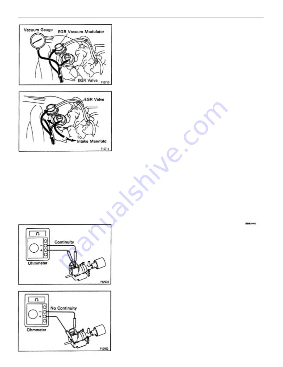
VSV INSPECTION

1. REMOVE VSV
2. INSPECT VSV
A. Inspect VSV for open circuit
Using an ohmmeter, check that there is continuity
between the terminals.
Resistance:

33 – 39 


at 20

C (68

F)

If there is no continuity, replace the VSV.
B. Inspect VSV for ground
Using an ohmmeter, check that there is no continuity
between each terminal and the body.
!f there is continuity, replace the VSV.

(c) Reconnect the vacuum hoses to their proper loca–
tions.
IF NO PROBLEM IS FOUND DURING THIS
INSPECTION, SYSTEM IS NORMAL; OTHERWISE
INSPECT EACH PART

9. INSPECT EGR VALVE
(a) Apply vacuum directly to the EGR valve with the
engine idle.
(b) Check that the engine runs rough or dies.

8. REMOVE VACUUM GAUGE
Remove the vacuum gauge, and reconnect the
vacuum hoses to their proper locations.

1MZ–FE ENGINE

EMISSION CONTROL SYSTEMS

EG2–209

Summary of Contents for 1 MZ-FE

Page 1: ...1MZ FE ENGINE 1MZ FE ENGINE EG2 1 ...

Page 2: ...DESCRIPTION The 1 MZ FE engine is a V 6 3 0 liter 24 valve DOHC engine ENGINE MECHANICAL OPERATION 1MZ FE ENGINE ENGINE MECHANICAL EG2 2 ...

Page 3: ...o 1 above and below the engine RH mounting bracket Pistons are made of high temperature resistant aluminum alloy and a depression is built into the piston head to prevent interference with the valves Piston pins are the full floating type with the pins fastened to neither the piston boss nor the connecting rods Instead snap rings are fitted on both ends of the pins preventing the pins from falling...

Page 4: ... 46011 Crankshaft Front Oil Seal Replacer 09248 55040 Valve Clearance Adjust Tool set Crankshaft pulley Crankshaft timing pulley 09213 54015 Crankshaft Pulley Holding Tool 09223 15030 Oil Seal Bearing Replacer 09201 41020 Valve Stem Oil Seal Replacer 09202 70010 Valve Spring Compressor 08223 00010 Cover Seal Replacer Crankshaft timing pulley Crankshaft front oil seal Crankshaft rear oil seal 1MZ F...

Page 5: ... Valve guide bushing 09631 22020 Power Steering Hose Nut 14 x 17 mm Wrench Set Spark plug tube gasket Camshaft timing pulley 09330 00021 Companion Flange Holding Tool 09816 30010 Oil Pressure Switch Socket 09249 63010 Torque Wrench Adaptor 09960 10010 Variable Pin Wrench Set 09843 18020 Diagnosis Check Wire Knock sensor Oil pressure switch RH camshaft timing pulley Crankshaft pulley 1MZ FE ENGINE ...

Page 6: ... Adjust Kit 09258 00030 Hose Plug set 09904 00010 Expander Set Precision straight edge Engine tune up tester Piston ring compressor Connecting rod aligner Piston ring expander EQUIPMENT For suspending engine Magnetic finger Cylinder gauge Caliper gauge Dye penetrant CO HC meter Dial indicator Micrometer Plastigage Heater 1MZ FE ENGINE FE ENGINE ENGINE MECHANICAL EG2 6 ...

Page 7: ...l pan No 2 oil pan Camshaft bearing cap Semi circular plug Spark plug tube Cylinder head cover 4 7 liters 5 0 US qts 4 1 Imp qts 4 5 liters 4 8 US qts 4 0 Imp qts Engine coolant drain cock Water seal plate Water inlet housing 08826 00080 Seal packing or equivalent 08826 00080 Seal packing or equivalent 5 5 liters 5 8 US qts 4 8 Imp qts 8 7 liters 9 2 US qts 7 7 Imp qts LUBRICANT Drive plate bolt T...

Page 8: ... is recommended NOTICE Do not use an alcohol type coolant The coolant should be mixed with demineralized water or distilled water TUNE UP ENGINE COOLANT INSPECTION 1 CHECK ENGINE COOLANT LEVEL AT RESERVOIR TANK The engine coolant level should be between the LOW and FULL lines If low check for leaks and add engine coolant up to the FULL line 2 CHECK ENGINE COOLANT QUALITY a Remove the radiator cap ...

Page 9: ...tion with SAE 5W 30 being the preferred engine oil Drain and refill capacity w Oil filter change 4 7 liters 5 0 US qts 4 1 Imp qts w o Oil filter change 4 5 liters 4 8 US qts 4 0 Imp qts 2 CHECK ENGINE OIL LEVEL The oil level should be between the L and F marks on the dipstick If low check for leakage and add oil up to the F mark NOTICE Do not fill with engine oil above the F mark Install the oil ...

Page 10: ...rge If the vehicle has been running wait 5 minutes or more after the vehicle stops before measuring the battery voltage If the voltage is less than specification charge the battery HINT Check the indicator as shown in the illustration BATTERY INSPECTION 1 Except Delco Battery CHECK BATTERY ELECTROLYTE LEVEL Check the electrolyte quantity of each cell A Maintenance Free Battery If under the lower l...

Page 11: ...ble link and fuses for continuity B Except Maintenance Free Battery Check the specific gravity of each cell Standard specific gravity 55D23L battery for GNB Incorporated 1 25 1 27 at 20 C 60 F 5513231 battery for JOHNSON CONTROLS 1 26 1 28 at 27 C 81 F 80D26L battery for GNB Incorporated 1 27 1 29 at 20 C 68 F 80D26L battery for JOHNSON CONTROLS 1 28 1 30 at 27 C 80 F If the gravity is less than s...

Page 12: ...t which has been used less than 5 minutes on a running engine Used belt refers to a belt which has been used on a running engine for 5 minutes or more After installing the belt check that it fits properly in the ribbed grooves Check by hand to confirm that the belt has not slipped out of the groove on the bottom of the pulley After installing a new belt run the engine for about 5 minutes and reche...

Page 13: ...7 REMOVE V BANK COVER Using a 5 mm hexagon wrench remove the 2 nuts and V bank cover 1 DISCONNECT NEGATIVE TERMINAL CABLE TO BATTERY CAUTION Work must be started after 90 seconds from the time the ignition switch is turned to the LOCK position and the negative terminal cable is discon nected from the battery 2 DRAIN ENGINE COOLANT 3 DISCONNECT RADIATOR INLET HOSE VALVE CLEARANCE INSPECTION AND ADJ...

Page 14: ...uum modulator 6 Vacuum hose from EGR valve 9 REMOVE AIR INTAKE CHAMBER a Disconnect the following hoses 1 Brake booster vacuum hose 2 PCV hose 3 Intake air control valve vacuum hose b Disconnect the data link connector 1 c Remove the nut and disconnect the 2 ground straps b Disconnect the following connectors 1 Intake air control valve connector 2 Fuel pressure connector 3 EGR VSV connector c Remo...

Page 15: ...trap f Disconnect the RH oxygen sensor connector clamp from the PS pressure tube g Remove the 2 nuts and disconnect the PS pressure tube h Disconnect the 2 PS air hoses i Remove the 2 bolts and No 1 engine hanger j Remove the 2 bolts and air intake chamber stay k Remove the 4 nuts EGR pipe and 2 gaskets 1MZ FE ENGINE ENGINE MECHANICAL EG2 15 ...

Page 16: ...or m Disconnect the following vacuum hoses 1 2 vacuum hoses from TVV 2 Vacuum hose from cylinder head rear plate o Using an 8 mm hexagon wrench remove the 2 bolts 2 nuts air intake chamber and gasket n Disconnect the following hoses 1 2 water bypass hoses 2 Air assist hose 3 Vacuum hose from charcoal canister 1MZ FE ENGINE FE ENGINE ENGINE MECHANICAL EG2 16 ...

Page 17: ...E FROM ENGINE LH SIDE a Disconnect the following connectors 1 3 injector connectors 2 3 ignition coil connectors b Remove the 2 nuts and disconnect the engine wire 11 DISCONNECT ENGINE WIRE FROM NO 3 TIMING BELT COVER Remove the bolt and 3 clamps and disconnect the engine wire 12 DISCONNECT ENGINE WIRE FROM ENGINE REAR SIDE Remove the 2 nuts and disconnect the engine wire 1MZ FE ENGINE ENGINE MECH...

Page 18: ...kshaft 1 revolution 360 and align the mark as above 16 REMOVE CYLINDER HEAD COVERS Remove the 8 bolts cylinder head cover and gasket Remove the 2 cylinder head covers 14 REMOVE IGNITION COILS Remove the 6 bolts and 6 ignition coils from the RH and LH cylinder heads 15 REMOVE SPARK PLUGS Using a 16 mm plug wrench remove the 6 spark plugs from the RH and LH cylinder heads HINT Arrange the ignition c...

Page 19: ...on valve clearance mea surements They will be used later to determine the required replacement adjusting shim Valve clearance Cold Intake 0 15 0 25 mm 0 006 0 010 in Exhaust 0 25 0 35 mm 0 010 0 014 in b Turn the crankshaft 2 3 of a revolution 240 and check only the valves indicated in the illustration Measure the valve clearance See procedure step a 1MZ FE ENGINE ENGINE MECHANICAL EG2 19 ...

Page 20: ...im To prevent it from being stuck insert it gently from the intake side at a slight angle 19 ADJUST VALVE CLEARANCE a Remove the adjusting shim Turn the camshaft so that the cam lobe for the valve to be adjusted faces up Turn the valve lifter with a screwdriver so that the notches would be perpendicular to the cam shaft c Turn the crankshaft a further 2 3 of a revolution 240 and check only the val...

Page 21: ...ust N T A 0 30 mm 0 012 in Select a new shim with a thickness as close as possible to the calculated values HINT Shims are available in 17 sizes in increments of 0 050 mm 0 0020 in from 2 500 mm 0 0984 in to 3 300 mm 0 1299 in c Install a new adjusting shim Place a new adjusting shim on the valve lifter with imprinted numbers facing down Press down the valve lifter with SST A and remove SST B SST ...

Page 22: ...Adjusting Shim Selection Chart Intake 1MZ FE ENGINE ENGINE MECHANICAL EG2 22 ...

Page 23: ...Adjusting Shim Selection Chart Exhaust 1MZ FE ENGINE ENGINE MECHANICAL EG2 23 ...

Page 24: ...R HEAD COVERS a Apply seal packing to the cylinder heads as shown in the illustration Seal packing Part No 08826 00080 or equivalent 22 REINSTALL IGNITION COILS Install the6 ignition coils to the RH and LH cylinder heads Torque 8 N m 80 kgf cm 69 in lbf 21 REINSTALL SPARK PLUGS Using a 16 mm plug wrench install the 6 spark plugs to the RH and LH cylinder heads Torque 18 N m 180 kgf cm 13 ft lbf 1M...

Page 25: ...E WIRE TO ENGINE LH SIDE a Connect the engine wire with the 2 nuts b Connect the following connectors 1 3 injector connectors 2 3 ignition coil connectors 26 RECONNECT ENGINE WIRE TO NO 3 TIMING BELT COVER a Connect the 3 clamps b Connect the engine wire with the bolt 24 RECONNECT ENGINE WIRE TO ENGINE REAR SIDE Connect the engine wire with the 2 nuts 1MZ FE ENGINE ENGINE MECHANICAL EG2 25 ...

Page 26: ...R a Using an 8 mm hexagon wrench install a new gasket and the air intake chamber with the 2 bolts and 2 nuts Torque 43 N m 440 kgf cm 32 ft lbf c Connect the following vacuum hoses 1 2 vacuum hoses to TVV 2 Vacuum hose to cylinder head rear plate b Connect the following hoses 1 2 water bypass hoses 2 Air assist hose 3 Vacuum hose to charcoal canister 1MZ FE ENGINE ENGINE MECHANICAL EG2 26 ...

Page 27: ...e bolt f install the No 1 engine hanger with the 2 bolts Torque 39 N m 400 kgf cm 19 ft lbf g Install the air intake chamber stay with the 2 bolts Torque 19 5 N m 200 kgf cm 14 ft lbf e Install 2 new gaskets and EGR pipe with the 4 nuts Torque 12 N m 120 kgf cm 9 ft lbf h Connect the 2 PS air hoses i Connect the PS pressure tube with the 2 nuts 1MZ FE ENGINE ENGINE MECHANICAL EG2 27 ...

Page 28: ...vacuum hose 2 PCV hose 3 Intake air control valve vacuum hose n Connect the data link connector 1 o Connect the 2 ground straps with the nut 28 REINSTALL V BANK COVER Using a 5 mm hexagon wrench install the V bank cover with the 2 nuts 28 REINSTALL EMISSION CONTROL VALVE SET a Install the emission control valve set with the 2 bolts Torque 8 N m 80 kgf cm 69 in lbf b Connect the following connector...

Page 29: ...r cleaner hose clamp bolt c Connect the PCV hose d Connect the accelerator cable clamp e Connect the volume air flow meter connector and wire clamp 33 FILL WITH ENGINE COOLANT Capacity 8 7 liters 9 2 US qts 7 7 Imp qts 34 RECONNECT NEGATIVE TERMINAL CABLE TO BATTERY 30 RECONNECT THROTTLE CABLE 31 RECONNECT ACCELERATOR CABLE 32 RECONNECT RADIATOR INLET HOSE 1MZ FE ENGINE ENGINE MECHANICAL EG2 29 ...

Page 30: ...u confirm the compatibility of your unit before use 3 CONNECT TIMING LIGHT TO ENGINE a Using a 5 mm hexagon wrench remove the 2 cap nuts and V bank cover IGNITION TIMING INSPECTION 1 WARM UP ENGINE Allow the engine to warm up to normal operating temperature b Connect the timing light pickup clip to the the green lead wire for the No 4 ignition coil HINT Use a timing light that can detect the prima...

Page 31: ... and E2 of the throttle position sensor Valve timing c Remove the SST from the data link connector 1 SST 09843 18020 6 FURTHER CHECK IGNITION TIMING Ignition timing 7 17 BTDC idle Transmission in neutral position HINT The timing mark moves in a range between 7 and 17 5 INSPECT IGNITION TIMING a Using SST connect terminals TE1 and E1 of the data link connector 1 SST 09843 18020 b Check the idle spe...

Page 32: ...ONNECT TIMING LIGHT FROM ENGINE a Remove the timing light b Using a 5 mm hexagon wrench install the V bank cover with the 2 cap nuts 8 DISCONNECT TACHOMETER FROM ENGINE 1MZ FE ENGINE ENGINE MECHANICAL EG2 32 ...

Page 33: ... for approx 90 seconds 1 INITIAL CONDITIONS a Engine at normal operating temperature b Air cleaner installed c All pipes and hoses of air induction system connected d All accessories switched OFF e All vacuum lines properly connected HINT All vacuum hoses for EGR system etc should be properly connected f SFI system wiring connectors fully plugged g Ignition timing set correctly h Transmission in n...

Page 34: ...eutral position i Tachometer and CO HC meter calibrated by hand 4 INSERT CO NC METER TESTING PROBE AT LEAST 40 cm 1 3 ft INTO TAILPIPE DURING IDLING 5 IMMEDIATELY CHECK CO HC CONCENTRATION AT IDLE AND OR 2 500 RPM HINT When performing the 2 mode 2 500 rpm and idle test follow the measurement order prescribed by the applicable local regulations IDLE AND OR 2500 RPM CO HC CHECK HINT This check is us...

Page 35: ...ce 3 Leaky EGR valve 4 Leaky intake and exhaust valves 5 Leaky cylinder 1 Restricted air filter 2 Faulty SFI systems Faulty fuel pressure regulator Clogged fuel return line Defective ECT switch Faulty ECM Faulty injector Faulty throttle position sensor Faulty volume air flow meter 1 Vacuum leaks PCV hose EGR valve Intake manifold Air intake chamber Throttle body IAC valve Brake booster line 2 Lean...

Page 36: ... remove the 2 cap nuts and V bank cover 3 REMOVE IGNITION COILS a Disconnect the 6 connectors from the RH and LH cylinder heads 1 WARM UP AND STOP ENGINE Allow the engine to warm up to normal operating temperature b Remove the 6 bolts and 6 ignition coils from the RH and LH cylinder heads HINT Arrange the ignition coils in the correct order 1MZ FE ENGINE ENGINE MECHANICAL EG2 36 ...

Page 37: ... is likely that the piston rings and or cylinder bore are worn or damaged If pressure stays low a valve may be sticking or seating is improper or there may be leakage past the gasket 5 CHECK CYLINDER COMPRESSION PRESSURE a Insert a compression gauge into the spark plug hole b Fully open the throttle c While cranking the engine measure the compression pressure HINT Always use a fully charged batter...

Page 38: ...o the RH and LH cylinder heads with the 6 bolts Torque 8 N m 80 kgf cm 69 in lbf 8 REINSTALL V BANK COVER Using a 5 mm hexagon wrench install the V bank cover with the 2 cap nuts b Connect the 6 ignition coil connectors 1MZ FE ENGINE ENGINE MECHANICAL EG2 38 ...

Page 39: ...TIMING BELT COMPONENTS FOR REMOVAL AND INSTALLATION 1MZ FE ENGINE ENGINE MECHANICAL EG2 39 ...

Page 40: ... 1MZ FE ENGINE ENGINE MECHANICAL EG2 40 ...

Page 41: ...n nected from the battery 2 REMOVE ENGINE COOLANT RESERVOIR TANK a Disconnect the reservoir hose 3 REMOVE GENERATOR DRIVE BELT Loosen the pivot bolt and adjusting lock bolt and remove the drive belt 4 REMOVE RH FRONT WHEEL 5 REMOVE RH FENDER APRON SEAL b Using a screwdriver remove the reservoir tank See Components for Removal and Installation TIMING BELT REMOVAL 1MZ FE ENGINE ENGINE MECHANICAL EG2...

Page 42: ...EMOVE NO 2 GENERATOR BRACKET a Loosen the generator pivot bolt b Remove the nut and bracket 8 REMOVE RH ENGINE MOUNTING STAY Remove the 3 bolts and RH engine mounting stay 6 REMOVE PS DRIVE BELT Loosen the 2 bolts and remove the drive belt 7 DISCONNECT GROUND STRAPS Disconnect the 2 straps 1MZ FE ENGINE ENGINE MECHANICAL EG2 42 ...

Page 43: ...the clamp 11 REMOVE CRANKSHAFT PULLEY a Using SST remove the pulley bolt SST 09213 54016 09330 00021 14 REMOVE N0 2 TIMING BELT COVER Remove the 5 bolts and timing belt cover 12 REMOVE No 1 TIMING BELT COVER Remove the 4 bolts and timing belt cover b Using SST remove the pulley SST 09213 00060 1MZ FE ENGINE ENGINE MECHANICAL EG2 43 ...

Page 44: ... pump alignment mark NOTICE Always turn the crankshaft clockwise c Check that timing marks of the camshaft timing pul leys and No 3 timing belt cover are aligned If not turn the crankshaft 1 revolution 360 d Remove the crankshaft pulley bolt 15 REMOVE ENGINE RH MOUNTING BRACKET Remove the 2 bolts nut and mounting bracket 16 REMOVE TIMING BELT GUIDE 1MZ FE ENGINE ENGINE MECHANICAL EG2 44 ...

Page 45: ... marks on the timing belt to the following position Timing mark of RH camshaft timing pulley Timing mark of LH camshaft timing pulley Dot mark of crankshaft timing pulley 21 REMOVE CAMSHAFT TIMING PULLEYS a Using SST remove the bolt and RH timing pulley SST 09249 63010 09960 10010 09962 01000 19 REMOVE TIMING BELT TENSIONER Alternately loosen the 2 bolts and remove them the tensioner and dust boot...

Page 46: ...er HINT Arrange the camshaft timing pulleys RH and LH sides 24 REMOVE CRANKSHAFT TIMING PULLEY a Remove the bolt and timing belt plate b Using SST remove the LH timing pulley SST 09960 10010 09962 01000 22 REMOVE NO 2 IDLER PULLEY Remove the bolt and idler pulley 1MZ FE ENGINE ENGINE MECHANICAL EG2 46 ...

Page 47: ...parting Check for proper installation Check the timing cover gasket for damage and proper installation b Using SST remove the crankshaft timing pulley SST 09213 60017 09213 00020 09213 00030 09213 00050 NOTICE Do not scratch the sensor part of the crankshaft timing pulley c If there is noticeable wear or cracks on the belt face check to see if there are nicks on the side of the idler pulley lock a...

Page 48: ...sh rod side the tensioner is all right If leakage is found replace the tensioner b Hold the tensioner with both hands and push the push rod strongly as shown to check that it doesn t move If the push rod moves replace the tensioner NOTICE Never hold the tensioner push rod facing down ward 2 INSPECT IDLER PULLEYS Check that the idler pulley turns smoothly If necessary replace the idler pulley d If ...

Page 49: ...the sensor part of the crankshaft timing pulley c Install the timing belt plate with the bolt Torque 8 N m 80 kgf cm 69 in lbf c Measure the protrusion of the push rod from the housing end Protrusion 10 0 10 8 mm 0 394 0 425 In If the protrusion is not as specified replace the tensi oner 2 INSTALL NO 1 IDLER PULLEY a Using a 10 mm hexagon wrench install the idler pulley with the plate washer and b...

Page 50: ...nch with a fulcrum length of 340 mm 113 39 in 5 INSTALL LH CAMSHAFT TIMING PULLEY a Install the timing pulley facing the flange side inward b Align the knock pin hole of the camshaft with the knock pin groove of the timing pulley as shown 3 INSTALL No 2 IDLER PULLEY a Install the idler pulley with the bolt Torque 43 N m 440 kgf cm 32 ft lbf b Check that the idler pulley moves smoothly d Using SST ...

Page 51: ...3 timing belt cover SST 09960 10010 09962 01000 c LH Camshaft Timing Pulley Position Using SST turn the camshaft pulley align the timing marks of the camshaft and the No 3 timing belt cover SST 09960 10010 09962 01000 6 SET NO 1 CYLINDER TO TDC COMPRESSION a Crankshaft Timing Pulley Position Temporarily install the crankshaft pulley bolt to the crankshaft Turn the crankshaft and align the cranksha...

Page 52: ... Release the press 10 CHECK VALVE TIMING a Turn the crankshaft and align the crankshaft timing pulley groove with the oil pump alignment mark NOTICE Always turn the crankshaft clockwise 9 INSTALL TIMING BELT TENSIONER a Temporarily install the tensioner with the 2 bolts b Alternately tighten the 2 bolts Torque 27 N m 280 kgf cm 20 ft lbf c Remove the 1 27 mm hexagon wrench from the tensi oner d In...

Page 53: ...lustration 4 After installing the gasket press down on it sc that the adhesive firmly sticks to the belt cover b Install new gasket to the No 2 belt cover b Check that the timing marks of the RH and LH timing pulleys with the timing marks of the No 3 timing belt cover as shown in the illustration If the marks do not align remove the timing belt and reinstall it c Remove the crankshaft pulley bolt ...

Page 54: ...asket evenly to the part of the belt cover shaded back in the illustration NOTICE When joining 2 gaskets do not leave a gap between them Cut off any excess gasket 4 After installing the gasket press down on it so that the adhesive firmly sticks to the belt cover b Install new gaskets to the No 1 belt cover 14 CONNECT ENGINE WIRE a Connect the engine wire with the clamp b Install the bolt holding t...

Page 55: ...E MOVING CONTROL ROD Install the mounting bracket and control rod with the 3 bolts Torque 63 7 N m 650 kgf cm 47 ft lbf 17 INSTALL NO 2 GENERATOR BRACKET Install the bracket with the pivot bolt and nut Do not tighten the bolt yet Torque 28 N m 290 kgf cm 21 ft lbf for Nut 19 INSTALL RH ENGINE MOUNTING STAY Install the mounting stay with the 3 bolts Torque 31 4 N m 320 kgf cm 23 ft lbf 24 CONNECT G...

Page 56: ...GENERATOR DRIVE BELT Adjust the drive belt See CH section Drive belt tension New belt 175 5 lbf Used belt 115 20 lbf 23 INSTALL COOLANT RESERVOIR TANK 24 CONNECT NEGATIVE TERMINAL CABLE TO BATTERY 25 START ENGINE AND CHECK FOR ABNORMAL NOISE AND SMOOTH OPERATION 26 INSTALL RH FENDER APRON SEAL 27 INSTALL RH FRONT WHEEL 1MZ FE ENGINE FE ENGINE ENGINE MECHANICAL EG2 56 ...

Page 57: ...CYLINDER HEAD COMPONENTS FOR REMOVAL AND INSTALLATION 1MZ FE ENGINE ENGINE MECHANICAL EG2 57 ...

Page 58: ... 1MZ FE ENGINE ENGINE MECHANICAL EG2 58 ...

Page 59: ... 1MZ FE ENGINE ENGINE MECHANICAL EG2 59 ...

Page 60: ... 1MZ FE ENGINE ENGINE MECHANICAL EG2 60 ...

Page 61: ... 1MZ FE ENGINE ENGINE MECHANICAL EG2 61 ...

Page 62: ...CONTROL ACTUATOR a Remove the bolt clip and actuator cover b Disconnect the actuator connector and clamp c Remove the 3 bolts and disconnect the actuator with the bracket CYLINDER HEADS REMOVAL See Components for Removal and Installation 1 REMOVE BATTERY AND TRAY CAUTION Work must be started after 90 seconds from the time the ignition switch is turned to the LOCK position and the negative terminal...

Page 63: ...inlet 11 DISCONNECT FUEL HOSES Disconnect the fuel inlet and return hoses CAUTION Catch leaking fuel in a container 8 REMOVE RH ENGINE MOUNTING STAY Remove the 3 bolts and RH engine mounting stay 10 DISCONNECT HEATER HOSES Disconnect the 2 hoses 9 DISCONNECT RADIATOR HOSES 1MZ FE ENGINE ENGINE MECHANICAL EG2 63 ...

Page 64: ...MOVE AIR INTAKE CHAMBER a Disconnect the following hoses 1 Brake booster vacuum hose 2 PCV hose 3 Intake air control valve vacuum hose b Disconnect the data link connector 1 c Remove the nut and disconnect the 2 ground straps b Disconnect the following connectors 1 Intake air control valve connector 2 Fuel pressure connector 3 EGR VSV connector 13 REMOVE V BANK COVER Using a 5 mm hexagon wrench re...

Page 65: ...f Disconnect the RH oxygen sensor connector clamp from the PS pressure tube g Remove the 2 nuts and disconnect the PS pressure tube h Disconnect the 2 PS air hoses i Remove the 2 bolts and No 1 engine hanger j Remove the 2 bolts and air intake chamber stay k Remove the 4 nuts EGR pipe and 2 gaskets 1MZ FE ENGINE FE ENGINE ENGINE MECHANICAL EG2 65 ...

Page 66: ...nnector m Disconnect the following vacuum hoses 1 2 vacuum hoses from TVV 2 Vacuum hose from cylinder head rear plate o Using an 8 mm hexagon wrench remove the 2 bolts 2 nuts air intake chamber and gasket n Disconnect the following hoses 1 2 water bypass hoses 2 Air assist hose 3 Vacuum hose from charcoal canister 1MZ FE ENGINE ENGINE MECHANICAL EG2 66 ...

Page 67: ...rt of EGR vacuum modu lator 2 Vacuum hose from R port of EGR vacuum modu lator b Remove the 2 bolts 2 nuts throttle body and gasket 20 DISCONNECT ENGINE WIRE FROM ENGINE LH SIDE a Disconnect the following connectors 1 3 injector connectors 2 3 ignition coil connectors b Remove the 2 nuts and disconnect the engine wire 19 REMOVE EGR VALVE AND VACUUM MODULATOR FROM AIR INTAKE CHAMBER Remove the 3 nu...

Page 68: ...connector b Remove the 5 nuts and disconnect the engine wire 22 DISCONNECT ENGINE WIRE FROM ENGINE REAR SIDE a Disconnect the following connectors 1 LH oxygen sensor 2 Engine coolant temperature sensor 3 Camshaft position sensor b Disconnect the 3 clamps c Remove the 2 nuts and disconnect the engine wire 21 DISCONNECT ENGINE WIRE FROM NO 3 TIMING BELT COVER Disconnect the 2 clamps and engine wire ...

Page 69: ...olds e Remove the front exhaust pipe and gaskets 25 REMOVE SPARK PLUGS Using a 16 mm plug wrench remove the6 spark plugs from the RH and LH cylinder heads 24 REMOVE IGNITION COILS Remove the6 bolts and6 ignition coils from the RH and LH cylinder heads 26 REMOVE FRONT EXHAUST PIPE a Remove the 2 bolts and front exhaust pipe clamp HINT Arrange the ignition coils in the correct order 1MZ FE ENGINE EN...

Page 70: ... 10010 09862 01000 HINT Arrange the camshaft timing pulleys RH and LH sides 27 REMOVE TIMING BELT See steps 2 to 20 on pages EG2 41 to 45 b Using SST remove the LH timing pulley SST 09960 10010 09962 01000 29 REMOVE NO 2 IDLER PULLEY Remove the bolt and idler pulley 1MZ FE ENGINE ENGINE MECHANICAL EG2 70 ...

Page 71: ...NDER HEAD REAR PLATE a Disconnect the vacuum hose from the vacuum tank b Remove the nut and disconnect the ground strap c Remove the bolt and rear plate 32 REMOVE WATER INLET PIPE a Remove the bolt and inlet pipe b Remove the O ring 30 REMOVE NO 3 TIMING BELT COVER Remove the 6 bolts and belt cover 33 REMOVE AIR ASSIST HOSE AND VACUUM HOSE 1MZ FE ENGINE ENGINE MECHANICAL EG2 71 ...

Page 72: ...d 35 REMOVE FUEL PRESSURE REGULATOR FROM LH DELIVERY PIPE a Remove the 2 bolts and pull out the pressure regula tor b Remove the 0 ring from the pressure regulator 37 REMOVE FUEL PULSATION DAMPER AND No 1 FUEL PIPE Remove the bolt pulsation damper No 1 fuel pipe and 2 gaskets 38 REMOVE No 2 FUEL PIPE Remove the 2 union bolts No 2 fuel pipe and 4 gas kets 36 REMOVE TVV FROM INTAKE MANIFOLD 1MZ FE E...

Page 73: ...e manifold gaskets 42 REMOVE LH EXHAUST MANIFOLD a Remove the main heated oxygen sensor Bank 2 Sensor 1 c Pull out the 6 injectors from the delivery pipes Remove the 0 ring and grommet from each injector 41 REMOVE No 2 ENGINE HANGER Remove the 2 bolts and engine hanger b Remove the bolt nut and exhaust manifold stay 1MZ FE ENGINE ENGINE MECHANICAL EG2 73 ...

Page 74: ...h the dipstick from the No 1 oil pan c Remove 0 ring from the dipstick guide 45 REMOVE RH EXHAUST MANIFOLD a Remove the main heated oxygen sensor Bank 1 Sensor 1 44 REMOVE PS BRACKET Remove the 3 bolts and PS bracket c Remove the 6 nuts exhaust manifold and gasket b Remove the 4 nuts EGR pipe and 2 gaskets 1MZ FE ENGINE ENGINE MECHANICAL EG2 74 ...

Page 75: ...haft to seize or break To avoid this the following steps should be carried out 46 REMOVE CYLINDER HEAD COVERS Remove the 8 bolts cylinder head cover and gasket Remove the 2 cylinder head covers 47 REMOVE CAMSHAFT POSITION SENSOR a Remove the bolt and position sensor b Remove the gasket from the position sensor c Remove the bolts 2 nuts exhaust manifold stay and exhaust manifold plate d Remove the ...

Page 76: ...several passes in the sequence shown b Remove the 5 bearing caps oil seal and exhaust cam shaft A Remove intake camshaft of RH cylinder head a Align the timing marks 2 dot marks of the camshaft drive and driven gears by turning the camshaft with a wrench C Remove intake camshaft of LH cylinder head a Align the timing marks 11 dot mark of the camshaft drive and driven gears by turning the camshaft ...

Page 77: ...e operation D Remove exhaust camshaft of LH cylinder head a Uniformly loosen and remove the 10 bearing cap bolts in several passes in the sequence shown b Remove the 5 bearing caps oil seal and exhaust cam shaft c Uniformly loosen and remove the 10 bearing cap bolts in several passes in the sequence shown d Remove the 5 bearing caps and intake camshaft HINT Arrange the camshafts in the correct ord...

Page 78: ...ft b Using SST turn the sub gear counterclockwise and remove the service bolt SST 09960 10010 09962 0100 d Remove the following parts 1 Wave washer 2 Camshaft sub gear 3 Camshaft gear spring HINT Arrange the camshaft sub gears and gear spr ings RH and LH sides c Using snap ring pliers remove the snap ring 1MZ FE ENGINE ENGINE MECHANICAL EG2 78 ...

Page 79: ...d cylinder block b Uniformly loosen and remove the 8 cylinder head 12 pointed head bolts on each cylinder head in several passes in the sequence shown then repeat for the other side as shown Remove the 16 cylinder head bolts and plate washers NOTICE Head warpage or cracking could result from removing bolts in an incorrect order 50 REMOVE CYLINDER HEADS a Using a 8 mm hexagon wrench remove the cyli...

Page 80: ...D DISASSEMBLY See Components for Removal and Installation b Remove the following parts 1 Spring retainer 2 Valve spring 3 Valve HINT Arrange the valve lifters and shims in the cor rect order c Using needle nose pliers remove the oil seal 1 REMOVE VALVE LIFTERS AND SHIMS 1MZ FE ENGINE ENGINE MECHANICAL EG2 80 ...

Page 81: ...ressed air blow carbon and oil from the bolt holes CAUTION Protect your eyes when using high pressure compressed air 2 CLEAN CYLINDER HEAD A Remove gasket material Using a gasket scraper remove all the gasket material from the cylinder block contact surface NOTICE Be careful not to scratch the cylinder block contact surface d Using compressed air and a magnetic finger remove the spring seat by blo...

Page 82: ...than maximum replace the cylin der head B Clean combustion chambers Using a wire brush remove all the carbon from the combustion chambers NOTICE Be careful not to scratch the cylinder block contact surface C Clean cylinder head Using a soft brush and solvent thoroughly clean the cylinder head D Clean valve guide bushings Using a valve guide bushing brush and solvent clean all the guide bushings 1M...

Page 83: ... 480 mm 0 2152 0 2157 in B Inspect for cracks Using a dye penetrant check the combustion cham ber intake ports exhaust ports and cylinder block surface for cracks If cracked replace the cylinder head 5 INSPECT VALVE STEMS AND GUIDE BUSHINGS a Using a caliper gauge measure the inside diameter of the guide bushing Bushing inside diameter 5 510 5 530 mm 0 2169 0 2177 in 4 CLEAN VALVES a Using a gaske...

Page 84: ...m 0 0031 in Exhaust 0 10 mm 0 0039 in If the clearance is greater than maximum replace the valve and guide bushing 6 IF NECESSARY REPLACE VALVE GUIDE BUSHINGS a Gradually heat the cylinder head to 80 100 C 176 212 F c Using a caliper gauge measure the bushing bore di ameter of the cylinder head b Using SST and a hammer tap out the guide bushing SST 09201 01055 09608 20012 09608 03020 Bushing bore ...

Page 85: ...Grind the valve enough to remove pits and carbon b Check that the valve is ground to the correct valve face angle Valve face angle 44 5 h Using a sharp 5 5 mm reamer ream the guide bushing to obtain the standard specified clearance See step 5 above between the guide bushing and valve stem e Gradually heat the cylinder head to 80 100 C 176 212 F HINT Different bushings are used for the intake and e...

Page 86: ...tandard margin thickness 1 0 mm 0 039 in Minimum margin thickness 0 5 mm 0 020 in If the margin thickness is less than minimum replace the valve e Check the surface of the valve stem tip for wear If the valve stem tip is worn resurface the tip with a grinder or replace the valve NOTICE Do not grind off more than minimum 8 INSPECT AND CLEAN VALVE SEATS a Using a 45 carbide cutter resurface the valv...

Page 87: ...he middle of the valve face with the following width 1 0 1 4 mm 0 039 0 055 In If not correct the valve seats as follows 1 If the seating is too high on the valve face use 30 and 45 cutters to correct the seat 9 INSPECT VALVE SPRINGS a Using a steel square measure the deviation of the valve spring Maximum deviation 2 0 mm 0 079 in If the deviation is greater than maximum replace the valve spring d...

Page 88: ... a dial indicator measure the circle runout at the center journal Maximum circle runout 0 06 mm 0 0024 in If the circle runout is greater than maximum replace the camshaft c Using a spring tester measure the tension of the valve spring at the specified installed length Installed tension 186 206 N 19 0 21 0 kgf 41 9 46 3 lbf at 33 8 mm 1 331 in If the installed tension is not as specified replace t...

Page 89: ...amshaft journals b Place the camshafts on the cylinder head c Lay a strip of Plastigage across each of the camshaft journals D Inspect camshaft bearings Check that bearings for flaking and scoring If the bearings are damaged replace the bearing caps and cylinder head as a set d Install the bearing caps See step 3 on pages EG2 98 to 102 Torque 16 N m 160 kgf cm 12 ft lbf NOTICE Do not turn the cams...

Page 90: ... moving the camshaft back and forth Standard thrust clearance 0 040 0 090 mm 0 0016 0 0035 in Maximum thrust clearance 0 12 mm 0 0047 in If the thrust clearance is greater than maximum re place the camshaft If necessary replace the bearing caps and cylinder head as a set c Remove the camshafts G Inspect camshaft gear backlash a Install the camshafts without installing the exhaust cam sub gear See ...

Page 91: ...oil clearance is greater than maximum replace the lifter If necessary replace the cylinder head H Inspect camshaft gear spring Using a vernier caliper measure the free distance between the spring ends Free distance 18 2 18 8 mm 0 712 0 740 in If the free distance is not as specified replace the gear spring 11 INSPECT VALVE LIFTERS AND LIFTER BORES a Using a caliper gauge measure the lifter bore di...

Page 92: ...ER HEAD BOLTS for 12 Pointed Head Bolts Using a caliper gauge measure the thread outside diameter of the bolt Standard outside diameter 8 95 9 05 mm 0 3524 0 3563 in Minimum outside diameter 8 75 mm 0 3445 in If the diameter is less than minimum replace the bolt 14 INSPECT EXHAUST MANIFOLD Using a precision straight edge and feeler gauge mea sure the surface contacting the cylinder head for war pa...

Page 93: ...sket lip f Return the ventilation plate tab to its original position 16 IF NECESSARY REPLACE SPARK PLUG TUBE GASKETS a Bend up the tab on the ventilation baffle plate which prevents the gasket from the slipping out b Using a screwdriver and hammer tap out the gasket HINT Thoroughly clean all parts to be assembled Before installing the parts apply new engine oil to all sliding and rotating surfaces...

Page 94: ... there is 42 4 43 4 mm 1 669 1 749 protruding from the camshaft bearing cap installation surface of the cylinder head NOTICE Avoid pressing a new spark plug tube In too far by measuring the amount of the protrusion while press ing b Install the following parts 1 Valve 2 Spring seat 3 Valve spring 4 Spring retainer 3 INSTALL VALVES a Using SST push in a new oil seal SST 09201 41020 HINT The intake ...

Page 95: ...heck that the valve lifter rotates smoothly by hand c Using SST compress the valve spring and place the 2 keepers around the valve stem SST 09202 70010 d Using a plastic faced hammer lightly tap the valve stem tip to ensure a proper fit 1MZ FE ENGINE ENGINE MECHANICAL EG2 95 ...

Page 96: ...n the threads and under the heads of the cylinder head bolts b Install and uniformly tighten the cylinder head bolts on each cylinder head in several passes in the se quence shown then repeat for the other side as shown Torque 64 N m 550 kgf cm 40 ft lbf If any of the cylinder head bolts does not meet the torque specification replace the cylinder head bolt d Retighten the cylinder head bolts by 90...

Page 97: ...ch cylinder head then repeat for the other side as shown Torque 18 5 N m 185 kgf cm 13 ft lbf 2 ASSEMBLY EXHAUST CAMSHAFTS a Mount the hexagonal wrench head portion of the camshaft in a vise NOTICE Be careful not to damage the camshaft b Install the following parts 1 Camshaft gear spring 2 Camshaft sub gear 3 Wave washer c Using snap ring pliers install the snap ring 1MZ FE ENGINE ENGINE MECHANICA...

Page 98: ...Using SST align the holes of the camshaft main gear and sub gear by turning camshaft sub gear coun terclockwise and install a service bolt SST 09960 10010 09962 0100 HINT Align the pins on the gears with the gear spring ends A Install exhaust camshaft of RH cylinder head a Apply new engine oil to the thrust portion and journal of the camshaft b Place the exhaust camshaft at 90 angle of timing mark...

Page 99: ...on the threads and under the heads of the bearing cap bolts i Install and uniformly tighten the 10 bearing cap bolts in several passes in the sequence shown Torque 16 N m 160 kgf cm 12 ft lbf e Remove any old packing FIPG material f Apply seal packing to the No 1 bearing cap as shown Seal packing Part No 08826 00080 or equivalent g Install the 5 bearing caps in their proper locations d Install the...

Page 100: ...dot mark on the cylinder head f Install and uniformly tighten the 10 bearing cap bolts in several passes in the sequence shown Torque 16 N m 160 kgf cm 12 ft Ibf e Apply a light coat of engine oil on the threads and under the heads of the bearing cap bolts c Apply MP grease to a new oil seal lip g Remove the service bolt 1MZ FE ENGINE ENGINE MECHANICAL EG2 100 ...

Page 101: ...n the threads and under the heads of the bearing cap bolts i Install and uniformly tighten the 10 bearing cap bolts in several passes in the sequence shown Torque 16 N m 160 kgf cm 12 ft lbf e Remove any old packing FIPG material f Apply seal packing to the No 1 bearing cap as shown Seal packing Part No 08826 00080 or equivalent g Install the 5 bearing caps in their proper locations d Install the ...

Page 102: ...ine oil on the threads and under the heads of bearing cap bolts f Install and uniformly tighten the 10 bearing cap bolts in several passes in the sequence shown Torque 16 N m 160 kgf cm 12 ft lbf 6 INSTALL SEMI CIRCULAR PLUGS a Remove any old packing FIPG material b Apply seal packing to the semi circular plug grooves Seal packing Part No 08826 00080 or equivalent d Install the 5 bearing caps in t...

Page 103: ... Seal packing Part No 08826 00080 or equivalent 6 INSTALL CAMSHAFT POSITION SENSOR a Install a new gasket to the position sensor b Install the positron sensor with the bolt Torque 8 N m 80 kgf cm 69 in lbf c Install the 4 semi circular plugs to the cylinder heads 1MZ FE ENGINE ENGINE MECHANICAL EG2 103 ...

Page 104: ...Install the cylinder head cover with the 8 bolts Uni formly tighten the bolts in several passes Install the 2 cylinder head covers Torque 8 N m 80 kgf cm 69 in lbf 8 INSTALL RH EXHAUST MANIFOLD a Install a new gasket and the exhaust manifold with the 6 nuts Torque 49 N m 500 kgf cm 36 ft lbf d Install the main heated oxygen sensor Bank 1 Sensor 1 Torque 44 N m 450 kgf cm 33 ft lbf c Install 2 new ...

Page 105: ...l the dipstick 11 INSTALL LH EXHAUST MANIFOLD a Install a new gasket and the exhaust manifold with the 6 nuts Torque 49 N m 500 kgf cm 36 ft lbf c Install the main heated oxygen sensor Bank 2 Sensor 1 Torque 44 N m 450 kgf cm 33 ft lbf b Install the exhaust main manifold stay with the bolt and nut Torque 19 5 N m 200 kgf cm 14 ft lbf 9 INSTALL PS BRACKET Install the PS bracket with the 3 bolts Tor...

Page 106: ... clockwise and counter clockwise push it to the delivery pipes Install the 6 injectors d Position the injector connector outward 14 INSTALL INJECTORS AND DELIVERY PIPES a Install 2 new grommets to each injector b Apply a light coat of gasoline to 2 new 0 rings and install them to each injector 12 INSTALL No 2 ENGINE HANGER Install the engine hanger with the 2 bolts Torque 19 5 N m 200 kgf cm 14 ft...

Page 107: ...ect installation of O rings Replace the O rings i Position the injector connector outward f Place the delivery pipes together with the 6 injectors in position on the intake manifold g Temporarily install the 4 bolts holding the delivery pipes to the intake manifold 15 INSTALL No 2 FUEL PIPE Install the No 2 fuel pipe with the 2 union bolts and 4 gaskets Torque 32 5 N m 330 kgf cm 24 ft lbf j Tight...

Page 108: ... the pressure regulator and repeat steps b and e above 17 INSTALL TVV a Apply adhesive to 2 or 3 threads Adhesive Part No 08833 00070 THREE BOND 1324 or equivalent 18 INSTALL FUEL PRESSURE REGULATOR a Apply a light coat of gasoline to a new 0 ring and install it to the pressure regulator b Install the TVV Torque 30 N m 305 kgf cm 22 ft lbf 1MZ FE ENGINE ENGINE MECHANICAL EG2 108 ...

Page 109: ...ETIGHTEN WATER OUTLET MOUNTING BOLTS AND NUTS Torque 15 N m 150 kgf cm 11 ft lbf 22 INSTALL WATER INLET PIPE a Install a new O ring to the water inlet pipe b Apply soapy water to the O ring d Install the pressure regulator with the 2 bolts Torque 8 N m 80 kgf cm 69 in lbf 21 INSTALL AIR ASSIST HOSE 1MZ FE ENGINE ENGINE MECHANICAL EG2 109 ...

Page 110: ...t leave a gap be tween them Cut off any excess gasket 4 After installing the gasket press down on it so that the adhesive firmly sticks to the belt cover b Install new gaskets to the No 3 belt cover 23 INSTALL CYLINDER HEAD REAR PLATE a Install the rear plate and grand strap with the bolt and nut Torque 8 N m 80 kgf cm 69 in lbf b Connect the vacuum hose to the air intake chamber c Connect the 2 v...

Page 111: ...ock pin groove of the timing pulley as shown 27 INSTALL LH CAMSHAFT TIMING PULLEY a Install the timing pulley facing the flange side inward b Align the knock pin hole of the camshaft with the knock pin groove of the timing pulley as shown 25 INSTALL NO 2 IDLER PULLEY a Install the idler pulley with the bolt Torque 43 N m 440 kgf cm 32 ft lbf b Check that the idler pulley moves smoothly d Using SST...

Page 112: ...pipe Torque 56 N m 570 kgf cm 41 ft lbf d Connect the bracket with the 2 bolts Torque 19 N m 195 kgf cm 14 ft lbf e Connect the front exhaust pipe clamp with the 2 bolts Torque 29 N m 300 kgf cm 22 ft lbf 31 INSTALL IGNITION COILS Install the6 ignition coils to the RH and LH cylinder heads Torque 8 N m 80 kgf cm 69 in lbf 30 INSTALL SPARK PLUGS Using a 16 mm plug wrench install the6 spark plugs to...

Page 113: ...gens sensor connector b Connect the engine wire with the 5 nuts 33 CONNECT ENGINE WIRE TO ENGINE REAR SIDE a Connect the following connectors 1 LH oxygen sensor 2 Engine coolant temperature sensor 3 Camshaft position sensor b Connect the 3 clamps c Connect the engine wire with the 2 nuts 34 CONNECT ENGINE WIRE TO N0 3 TIMING BELT COVER Connect the engine wire with the 2 clamps 1MZ FE ENGINE ENGINE...

Page 114: ...et the EGR valve and vacuum mod ulator with the 3 nuts Torque 12 N m 120 kgf cm 9 ft lbf 35 CONNECT ENGINE WIRE TO ENGINE LH SIDE a Connect the following connectors 1 3 injector connectors 2 3 ignition coil connectors b Connect the engine wire with the 2 nuts 38 INSTALL A C IDLE UP VSV TO AIR INTAKE CHAMBER a Install the A C idle up VSV with the 2 bolts b Connect the air hose 37 INSTALL THROTTLE B...

Page 115: ...e intake air control valve and data link con nector 1 clamp with the 3 nuts Torque 14 5 N m 145 kgf cm 10 ft lbf d Connect the A C air hose 40 INSTALL AIR INTAKE CHAMBER a Using an 8 mm hexagon wrench install a new gasket and the air intake chamber with the 2 bolts and 2 nuts Torque 43 N m 440 kgf cm 32 ft lbf c Connect the following vacuum hoses 1 2 vacuum hoses to TVV 2 Vacuum hose to cylinder h...

Page 116: ... with the 2 bolts Torque 39 N m 400 kgf cm 19 ft lbf g Install the air intake chamber stay with the 2 bolts Torque 19 5 N m 200 kgf cm 14 ft lbf e Install 2 new gaskets and EGR pipe with the 4 nuts Torque 12 N m 120 kgf cm 9 ft lbf h Connect the 2 PS air hoses i Connect the PS pressure tube with the 2 nuts 3 Vacuum hose to charcoal canister 1MZ FE ENGINE FE ENGINE ENGINE MECHANICAL EG2 116 ...

Page 117: ...n sensor connector clamp to the PS pressure tube k Connect the ground strap with the bolt 1 Connect the hydraulic pressure pipe to the air intake chamber with the bolt 41 INSTALL EMISSION CONTROL VALVE SET a Install the emission control valve set with the 2 bolts Torque 8 N m 80 kgf cm 69 in lbf b Connect the following connectors 1 Intake air control connector 2 Fuel pressure connector 3 EGR VSV c...

Page 118: ...r 6 Vacuum hose to EGR valve 44 CONNECT FUEL HOSES a Connect the fuel return hose to the fuel pipe b Connect the fuel inlet hose to the fuel filter Torque 30 N m 300 kgf cm 22 ft lbf 42 INSTALL V BANK COVER Using a 5 mm hexagon wrench install the V bank cover with the 2 nuts 43 CONNECT PRESSURE HOSE TO HYDRAULIC MOTOR Connect the pressure hose to the water inlet 45 CONNECT HEATER HOSES Connect the...

Page 119: ...lume air flow meter connector and wire clamp 49 w CRUISE CONTROL SYSTEM INSTALL CRUISE CONTROL ACTUATOR a Connect the actuator and bracket with the 3 bolts b Connect the actuator connector and clamp c Install the actuator cover with the bolt and clip 47 INSTALL RH ENGINE MOUNTING STAY Install the mounting stay with the 3 bolts Torque 31 4 N m 320 kgf cm 23 ft lbf 48 CONNECT GROUND STRAPS Connect t...

Page 120: ...ck slippage correct shift points and smooth operation 57 RECHECK ENGINE COOLANT LEVEL 53 FILL WITH ENGINE COOLANT Capacity 8 7 liters 9 2 US qts 7 7 Imp qts 51 CONNECT THROTTLE CABLE 52 CONNECT ACCELERATOR CABLE 54 INSTALL BATTERY TRAY AND BATTERY 1MZ FE ENGINE ENGINE MECHANICAL EG2 120 ...

Page 121: ...CYLINDER BLOCK COMPONENTS FOR ENGINE REMOVAL AND INSTALLATION 1MZ FE ENGINE ENGINE MECHANICAL EG2 121 ...

Page 122: ... 1MZ FE ENGINE ENGINE MECHANICAL EG2 122 ...

Page 123: ... 1MZ FE ENGINE ENGINE MECHANICAL EG2 123 ...

Page 124: ... 1 REMOVE BATTERY AND TRAY CAUTION Work must be started after 90 seconds from the time the ignition switch is turned to the LOCK position and the negative terminal cable is discon nected from the battery 2 REMOVE HOOD 3 DRAIN ENGINE COOLANT 4 DRAIN ENGINE OIL 5 DISCONNECT ACCELERATOR CABLE 6 DISCONNECT THROTTLE CABLE 8 w CRUISE CONTROL SYSTEM REMOVE CRUISE CONTROL ACTUATOR a Remove the bolt clip a...

Page 125: ...pron e Remove the bolt and disconnect the ground strap f Disconnect the wire clamp 11 DISCONNECT VACUUM HOSES Disconnect the following vacuum hoses 1 Vacuum hoses from vacuum tank for intake air control valve 2 2 igniter connectors 3 Noise filter connector 4 Connector from LH fender apron 5 2 ground straps c Disconnect the wire clamp 9 REMOVE RADIATOR See page EG2 336 1MZ FE ENGINE ENGINE MECHANIC...

Page 126: ... Catch leaking fuel in a container 3 Brake booster vacuum hose from air intake cha mber 14 DISCONNECT TRANSAXLE CONTROL CABLE FROM TRANSAXLE 12 DISCONNECT HEATER HOSES Disconnect the 2 hoses 2 Vacuum hose from charcoal canister 1MZ FE ENGINE FE ENGINE ENGINE MECHANICAL EG2 126 ...

Page 127: ...ctors 3 Cooling fan ECU connector 16 REMOVE A C COMPRESSOR WITHOUT DISCONNECTING HOSES a Disconnect the A C compressor connector b Remove the drive belt c Remove the 5 bolts and drive belt adjusting bar brack et and disconnect the A C compressor HINT Move the compressor aside and suspend it c Disconnect the wire clamp d Remove the 2 nuts and pull out the engine wire from the cowl panel 1MZ FE ENGI...

Page 128: ...REMOVE PS PUMP WITHOUT DISCONNECTING HOSES a Remove the PS drive belt b Remove the 2 bolts and disconnect the PS pump from the engine HINT Move the PS pump aside and suspend it 19 DISCONNECT PS PRESSURE TUBE a Disconnect the 2 PS air hoses b Remove the 2 nuts and disconnect the PS pressure tube 20 DISCONNECT HYDRAULIC COOLING FAN PRESSURE HOSE Using SST disconnect the pressure hose SST 09631 22020...

Page 129: ...NTING INSULATOR Remove the 4 bolts and disconnect the mounting insulator 24 REMOVE ENGINE MOUNTING SHOCK ABSORBER Remove the 4 bolts and engine mounting shock ab sorber 25 DISCONNECT FR ENGINE MOUNTING INSULATOR Remove the 3 bolts and disconnect the mounting insulator 26 ATTACH ENGINE SLING DEVICE TO ENGINE HANGERS 1MZ FE ENGINE ENGINE MECHANICAL EG2 129 ...

Page 130: ...nd mounting brack et 29 REMOVE RH ENGINE MOUNTING STAY Remove the 3 bolts and RH engine mounting stay 27 REMOVE COOLANT RESERVOIR TANK a Disconnect the reservoir hose 28 DISCONNECT GROUND STRAPS Disconnect the 2 straps b Using a screwdriver remove the reservoir tank 1MZ FE ENGINE ENGINE MECHANICAL EG2 130 ...

Page 131: ...ch b Make sure the engine is clear of all wiring hoses and cables c Place the engine and transaxle assembly onto the stand 32 REMOVE FR ENGINE MOUNTING INSULATOR Remove the 4 bolts and mounting insulator 33 REMOVE RR ENGINE MOUNTING INSULATOR Remove the 4 bolts and mounting insulator 34 REMOVE FRONT EXHAUST PIPE STAY Remove the 2 bolts and pipe stay 1MZ FE ENGINE ENGINE MECHANICAL EG2 131 ...

Page 132: ...meter 3 Starter 50 terminal 4 Starter B terminal 5 Speed sensor connector b Disconnect the 2 wire clamps from the transaxle ENGINE TRANSAXLE SEPARATION See Components for Engine Transaxle Separation and Assembly COMPONENTS FOR ENGINE TRANSAXLE SEPARATION AND ASSEMBLY 1MZ FE ENGINE ENGINE MECHANICAL EG2 132 ...

Page 133: ...nkshaft pulley bolt to gain access to each bolt c Hold the crankshaft pulley bolt with a wrench and remove the 6 bolts 4 REMOVE TRANSAXLE A Remove torque converter clutch mounting bolts a Remove the 2 bolts and flywheel housing undercover 6 Remove transaxle a Remove the bolt 2 nuts manifold stay and exhaust manifold plate 3 REMOVE STARTER Remove the 2 bolts and starter 1MZ FE ENGINE ENGINE MECHANI...

Page 134: ... torque con verter clutch from the engine 5 REMOVE DRIVE PLATE Uniformly loosen and remove the drive plate bolts in several passes in the sequence shown c Remove the 2 bolts holding the No 2 oil pan to the transaxle b Remove the bolt nut and No 2 manifold stay 1MZ FE ENGINE ENGINE MECHANICAL EG2 134 ...

Page 135: ...COMPONENTS FOR PREPARATION AND AFTER ASSEMBLY 1MZ FE ENGINE ENGINE MECHANICAL EG2 135 ...

Page 136: ...NERATOR ADJUSTING BAR AND BRACKET Remove the 3 nuts generator adjusting bar and bra cket PREPARATION FOR DISASSEMBLY See Components for Cylinder Block Preparation of Disassembly and After Assembly 6 REMOVE A C COMPRESSOR HOUSING BRACKET Remove the 3 bolts and compressor housing bracket 7 REMOVE No 2 IDLER PULLEY BRACKET Remove the 2 bolts and idler pulley bracket 1MZ FE ENGINE FE ENGINE ENGINE MEC...

Page 137: ...ne wire clamp 10 REMOVE WATER PUMP Remove the 4 bolts 2 nuts water pump and gasket 9 REMOVE WATER INLET HOUSING Remove the 8 bolts 2 nuts and water inlet housing d Using SST remove the 2 knock sensors SST 09816 30010 11 REMOVE NO 2 OIL PAN a Remove the 10 bolts and 2 nuts 1MZ FE ENGINE ENGINE MECHANICAL EG2 137 ...

Page 138: ...oil pan Be careful not to damage the No 2 oil pan flange b Using a screwdriver remove the No 1 oil pan by prying the portions between the cylinder block and No 1 oil pan NOTICE Be careful not to damage the contact surfaces of the cylinder block and No 1 oil pan 12 REMOVE OIL STRAINER Remove the bolt 2 nuts oil strainer and gasket 13 REMOVE NO 1 OIL PAN a Remove the 17 bolts 1MZ FE ENGINE ENGINE ME...

Page 139: ...e 0 ring 16 REMOVE OIL FILTER UNION Using a 12 mm hexagon wrench remove the oil filter union 17 REMOVE WATER SEAL PLATE Remove the 2 nuts and seal plate 15 REMOVE OIL FILTER Using SST remove the oil filter SST 09816 30010 14 REMOVE OIL PUMP a Remove the 9 bolts 1MZ FE ENGINE ENGINE MECHANICAL EG2 139 ...

Page 140: ...RESSURE SWITCH Using SST remove the oil pressure switch SST 09816 30010 20 REMOVE EGR COOLER Remove the 3 bolts 2 nuts EGR cooler and gasket 18 REMOVE ENGINE COOLANT DRAIN COCK 1MZ FE ENGINE ENGINE MECHANICAL EG2 140 ...

Page 141: ...COMPONENTS FOR CYLINDER BLOCK DISASSEMBLY AND ASSEMBLY 1MZ FE ENGINE ENGINE MECHANICAL EG2 141 ...

Page 142: ...place the crankshaft Connecting rod thickness 20 80 20 85 mm 0 8189 0 8209 in 1 REMOVE REAR OIL SEAL RETAINER a Remove the 6 bolts b Using a screwdriver remove the oil seal retainer by prying the portions between the oil seal retainer and main bearing cap 3 REMOVE CONNECTING ROD CAPS AND CHECK OIL CLEARANCE a Check the matchmarks on the connecting rod and cap to ensure correct reassembly CYLINDER ...

Page 143: ...ling the connecting rod cap right and left HINT Keep the lower bearing inserted with the con necting rod cap d Clean the crank pin and bearing e Check the crank pin and bearing for pitting and scrat ches If the crank pin or bearing is damaged replace the bearings If necessary replace the crankshaft h Remove the 2 bolts connecting rod cap and lower bearing See procedure b and c above f Lay a strip ...

Page 144: ...ark 1 1 484 1 487 mm 0 0584 0 0585 in Mark 2 1 487 1 490 mm 0 0585 0 0587 in Mark 3 1 490 1 493 mm 0 0587 0 0588 in Mark W 1 493 1 496 mm 0 0588 0 0589 in j Completely remove the Plastigage Measure the Plastigage at its widest point Standard oil clearance 0 038 0 064 mm 0 0015 0 0025 in Maximum oil clearance 0 08 mm 0 0031 in If the oil clearance is greater than maximum replace the bearings If nec...

Page 145: ...ust clearance is greater than maximum re place the thrust washers as a set Thrust washer thickness 1 930 1 980 mm 0 0760 0 0780 In 6 REMOVE MAIN BEARING CAPS AND CHECK OIL CLEARANCE a Uniformly loosen and remove the 8 main bearing cap bolts and seal washers in several passes in the se quence shown HINT Keep the bearings connecting rod and cap to gether Arrange the piston and connecting rod assembl...

Page 146: ...ournal and bearing f Check each main journal and bearing for pitting and scratches If the journal or bearing is damaged replace the bear ings If necessary replace the crankshaft d Lift out the crankshaft HINT Keep the upper bearings together with the cyl inder block b Uniformly loosen and remove the 16 main bearing cap bolts in several passes in the sequence shown g Place the crankshaft on the cyl...

Page 147: ... crankshaft then refer to the table below for the appropriate bearing number There are 5 standard bearing sizes marked 1 2 3 4 and 5 accord ingly i Install the 4 main bearing caps See step 4 on pages EG2 165 12 Pointed Head Bolts Torque 1 st 22 N m 225 kgf cm 16 ft lbf 2nd Turn extra 90 Hexagon Head Bolts Torque 27 N m 275 kgf cm 20 ft lbf NOTICE Do not turn the crankshaft EXAMPLE Cylinder block 0...

Page 148: ...2 5986 in Mark 05 66 005 mm 2 5986 In Mark 06 66 006 mm 2 5987 in Mark 07 66 007 mm 2 5987 in Mark 08 66 008 mm 2 5987 in Mark 09 66 009 mm 2 5988 in Mark 10 66 010 mm 2 5988 in Mark 11 66 011 mm 2 5989 in Mark 12 66 012 mm 2 5989 in Mark 13 66 013 mm 2 5989 in Mark 14 66 014 mm 2 5990 in Mark 15 66 015 mm 2 5990 in Mark 16 66 01 6 mm 2 5990 in 1MZ FE ENGINE ENGINE MECHANICAL EG2 148 ...

Page 149: ... 60 993 mm 2 4012 in Mark 08 60 992 mm 2 4012 In Mark 09 60 991 mm 2 4012 In Mark 10 60 990 mm 2 4012 in Mark 11 60 989 mm 2 4011 in Mark 12 60 988 mm 2 4011 in Standard sized bearing center wall thickness Mark 1 2 488 2 489 mm 0 0979 0 0980 in Mark 2 2 489 2 492 mm 0 0980 0 0981 in Mark 3 2 492 2 495 mm 0 0981 0 0982 in Mark 4 2 495 2 498 mm 0 0982 0 0983 in Mark 5 2 498 2 501 mm 0 0983 0 0985 in...

Page 150: ...he cylinder block HINT Arrange the main bearing caps bearings and thrust washers in correct order EXAMPLE Cylinder block 06 Crankshaft 08 Use bearing 3 l Completely remove the Plastigage Standard sized Bearing Selection Chart Cylinder block number mark Crankshaft number mark 1MZ FE ENGINE ENGINE MECHANICAL EG2 150 ...

Page 151: ... beyond the cylinder block so always wash the cylinder block at a temperature of 45 C 113 F or less 2 INSPECT TOP SURFACE OF CYLINDER BLOCK FOR FLATNESS Using a precision straight edge and feeler gauge mea sure the surface contacting the cylinder head gasket for warpage Maximum warpage 0 07 mm 0 0028 In If warpage is greater than maximum replace the cylin der block 3 INSPECT CYLINDER FOR VERTICAL ...

Page 152: ...eplace the cylinder block 6 INSPECT MAIN BEARING CAP BOLTS for 12 Pointed Head Bolts Using a vernier caliper measure the tension portion diameter of the main bearing cap bolt Standard diameter 7 500 7 600 mm 0 2953 0 2992 in Minimum diameter 7 20 mm 0 2835 In If the diameter is less than minimum replace the bolt 5 REMOVE CYLINDER RIDGE If the wear is less than 0 2 mm 0 008 in using a ridge reamer ...

Page 153: ...nd pin as a set 2 REMOVE PISTON RINGS a Using a piston ring expander remove the 2 compres sion rings b Remove the 2 side rails and oil ring by hand HINT Arrange the piston rings in correct order only 3 DISCONNECT CONNECTING ROD FROM PISTON a Using a small screwdriver pry out the 2 snap rings b Gradually heat the piston to approx 60 C 140 F 1MZ FE ENGINE ENGINE MECHANICAL EG2 153 ...

Page 154: ...ton and pin are a matched set Arrange the pistons pins rings connecting rods and bearings in correct order c Using a plastic faced hammer and brass bar lightly tap out the piston pin and remove the connecting rod b Using a groove cleaning tool or broken ring clean the piston ring grooves 1MZ FE ENGINE ENGINE MECHANICAL EG2 154 ...

Page 155: ... oil clearance 0 13 mm 0 0051 in If the oil clearance is greater than maximum replace all the6 pistons If necessary replace the cylinder block HINT The shape of the piston varies for the RH and LH banks The RH piston is marked with R the LH piston with L B Inspect piston ring groove clearance Using a feeler gauge measure the clearance between new piston ring and the wall of the ring groove Ring gr...

Page 156: ...spect connecting rod alignment Using a rod aligner and feeler gauge check the con necting rod alignment Check for out of alignment Maximum out of alignment 0 05 mm 0 0020 in per 100 mm 3 94 in If out of alignment is greater than maximum re place the connecting rod assembly C Inspect piston ring end gap a Insert the piston ring into the cylinder bore b Using a piston push the piston ring a little b...

Page 157: ...arance a Using a caliper gauge measure the inside diameter of the connecting rod bushing Bushing inside diameter 22 005 22 014 mm 0 8663 0 8667 in Check for twist Maximum twist 0 15 mm 0 0059 in per 100 mm 3 94 in If twist is greater than maximum replace the connect ing rod assembly b Using a micrometer measure the piston pin diameter Piston pin diameter 21 997 22 006 mm 0 8660 0 8664 in C If nece...

Page 158: ...onnecting rod bolt b Align the oil holes of a new bushing and the connect ing rod c Using SST and a press press in the bushing SST 09222 30010 d Using a pin hole grinder hone the bushing to obtain the standard specified clearance see step B above between the bushing and piston pin e Check the piston pin fit at normal room temperature Coat the piston pin with engine oil and push it into the connect...

Page 159: ... measure the diameter of each main journal and crank pin Main journal diameter 60 988 61 000 mm 2 4011 2 4016 in Crank pin diameter 52 994 53 000 mm 2 0864 2 0866 in If the diameter is not as specified check the oil clear ance See steps 3 or6 on page EG2 142 or 145 If necessary replace the crankshaft b Check each main journal and crank pin for taper and out of round as shown Maximum taper and out ...

Page 160: ...which are as follows b Using SST and a hammer tap in a new oil seal until its surface is flush with the oil pump body edge SST 09223 00010 c Apply MP grease to the oil seal lip c Apply MP grease to a new oil seal lip d Using SST and a hammer tap in the oil seal until its surface is flush with the oil pump body edge SST 09223 00010 1 REPLACE CRANKSHAFT FRONT OIL SEAL A If oil pump is removed from c...

Page 161: ...with the rear oil seal retainer edge SST 09223 15030 09608 30022 09608 05010 c Apply MP grease to the oil seal lip 2 REPLACE CRANKSHAFT REAR OIL SEAL A If rear oil seal retainer is removed from cylinder block a Using a screwdriver and hammer tap out the oil seal c Apply MP grease to a new oil seal lip d Using SST and a hammer tap in the oil sea until its surface is flush with the rear oil seal ret...

Page 162: ...ortion of the piston e Using a small screwdriver install a new snap ring on the other end of the piston pin hole HINT Be sure that end gap of the snap ring is not aligned with the pin hole cutout portion of the piston c Coat the piston pin with engine oil d Align the front marks of the piston and connecting rod and push in the piston pin with your thumb b Gradually heat the piston to about 60 C 14...

Page 163: ... the bearing claw with the groove of the connect ing rod or connecting cap b Install the bearings in the connecting rod and con necting rod cap c Position the piston rings so that the ring ends are as shown NOTICE Do not align the ring ends 2 INSTALL PISTON RINGS a Install the oil ring expander and 2 side rails by hand 1MZ FE ENGINE ENGINE MECHANICAL EG2 163 ...

Page 164: ...earings have an oil groove and oil holes lower bearings do not a Align the bearing claw with the claw groove of the cylinder block and push in the 4 upper bearings NOTICE Install the bearing with the oil hole in the cylin der block b Align the bearing claw with the claw groove of the main bearing cap and push in the 4 lower bearings HINT A number is marked on each main bearing cap to indicate the ...

Page 165: ...d c Apply a light coat of engine oil on the threads and under the main bearing cap bolts 12 Pointed Head Bolts d Temporarily install the 8 main bearing cap bolts b Temporarily place the 4 main bearing caps level and let them in their proper locations e Using a plastic faced hammer lightly tap the bearing cap to ensure a proper fit 3 PLACE CRANKSHAFT ON CYLINDER BLOCK 1MZ FE ENGINE ENGINE MECHANICA...

Page 166: ...ng cap bolt b Install and uniformly tighten the 8 main bearing cap bolts in several passes in the sequence shown Torque 27 N m 275 kgf cm 20 ft lbf c Check that the crankshaft turns smoothly B Install main bearing cap bolts for 12 Pointed Head Bolts HINT The main bearing cap bolts are tightened in 2 progressive steps steps b and d If any of the main bearing cap bolts is broken or deformed replace ...

Page 167: ...TON AND CONNECTING ROD ASSEMBLES Using a piston ring compressor push the correctly numbered piston and connecting rod assemblies into each cylinder with the front mark of the piston facing forward HINT The shape of the piston varies for the RH and LH banks The RH piston is marked with R the LH piston with L 7 INSTALL CONNECTING ROD CAPS A Place connecting rod cap on connecting rod a Match the numb...

Page 168: ...p bolts B Install connecting rod cap bolts HINT The connecting rod cap bolts are tightened in 2 progressive steps steps b and d If any of the connecting rod cap bolts is broken or deformed replace it d Retighten the cap bolts by 90 as shown e Check that the painted mark is now at a 90 angle to the front f Check that the crankshaft turns smoothly c Check that the protrusion of the connecting rod ca...

Page 169: ...No 08826 00080 or equivalent Install a nozzle that has been cut to a 2 3 mm 0 08 0 12 opening Parts must be assembled within 3 minutes of application Otherwise the material must be re moved and reapplied Immediately remove nozzle from the tube and reinstall cap 8 CHECK CONNECTING ROD OIL CLEARANCE Using a dial indicator measure the thrust clearance while moving the connecting rod back and forth St...

Page 170: ... cm 78 in lbf AFTER ASSEMBLY See Components for Cylinder Block Preparation of Disassembly and After Assembly 3 INSTALL ENGINE COOLANT DRAIN COCK a Apply seal packing to 2 or 3 threads Seal packing Part No 08826 00100 or equivalent b Using SST install the oil pressure switch SST 09816 30010 Torque 13 N m 130 kgf cm 9 ft lbf c Install the oil seal retainer with the 6 bolts Torque 8 N m 80 kgf cm 69 ...

Page 171: ...packing to the seal plate as shown in the illustration Seal packing Part No 08826 00100 or equivalent Install a nozzle that has been cut to a 3 5 mm 0 12 0 20 in opening Parts must be assembled within 3 minutes of application Otherwise the material must be re moved and reapplied Immediately remove nozzle from the tube and reinstall cap b Install the drain cock Torque 39 N m 400 kgf cm 29 ft lbf HI...

Page 172: ... all components to remove all the loose material Using a non residue solvent clean both sealing surfaces 5 INSTALL OIL FILTER UNION Using a 12 mm hexagon wrench install the oil filter union Torque 13 N m 130 kgf cm 9 ft lbf b Lightly screw the oil filter into place and tighten it until the gasket contacts the seat c Using SST tighten it an additional 3 4 turn SST 09228 07500 6 INSTALL OIL FILTER a...

Page 173: ...ation Otherwise the material must be re moved and reapplied Immediately remove nozzle from the tube and reinstall cap e Install the oil pump with the 9 bolts Torque 8 N m 80 kgf cm 69 in lbf for 10 mm head bolt 19 5 N m 200 kgf cm 14 ft lbf for 12 mm head bolt d Engage the spline teeth of the oil pump drive gear with the large teeth of the crankshaft and slide the oil pump on the crankshaft c Plac...

Page 174: ...n Seal packing Part No 08826 00080 or equivalent Region x is at the outer side of the bolt hole Region is at the inner side of the bolt hole Install a nozzle that has been cut to a 4 5 m m 0 16 0 20 in opening HINT Avoid applying an excessive amount to the surface Parts must be assembled within 3 minutes of application Otherwise the material must be re moved and reapplied Immediately remove nozzle...

Page 175: ...acking to the No 2 oil pan as shown in the illustration Seal packing Part No 08828 00080 or equivalent Install a nozzle that has been cut to a 4 5 mm 0 16 0 20 in opening HINT Avoid applying an excessive amount to the surface Parts must be assembled within 3 minutes of application Otherwise the material must be re moved and reapplied Immediately remove nozzle from the tube and reinstall cap 11 INS...

Page 176: ...sing as shown in the illustration Seal packing Part No 08826 00100 or equivalent Install a nozzle that has been cut to a 3 5 mm 0 12 0 20 in opening HINT Avoid applying an excessive amount to the surface Parts must be assembled within 3 minutes of application Otherwise the material must be re moved and reapplied Immediately remove nozzle from the tube and reinstall cap c Install the water inlet ho...

Page 177: ...the generator bracket and adjusting bar with the 3 nuts Torque 43 N m 440 kgf cm 32 ft lbf 15 INSTALL A C COMPRESSOR HOUSING BRACKET Install the compressor housing bracket with the 3 bolts Torque 25 N m 250 kgf cm 18 ft lbf 14 INSTALL NO 2 IDLER PULLEY BRACKET Install the pulley bracket with the 2 bolts Torque 28 N m 290 kgf cm 21 ft lbf b Connect the 2 knock sensor connectors c Install the wire b...

Page 178: ...talled surface to the front surface of the transaxle housing Correct distance 13 7 mm 0 539 in or more c Clean the threads of the bolt with the gasoline d Apply adhesive to 2 or 3 threads of the mount bolt Adhesive Part No 08833 00070 THREE BOND 1324 or equivalent e Install and uniformly tighten the mounting bolts in the several passes in the sequence shown Torque 83 N m 850 kgf cm 61 ft Ibf b Ins...

Page 179: ... threads of the bolt with the gasoline b Apply adhesive to 2 or 3 threads of the mount bolt Adhesive Part No 08833 00070 THREE BOND 1324 or equivalent 3 INSTALL TRANSAXLE TO ENGINE A Install transaxle a Attach the transaxle to the engine b Install the6 bolts Torque 64 N m 650 kgf cm 47 ft lbf c Install the 2 bolts holding the No 2 oil pan to the transaxle Torque 46 N m 470 kgf cm 34 ft lbf e Insta...

Page 180: ...all a new 0 ring to the dipstick guide b Apply soapy water to the 0 ring c Connect the dipstick guide end to the dipstick tube of the oil pan d Install the dipstick guide with the bolt e Install the dipstick c Hold the crankshaft pulley bolt with a wrench and install the 6 bolts evenly Torque 41 N m 420 kgf cm 30 ft lbf HINT First install the dark green colored bolt then install the other bolts d ...

Page 181: ... Components for Engine Removal and Installation 1 INSTALL FRONT EXHAUST PIPE STAY Install the pipe stay with the 2 bolts Torque 21 N m 210 kgf cm 16 ft lbf 2 INSTALL RR ENGINE MOUNTING INSULATOR Install the mounting insulator with the 4 bolts Torque 63 7 N m 650 kgf cm 47 ft lbf 3 INSTALL FR ENGINE MOUNTING INSULATOR Install the mounting insulator with the 4 bolts Torque 6 74 N m 650 kgf cm 47 ft ...

Page 182: ...nect the mounting insulator with the 3 bolts Torque 80 4 N m 820 kgf cm 59 ft lbf for TMC made Torque 65 7 N m 670 kgf cm 48 ft lbf for TMM made 6 INSTALL RH ENGINE MOUNTING STAY Install the RH mounting stay with the 3 bolts Torque 31 4 N m 320 kgf cm 23 ft Ibf 8 INSTALL COOLANT RESERVOIR TANK a Install the reservoir tank b Connect the reservoir hose 7 CONNECT GROUND STRAPS Connect the 2 straps 1M...

Page 183: ... Install the 2 hole plugs 12 CONNECT LH ENGINE MOUNTING INSULATOR Connect the mounting insulator with the 4 bolts Torque 63 7 N m 650 kgf cm 47 ft lbf 13 REMOVE ENGINE SLING DEVICE 10 INSTALL ENGINE MOUNTING ABSORBER Install the engine mounting absorber with the 4 bolts Torque 48 N m 490 kgf cm 35 ft lbf 14 INSTALL PS PUMP a Install the PS pump with the 2 bolts Torque 43 N m 440 kgf cm 31 ft lbf b...

Page 184: ...pipe Torque 56 N m 570 kgf cm 41 ft lbf d Connect the bracket with the 2 bolts Torque 19 N m 195 kgf cm 14 ft lbf 19 INSTALL A C COMPRESSOR a Install the A C compressor and drive belt adjusting bar bracket with the 5 bolts Torque 25 N m 250 kgf cm 18 ft lbf 16 CONNECT PS PRESSURE TUBE a Connect the PS pressure tube with the 2 nuts b Connect the 2 PS air hoses 17 INSTALL DRIVE SHAFTS See SA section...

Page 185: ...g fan ECU connector d Install the following parts 1 Glove compartment 2 Glove compartment door 3 Lower instrument panel 4 Under cover 20 CONNECT ENGINE WIRE TO CABIN a Push in the engine wire through the cowl panel Install the 2 nuts 21 CONNECT TRANSAXLE CONTROL CABLE TO TRANSAXLE 1MZ FE ENGINE ENGINE MECHANICAL EG2 185 ...

Page 186: ...Torque 30 N m 300 kgf cm 22 ft lbf 24 CONNECT VACUUM HOSES Connect the following vacuum hoses 1 Brake booster vacuum hose to air intake chamber 3 Vacuum hoses to vacuum tank for intake air control valve 23 CONNECT HEATER HOSES Connect the 2 hoses 2 Vacuum hose to charcoal canister 1MZ FE ENGINE ENGINE MECHANICAL EG2 186 ...

Page 187: ...onnect the actuator and bracket with the 3 bolts b Connect the actuator connector and clamp c Install the actuator cover with the bolt and clip 25 CONNECT ENGINE WIRE a Connect the wire clamps b Connect the ground strap with the bolt c Connect the connector to the LH fender apron 5 5 connectors to relay box f Connect the engine relay box with the 2 bolts 26 INSTALL RADIATOR See page EG2 342 1MZ FE...

Page 188: ...R FLOW METER AND AIR CLEANER HOSE a Connect the air cleaner hose and install the air clean er cap and volume air flow meter with the 4 clips b Tighten the air cleaner hose clamp bolt c Connect the PCV hose d Connect the accelerator cable clamp e Connect the volume air flow meter connector and wire clamp 33 INSTALL BATTERY TRAY AND BATTERY 34 START ENGINE AND CHECK FOR LEAKS 35 PERFORM ROAD TEST Ch...

Page 189: ...EXHAUST SYSTEM COMPONENTS 1MZ FE ENGINE ENGINE MECHANICAL EG2 189 ...

Page 190: ...SERVICE SPECIFICATIONS SERVICE DATA Intake manifold vacuum Compression pressure Tinning belt tensioner Engine tune up 1MZ FE ENGINE ENGINE MECHANICAL EG2 190 ...

Page 191: ...Valve guide bushing Air intake chamber Cylinder head Valve spring Valve lifter Camshaft Valve 1MZ FE ENGINE ENGINE MECHANICAL EG2 191 ...

Page 192: ...Connecting rod Piston and piston ring Intake manifold Exhaust manifold Cylinder block 1MZ FE ENGINE ENGINE MECHANICAL EG2 192 ...

Page 193: ...take chamber stay x Cylinder head No 1 engine hanger x Cylinder heed Air intake chamber x Intake manifold Cylinder head cover x Cylinder head Ignition coil x Cylinder head cover EGR pipe x Air intake chamber EGR pipe x Exhaust manifold Timing belt plate x Oil pump No 1 idler pulley x Oil pump Spark plug x Cylinder head Connecting rod Cont d Part tightened Crankshaft 1MZ FE ENGINE ENGINE MECHANICAL...

Page 194: ...onnecting rod cap x Connecting rod 1 at Cylinder head rear plate x LH cylinder head Intake air control valve x Air intake chamber Exhaust manifold stay x Exhaust manifold Camshaft position sensor x Cylinder head RH engine mounting stay x Water outlet Front exhaust pipe bracket x Sub frame No 2 engine hanger x LH cylinder head Camshaft bearing cap x Cylinder head No 3 timing belt cover x Cylinder h...

Page 195: ...nder block No 2 idler pulley bracket x Cylinder block Engine mounting absorber x Transaxle Front exhaust pipe stay x No 1 oil pan Drive plate x Torque convertor clutch A C compressor x Generator bracket Water inlet housing x Cylinder block Oil pressure switch x Cylinder block No 1 oil pan x Rear oil seal retainer Generator bracket x Cylinder block A C compressor x Cylinder block Water seal plate x...

Page 196: ... in the following table Reduces blow by gas Reduces evaporative HC Reduces NOx Reduces C0 HC and NOx Regulates all engine conditions for reduction of exhaust emissions Positive crankcase ventilation Evaporative emission control Exhaust gas recirculation Three way catalytic converter Sequential multiport fuel injection EMISSION CONTROL SYSTEMS For inspection and repair of the SFI system refer to th...

Page 197: ...COMPONENT LAYOUT 1MZ FE ENGINE EMISSION CONTROL SYSTEMS EG2 197 ...

Page 198: ...SCHEMATIC DRAWING 1MZ FE ENGINE EMISSION CONTROL SYSTEMS EG2 198 ...

Page 199: ... MATERIALS 08833 00070 Adhesive 1311 THREE BOND 1311 or equivalent RECOMMENDED TOOLS 09082 00050 TOYOTA Electrical Tester Set 09843 18020 Diagnosis Check Wire EQUIPMENT Torque wrench Vacuum gauge Tachometer TVV 1MZ FE ENGINE EMISSION CONTROL SYSTEMS EG2 199 ...

Page 200: ...HC emission crankcase blow by gas is routed through the PCV valve to the air intake chamber for combustion in the cylinders Acceleration or High Load Idling or Deceleration Engine not Running OPERATION Normal Operation 1MZ FE ENGINE EMISSION CONTROL SYSTEMS EG2 200 ...

Page 201: ...ECTORS INSPECTION VISUALLY INSPECT HOSES CONNECTIONS AND GASKETS Check for cracks leaks or damage b Blow air into the intake manifold side and check that air passes through with difficulty If operation is not as specified replace the PCV valve 4 REMOVE CLEAN HOSE FROM PCV VALVE 5 REINSTALL PCV VALVE 1 REMOVE PCV VALVE a Disconnect the PCV hose from the PCV valve b Remove the PCV valve PCV VALVE IN...

Page 202: ... is absorbed into the canister Air is led into the fuel tank HC from canister is led into air intake chamber Positioned below port P Positioned above port P Throttle Valve Position Check Valve in Tank Cap Evaporated Fuel HC Canister Check Valve Above 59 C 138 F Below 40 C 104 F Engine Coolant Temp Nigh pressure in tank High vacuum in take OPERATION CLOSED CLOSED CLOSED CLOSED CLOSED OPEN OPEN OPEN...

Page 203: ... and check that air flows without resistance from the other ports 3 VISUALLY INSPECT FUEL TANK CAP Check if the cap and or gasket are deformed or damaged If necessary repair or replace the cap CHARCOAL CANISTER INSPECTION 1 REMOVE CHARCOAL CANISTER 2 VISUALLY INSPECT CHARCOAL CANISTER Look for cracks or damage b Blow low pressure compressed air 4 71 kPa 48 gf cm2 0 68 psi into port B and check tha...

Page 204: ...e Part No 08833 00070 THREE BOND 1324 or equivalent Torque 30 N m 305 kgf cm 22 ft lbf 5 REFILL WITH ENGINE COOLANT 3 INSPECT TVV OPERATION a Cool the TVV to below 40 C 104 F with cool water b Check that air does not flow from the upper port to lower port TVV INSPECTION 1 DRAIN ENGINE COOLANT 2 REMOVE TVV FROM INTAKE MANIFOLD c Heat the TVV to above 59 C 138 F with hot water d Check that air flows...

Page 205: ...s not flow from the black port to the yellow port If operation is not as specified replace check valve 3 REINSTALL CHECK VALVE HINT Reinstall the check valve with the black port facing the purge port side CHECK VALVE INSPECTION 1 REMOVE CHECK VALVE 1MZ FE ENGINE FE ENGINE EMISSION CONTROL SYSTEMS EG2 205 ...

Page 206: ... SYSTEM DESCRIPTION To reduce NOx emission part of the exhaust gases are recirculated through the EGR valve to the intake manifold to lower the maximum combustion temperature OPERATION 1MZ FE ENGINE EMISSION CONTROL SYSTEMS EG2 206 ...

Page 207: ...sure con stantly alternating between low and high Pressure in the EGR Valve Pressure Chamber OFF CLOSED passage to atmosphere ON OPENS passage to atmosphere Positioned between port E and port R CLOSES passage to atmosphere Positioned below port E Positioned above port R CLOSES passage to atmosphere Throttle Valve Position OPENS passage to atmosphere EG R Vacuum Modulator Engine Coolant Temp Recirc...

Page 208: ...V OPERATION WITH COLD ENGINE a The engine coolant temperature should be below 55 C 1131 F b Check that the vacuum gauge indicates zero at 2 800 rpm 6 INSPECT OPERATION OF VSV AND EGR VACUUM MODULATOR WITH HOT ENGINE a Warm up the engine to above 80 C 176 F b Check that the vacuum gauge indicates low vacuum at 2 800 rpm 7 DISCONNECT TERMINALS TE1 AND E1 Remove the SST from the data link connector 1...

Page 209: ...between each terminal and the body f there is continuity replace the VSV c Reconnect the vacuum hoses to their proper loca tions IF NO PROBLEM IS FOUND DURING THIS INSPECTION SYSTEM IS NORMAL OTHERWISE INSPECT EACH PART 9 INSPECT EGR VALVE a Apply vacuum directly to the EGR valve with the engine idle b Check that the engine runs rough or dies 8 REMOVE VACUUM GAUGE Remove the vacuum gauge and recon...

Page 210: ...e gas filter If operation is not as specified replace the VSV 3 REINSTALL VSV 2 INSPECT EGR VACUUM MODULATOR OPERATION a Block ports P and R with your finger b Blow air into port Q and check that the air passes through to the air filter side freely c Start the engine and maintain speed at 3 500 rpm d Repeat the above test Check that there is a strong resistance to air flow C Inspect VSV operation ...

Page 211: ...acuum hose from EGR valve b Remove the 3 nuts EGR valve and vacuum modulator assembly and gasket 3 RECONNECT VACUUM HOSES TO EGR VACUUM MODULATOR Connect the following vacuum hoses 1 Vacuum hose to P port 2 Vacuum hose to Q port 3 Vacuum hose to R port EGR VALVE INSPECTION 1 REMOVE EGR PIPE Remove the 4 nuts EGR pipe and 2 gaskets 2 DISCONNECT EGR GAS TEMPERATURE SENSOR CONNECTOR AND CLAMP 1MZ FE ...

Page 212: ...m modulator b Disconnect the pressure hose from the EGR valve and remove the EGR vacuum modulator 6 INSPECT EGR VALVE Check for sticking and heavy carbon deposits If a problem is found replace the EGR valve 5 REMOVE EGR GAS TEMPERATURE SENSOR 1MZ FE ENGINE EMISSION CONTROL SYSTEMS EG2 212 ...

Page 213: ...um modulator with the nut Torque 12 N m 120 kgf cm 9 ft lbf 9 REINSTALL EGR VALVE AND VACUUM MODULATOR ASSEMBLY a Install the EGR valve and vacuum modulator assembly to the air intake chamber 7 REINSTALL EGR GAS TEMPERATURE SENSOR Torque 20 N m 200 kgf cm 14 ft lbf 1MZ FE ENGINE EMISSION CONTROL SYSTEMS EG2 213 ...

Page 214: ... hose to R port of EGR vacuum modula tor 4 Vacuum to EGR valve 11 REINSTALL EGR PIPE Install 2 new gaskets and the EGR pipe with the 4 nuts Torque 12 N m 120 kgf cm 9 ft lbf 10 RECONNECT EGR GAS TEMPERATURE SENSOR CONNECTOR AND CLAMP b Install and torque the 3 nuts Torque 12 N m 120 kgf cm 9 ft lbf 1MZ FE ENGINE EMISSION CONTROL SYSTEMS EG2 214 ...

Page 215: ...VERTER INSPECTION CHECK FOR DENTS OR DAMAGE If any part of the protector is damaged or dented to the extent that it contacts the three way catalytic converter repair or replace it EXHAUST PIPE ASSEMBLY INSPECTION 1 CHECK CONNECTIONS FOR LOOSENESS OR DAMAGE 2 CHECK CLAMPS FOR WEAKNESS CRACKS OR DAMAGE OXIDATION AND REDUCTION OPERATION HC CO AND NOx Exhaust port CO2 H2O N2 Exhaust Gas TWC 1MZ FE ENG...

Page 216: ...gf cm 32 ft lbf HEAT INSULATOR INSPECTION 1 CHECK HEAT INSULATOR FOR DAMAGE 2 CHECK FOR ADEQUATE CLEARANCE BETWEEN CATALYTIC CONVERTER AND HEAT INSULATOR SERVICE SPECIFICATIONS SERVICE DATA Three way catalytic converter x Center exhaust pipe Three way catalytic converter x Front exhaust pipe TORQUE SPECIFICATIONS EGR vacuum modulator x EGR valve EGR gas temperature x EGR valve EGR pipe x Air intak...

Page 217: ...SFI SYSTEM DESCRIPTION 1MZ FE ENGINE SFI SYSTEM EG2 217 ...

Page 218: ... The signals are utilized by the ECM to determine the injection duration necessary for an optimum air fuel ratio 2 Electronic Spark Advance ESA The ECM is programmed with data for optimum ignition timing under all operating conditions Using data provided by sensors which monitor various engine functions RPM ECT etc the ECM triggers the spark at precisely the right instant 3 Idle Air Control IAC Th...

Page 219: ...SYSTEM CIRCUIT 1MZ FE ENGINE SFI SYSTEM EG2 219 ...

Page 220: ... cm2 41 psi higher than the pressure inside the intake manifold and excess fuel is returned to the fuel tank through the return tube When the engine is hot the fuel pressure is increased to control percolation in the fuel system and improve restartability and idling stability The pulsation damper absorbs the slight fluctuations in fuel pressure caused by the injector Fuel is injected into the inta...

Page 221: ...body into the air intake chamber During engine warm up fast idle is accomplished by air flowing into the intake chamber via the IAC valve even when the throttle valve is completely closed In this way the IAC valve controls the idle speed to suit the operating conditions The air intake chamber prevents pulsation of the intake air reduces the influence of the MAF meter and increases the air intake v...

Page 222: ...e etc and convert the information into an electrical signal which is sent to the ECM Based on these signals the ECM calculates the optimum ignition timing for the current conditions and operates the injectors The ECM not only controls the fuel injection timing but also the self diagnostic function which records the occurrence of a malfunction fuel volume and timing injection control idle speed con...

Page 223: ...ch Set RECOMMENDED TOOLS Plug for the vacuum hose fuel hose etc 09268 41045 Injection Measuring Tool Set 09082 00050 TOYOTA Electrical Tester Set 09842 30070 Wiring F EFI Inspection 09268 45012 EFI Fuel Pressure Gauge 09843 18020 Diagnosis Check Wire 09200 00010 Engine Adjust Kit 09258 00030 Hose Plug Set Fuel line flare nut 1MZ FE ENGINE SFI SYSTEM EG2 223 ...

Page 224: ...7 Imp qts EQUIPMENT Graduated cylinder Ethylene glycol base COOLANT Carburetor cleaner Intake air control valve Torque wrench Vacuum gauge Engine coolant Sound scope Throttle body Tachometer Throttle body Classification Soft brush Capacity Injector Injector Item 1MZ FE ENGINE SFI SYSTEM EG2 224 ...

Page 225: ...3 IN EVENT OF ENGINE MISFIRE FOLLOWING PRE CAUTIONS SHOULD BE TAKEN a Check proper connection of battery terminals etc b After repair work check that the ignition coil termi nals and all other ignition system lines are reconne cted securely c When cleaning the engine compartment be especially careful to protect the electrical system from water 4 PRECAUTIONS WHEN HANDLING OXYGEN SENSOR a Do not all...

Page 226: ...ansistor circuits and even slight terminal contact can cause further troubles 5 Do not open the ECM cover 6 When inspecting during rainy weather take care to prevent entry of water Also when washing the engine compartment prevent water from getting or the SFI parts and wiring connectors 7 Parts should be replaced as an assembly AIR INDUCTION SYSTEM 1 Separation of the engine oil dipstick oil fille...

Page 227: ...gh pressure pipe union observe the following proce dures Union Bolt Type a Always use 2 new gaskets b Tighten the union bolt by hand c Tighten the union bolt to the specified torque Torque 30 N m 310 kgf cm 22 ft lbf 8 Care is required when pulling out and inserting wiring connectors a Release the lock and pull out the connector pulling on the connectors 9 Use SST for inspection or test of the inj...

Page 228: ...cm 111 81 in 3 Observe the following precautions when removing and installing the injectors a Never reuse the O ring b When placing a new 0 ring on the injector take care not to damage it in any way c Coat a new 0 ring with spindle oil or gasoline before installing never use engine gear or brake oil 5 Check that there are no fuel leaks after performing any maintenance on the fuel system a Using SS...

Page 229: ...is state check to see that there are no leaks from any part of the fuel system NOTICE Always pinch the hose Avoid bending as it may cause the hose to crack e Remove the SST from the DLC1 SST 09843 18020 b With engine stopped turn the ignition switch ON d Turn the ignition switch to LOCK 1MZ FE ENGINE SFI SYSTEM EG2 229 ...

Page 230: ...re check the following parts Fusible link Fuses AM2 30A IGN 7 5A EFI main relay Fuel pump ECM Wiring connections FUEL PUMP ON VEHICLE INSPECTION 1 CHECK FUEL PUMP OPERATION a Using SST connect terminals B and FP of the DLC 1 SST 09843 18020 b Turn the ignition switch ON NOTICE Do not start the engine d Turn the ignition switch to LOCK 1MZ FE ENGINE SFI SYSTEM EG2 230 ...

Page 231: ... be started after 90 seconds from the time the ignition switch Is turned to the LOCK position and the negative terminal cable is discon nected from the battery c Remove the union bolt and 2 gaskets and disconnect the fuel inlet hose from the fuel filter outlet CAUTION Put a shop towel under the fuel filter Slowly loosen the union bolt 2 CHECK FUEL PRESSURE a Check the battery voltage is above 12 V...

Page 232: ...es and connections Fuel pump Fuel filter Fuel pressure regulator f Using SST connect terminals B and FP of the DLC 1 g Reconnect the negative terminal cable to the battery k Start the engine l Disconnect the vacuum sensing hose from the fuel pressure regulator and plug the hose end j Remove the SST from the DLC1 SST 09843 18020 h Turn the ignition switch ON 1MZ FE ENGINE SFI SYSTEM EG2 232 ...

Page 233: ... pressure 226 265 kPa 2 3 2 7 kgf cm2 33 38 psi If pressure is not as specified check the vacuum sensing hose and fuel pressure regulator r After checking fuel pressure disconnect the negative terminal cable from the battery and carefully remove the SST to prevent gasoline from splashing SST 09268 45012 m Measure the fuel pressure at idle Fuel pressure 265 304 kPa 2 7 3 1 kgf cm2 39 44 psi n Recon...

Page 234: ... FUEL PUMP INSPECTION 1 DISCONNECT NEGATIVE TERMINAL CABLE FROM BATTERY CAUTION Work must be started after 90 seconds from the time the ignition switch is turned to the LOCK position and the negative terminal cable is discon nected from the battery 2 REMOVE REAR SEAT CUSHION 3 INSPECT FUEL PUMP A Inspect fuel pump resistance Using an ohmmeter measure the resistance between terminals 4 and 5 Resist...

Page 235: ... turned to the LOCK position and the negative terminal cable is discon nected from the battery 2 REMOVE REAR SEAT CUSHION FUEL PUMP REMOVAL See Components for Removal and Installation CAUTION Do not smoke or work near an open flame when working on the fuel pump COMPONENTS FOR REMOVAL AND INSTALLATION 1MZ FE ENGINE SFI SYSTEM EG2 235 ...

Page 236: ...urn hose from the pump bracket 6 REMOVE FUEL PUMP BRACKET ASSEMBLY FROM FUEL TANK a Remove the 8 bolts 4 REMOVE FUEL PUMP LEAD WIRE NOTICE Do not lift the fuel pump up with the wire harness picking 3 REMOVE FLOOR SERVICE HOLE COVER a Disconnect the fuel pump connector b Remove the 5 screws and service hole cover b Pull out the pump bracket assembly c Remove the gasket from the pump bracket 1MZ FE ...

Page 237: ...de of the fuel pump from the pump bracket c Disconnect the fuel hose from the fuel pump and remove the fuel pump d Remove the rubber cushion from the fuel pump 2 REMOVE FUEL SENDER GAUGE FROM FUEL PUMP BRACKET a Disconnect the fuel sender gauge connector b Remove the 2 screws and sender gauge COMPONENTS FOR DISASSEMBLY AND ASSEMBLY 1MZ FE ENGINE SFI SYSTEM EG2 237 ...

Page 238: ...mp b Connect the fuel hose to the outlet port of the fuel pump c Install the fuel pump by pushing the lower side of the fuel pump d Install the fuel pump connector 3 INSTALL FUEL SENDER GAUGE TO FUEL PUMP BRACKET a Install the sender gauge with the 2 screws b Connect the fuel sender gauge connector 4 REMOVE CONNECTOR Remove the 2 screws connector support connector and gasket 3 REMOVE FUEL PUMP FIL...

Page 239: ...ue 4 N m 40 kgf cm 35 in lbf 2 CONNECT FUEL PIPE AND HOSE TO FUEL PUMP BRACKET a Using SST connect the outlet pipe to the pump bracket SST 09631 22020 Torque 28 N m 285 kgf cm 21 ft lbf for use with SST b Connect the return hoses to the pump bracket 3 CONNECT FUEL PUMP LEAD WIRE 4 CONNECT NEGATIVE TERMINAL CABLE TO BATTERY 6 CHECK FOR FUEL LEAKAGE See page EG2 228 Connect the fuel pump with fuel s...

Page 240: ...ON VEHICLE INSPECTION CHECK FUEL PRESSURE See page EG2 231 COMPONENTS FOR REMOVAL AND INSTALLATION FUEL PRESSURE REGULATOR 1MZ FE ENGINE SFI SYSTEM EG2 240 ...

Page 241: ...R INSTALLATION See Components for Removal and Installation 1 INSTALL FUEL PRESSURE REGULATOR a Apply a light coat of gasoline to a new 0 ring and install it to the pressure regulator 2 DISCONNECT VACUUM SENSING HOSE FROM FUEL PRESSURE REGULATOR 3 DISCONNECT FUEL RETURN HOSE FROM FUEL PRESSURE REGULATOR CAUTION Put a shop rag under the pressure regulator 4 REMOVE FUEL PRESSURE REGULATOR a Remove th...

Page 242: ...ABLE TO BATTERY 5 CHECK FOR FUEL LEAKS See page EC 228 b Attach the pressure regulator to the delivery pipe c Check that the pressure regulator rotates smoothly NOTICE If it does not rotate smoothly the O ring may be pinched so remove the pressure regulator and repeat steps a to e above d Install the pressure regulator with the 2 bolts Torque 8 N m 80 kgf cm 69 in lbf 1MZ FE ENGINE SFI SYSTEM EG2 ...

Page 243: ... be started after 90 seconds from the time the ignition switch is turned to the LOCK position and the negative terminal cable is discon nected from the battery 2 REMOVE V BANK COVER Using a 5 mm hexagon wrench remove the 2 cap nuts and V bank cover INJECTOR 1MZ FE ENGINE SFI SYSTEM EG2 243 ...

Page 244: ...HINT For fixing the V bank cover push on the cover until sense of click is felt 3 INSPECT INJECTOR OPERATION Check operation sound from each injector a With the engine running or cranking use a sound scope to check that there is normal operating noise in proportion to engine speed b If you have no sound scope you can check the injec tor operating vibration with your finger If no sound or unusual s...

Page 245: ...COMPONENTS FOR REMOVAL AND INSTALLATION 1MZ FE ENGINE SFI SYSTEM EG2 245 ...

Page 246: ...ECT THROTTLE CABLE 7 REMOVE EMISSION CONTROL VALVE SET a Disconnect the following vacuum hoses 1 Vacuum hose from VSV for ACIS 2 Vacuum hose from EGR vacuum modulator 3 Vacuum hose from EGR valve 4 Vacuum hose from cylinder head rear plate 5 Vacuum hose from air intake chamber 6 Vacuum hose from fuel pressure regulator 6 REMOVE AIR CLEANER HOSE a Disconnect the PCV hose b Loosen the 2 hose clamps ...

Page 247: ...SSURE PIPE Remove the 2 bolts and disconnect the pressure pipe from the water inlet and air intake chamber b Disconnect the following connectors 1 VSV connector for ACIS 2 VSV connector for EGR 3 VSV connector for fuel pressure control 8 REMOVE No 2 EGR PIPE Remove the 4 nuts EGR pipe and 2 gaskets c Remove the 2 nuts and emission control valve set 1MZ FE ENGINE SFI SYSTEM EG2 247 ...

Page 248: ...dle up valve connector 2 EGR gas temperature sensor connector 3 Throttle position sensor connector 4 IAC valve connector e Disconnect the following hoses 1 2 water bypass hoses from throttle body 2 Air assist hose from throttle body d Disconnect the following vacuum hoses 1 Vacuum hose from charcoal canister 2 Vacuum hose from air intake chamber 3 2 vacuum hoses from throttle body 1MZ FE ENGINE SF...

Page 249: ...e j Remove the bolt holding the No 1 engine hanger to the air intake chamber k Remove the bolt and disconnect the ground strap 12 REMOVE AIR ASSIST HOSES AND PIPE a Disconnect the air assit pipe from the bracket on the No 1 fuel pipe b Remove the air assist hoses from the intake manifold Using a 8 mm hexagon wrench remove the 2 bolts 2 nuts air intake chamber assembly and gasket 11 DISCONNECT INJE...

Page 250: ... delivery pipe together with the 3 injectors and No 2 fuel pipe d Remove the union bolt for the LH delivery pipe and 2 gaskets from the No 2 fuel pipe e Remove the 3 bolts RH delivery pipe together with the 3 injectors and No 1 fuel pipe f Remove the 4 spacers from the intake manifold INJECTORS INSPECTION 1 INSPECT INJECTOR INJECTION CAUTION Keep injector clear of sparks during the test g Pull out...

Page 251: ...he DLC1 SST 00843 18020 i Reconnect the negative terminal cable to the battery a Disconnect the fuel hose from the fuel filter outlet b Connect SST union an hose to the fuel filter outlet with 2 new gaskets and the union bolt SST 09268 41045 90405 09015 HINT Use the vehicle s fuel filter c Remove the fuel pressure regulator d Connect the fuel return hose SST hose and SST union to the fuel pressure...

Page 252: ... 1 drop or less per minute INJECTORS INSTALLATION See Components for Removal and Installation 1 INSTALL INJECTORS AND DELIVERY PIPES a Install 2 new grommets to each injector b Apply a light coat of spindle oil or gasoline to 2 new 0 rings and install them to each injector b Disconnect the negative terminal cable to the battery c Remove SST SST 09268 41045 and 09843 18020 d Reinstall the fuel pres...

Page 253: ...holding the LH delivery pipe to the intake manifold l Temporarily install the No 2 fuel pipe to the LH deliv ery pipe with the union bolt and 2 new gaskets f Place the RH delivery pipe and No 1 fuel pipe together with the 3 injectors in position on the intake manifold g Temporarily install the 2 bolts holding the RH delivery pipe to the intake manifold h Temporarily install the bolt holding the No...

Page 254: ... the No 1 engine hanger to the air intake chamber Torque 39 N m 400 kgf cm 29 ft lbf d Connect the PS pressure tube with the nut 5 INSTALL AIR INTAKE CHAMBER ASSEMBLY a Using a 8 mm hexagon wrench install a new gasket and the air intake chamber assembly with the 2 bolts and 2 nuts Torque 43 N m 440 kgf cm 32 ft lbf 3 INSTALL AIR ASSIST HOSES AND PIPE a Connect the air assist hoses to the intake ma...

Page 255: ...connectors 1 A C idle up valve connector 2 EGR gas temperature sensor connector 3 Throttle position sensor connector 4 IAC valve connector h Connect the following hoses 1 2 water bypass hoses to throttle body 2 Air assist hose to throttle body i Connect the following vacuum hoses 1 Vacuum hose to air intake chamber 2 2 vacuum hoses to throttle body 3 Vacuum hose to charcoal canister 1MZ FE ENGINE ...

Page 256: ...t lbf 6 CONNECT HYDRAULIC MOTOR PRESSURE PIPE Connect the pressure pipe to the air intake chamber and water inlet with the 2 bolts Torque 8 N m 80 kgf cm 69 in lbf b Connect the following connectors 1 VSV connector for ACIS 2 VSV connector for EGR 3 VSV connector for fuel pressure control 8 INSTALL EMISSION CONTROL VALVE SET a Install the emission control valve set with 2 bolts Torque 8 N m 80 kgf...

Page 257: ...NK COVER Using a 5 mm hexagon wrench install the V bank cover with the 2 cap nuts HINT For fixing the V bank cover push on the cover until sense of click is felt 13 FILL WITH ENGINE COOLANT Capacity 8 7 liters 9 2 US qts 7 7 Imp qts 14 CONNECT NEGATIVE TERMINAL CABLE TO BATTERY 10 INSTALL AIR CLEANER HOSE a Connect the air cleaner hose with the 2 hose clamps b Connect the PCV hose 11 CONNECT THROT...

Page 258: ...FUEL TANK AND LINE COMPONENTS 1MZ FE ENGINE SFI SYSTEM EG2 258 ...

Page 259: ...heck the fuel tank for deformation cracks fuel leak age or tank band looseness d Check the filler neck for damage or fuel leakage e Hose and pipe connections are as shown in the illus tration If a problem is found repair or replace the parts as necessary PRECAUTIONS 1 Always use new gaskets when replacing the fuel tank or component parts 2 Apply the proper torque to all parts tightened 1MZ FE ENGI...

Page 260: ...COMPONENTS FOR REMOVAL AND INSTALLATION MASS AIR FLOW MAF METER 1MZ FE ENGINE SFI SYSTEM EG2 260 ...

Page 261: ...hmmeter measure the resistance between terminals THA and E2 2 REMOVE AIR CLEANER NOSE a Disconnect the PCV hose b Loosen the 2 hose clamps and remove the air cleaner hose 3 REMOVE MAP METER a Disconnect the MAF meter connector b Remove the 2 bolts and MAF meter If the resistance is not as specified replace the MAF meter MAF METER REMOVAL Between terminals 20 C 4 F 60 C 140 F 40 C 104 F 20 C 68 F 0...

Page 262: ...e the MAF meter d Disconnect the MAF meter connector MAF METER INSTALLATION See Components for Removal and Installation 1 INSTALL MAF METER a Insert the MAF meter end into the air cleaner case b Install the MAF meter with the 2 bolts Torque 6 9 N m 70 kgf cm 61 in Ibf c Connect the MAF meter connector 2 INSTALL AIR CLEANER HOSE a Install the air cleaner hose with the 2 hose clamps b Connect the PC...

Page 263: ...hat the throttle linkage moves smoothly b Check the vacuum at each port Start the engine Check the vacuum with your finger THROTTLE BODY 3 000 rpm or more No vacuum No vacuum Port name No vacuum Vacuum Vacuum Vacuum At idle 1MZ FE ENGINE SFI SYSTEM EG2 263 ...

Page 264: ...e stop screw and stop lever C Check throttle opener setting speed a Disconnect the vacuum hose from the throttle opener and plug the hose end d Using an ohmmeter measure the resistance between each terminal e Reconnect the sensor connector Clearance between fever and stop screw Throttle valve fully open 0 35 mm 0 014 in 0 70 mm 0 028 in Between terminals 0 28 6 4 k 2 0 11 6 k 0 5 k or less 0 mm 0 ...

Page 265: ...d 900 1 950 rpm If the throttle opener setting is not as specified re place the throttle body c Stop the engine e Start the engine and check that the idle speed returns to the correct speed d Reconnect the vacuum hose to the throttle opener 1MZ FE ENGINE SFI SYSTEM EG2 265 ...

Page 266: ... Work must be started after 90 seconds from the time the ignition switch is turned to the LOCK position and the negative terminal cable is discon nected from the battery 2 DRAIN ENGINE COOLANT 3 DISCONNECT ACCELERATOR CABLE 4 DISCONNECT THROTTLE CABLE COMPONENTS FOR REMOVAL AND INSTALLATION 1MZ FE ENGINE SFI SYSTEM EG2 266 ...

Page 267: ...from port E of EGR vacuum modulator 4 Vacuum hose from upper port of TVV 5 Vacuum hose from lower port of TVV 5 REMOVE AIR CLEANER HOSE a Disconnect the PCV hose b Loosen the 2 hose clamps and remove the air cleaner hose e Disconnect the following hoses 1 Water bypass hose from intake manifold 2 Water bypass hose from water inlet housing 3 Air assist hose f Remove the 2 bolts 2 nuts EGR gas temper...

Page 268: ...Using an ohmmeter measure the resistance between each terminal 2 INSPECT THROTTLE VALVE a Apply vacuum to the throttle opener b Check that there is no clearance between the throttle stop screw and throttle lever when the throttle valve is fully closed 4 IF NECESSARY ADJUST THROTTLE POSITION SENSOR a Loosen the 2 set screws of the sensor Clearance between lever and stop screw Throttle valve fully o...

Page 269: ...r Removal and Installation 1 INSTALL THROTTLE BODY a Place a new gasket on the air intake chamber c Connect the following hoses 1 Water bypass hose from intake manifold 2 Water bypass hose from water inlet housing 3 Air assist hose b Install the throttle body EGR gas temperature sensor bracket with the 2 bolts and 2 nuts Torque 19 5 N m 200 kgf cm 14 ft lbf f Recheck the continuity between termina...

Page 270: ... lower port of TVV e Install the hose clamp f Connect the IAC valve connector g Connect the throttle position sensor connector 5 FILL WITH ENGINE COOLANT Capacity 8 7 liters 9 2 US qts 7 7 Imp qts 6 CONNECT NEGATIVE TERMINAL CABLE TO BATTERY 2 INSTALL AIR CLEANER HOSE a install the air cleaner hose with the 2 hose clamps b Connect the PCV hose 3 CONNECT THROTTLE CABLE 4 CONNECT ACCELERATOR CABLE 1...

Page 271: ... return to idle speed If the engine speed operation is not as specified check the IAC valve wiring and ECM ON VEHICLE INSPECTION 1 INSPECT IAC VALVE OPERATION a Initial conditions Engine at normal operating temperature Idle speed set correctly Transmission in neutral position A C switch OFF IDLE AIR CONTROL IAC VALVE 1MZ FE ENGINE SFI SYSTEM EG2 271 ...

Page 272: ...he pipe f Start the engine and check that the idle speed reaches 500 rpm or below the engine may stall If the idle does not reach 500 rpm or below check for a leak between the air pipe and injector 3 INSPECT AIR ASSIST SYSTEM a Initial conditions Engine at normal operating temperature Idle speed set correctly Transmission in neutral position A C switch OFF b Using SST connect terminals TE1 and E1 ...

Page 273: ... g Remove the SST from the DLC 1 SST 09843 18020 h Reconnect the air assist hose to the air pipe COMPONENTS FOR REMOVAL AND INSTALLATION 1MZ FE ENGINE SFI SYSTEM EG2 273 ...

Page 274: ...REMOVE IAC VALVE Remove the 4 screws IAC valve and gasket IAC VALVE INSTALLATION See Components for Removal and Installation 1 INSTALL IAC VALVE a Place a new gasket on the throttle body b Connect the positive lead from the battery to terminal B and negative lead to terminal RSO and check that the valve is open If operation is not as specified replace the IAC valve b Install the IAC valve with the...

Page 275: ... While the engine is idling check that the vacuum gauge needle does not move d Rapidly depress the accelerator pedal to fully open position and check that the vacuum gauge needle momentarily fluctuates up to approx 26 7 kPa 200 mmHg 7 9 in Hg The actuator rod is pulled out ACOUSTIC CONTROL INDUCTION SYSTEM ACIS 1MZ FE ENGINE SFI SYSTEM EG2 275 ...

Page 276: ...e ignition switch is turned to the LOCK position and the negative terminal cable is discon nected from the battery 2 DISCONNECT HOSES FROM INTAKE AIR CONTROL VALVE a Disconnect the following hoses 1 Brake booster vacuum hose 2 A C idle up air hose 3 Actuator vacuum hose b Disconnect the DLC1 COMPONENTS FOR INTAKE AIR CONTROL VALVE REMOVAL AND INSTALLATION 1MZ FE ENGINE SFI SYSTEM EG2 276 ...

Page 277: ...and disconnect the 2 ground straps b Remove the intake air control valve by prying a screw driver between the intake air control valve and air intake chamber c Remove the gasket c Plug port B with your finger and apply 26 7 kPa 200 mrnHg 7 9 in Hg of vacuum to port A and check that there is no change in vacuum after one minute If the operation is not as specified replace the vacuum tank 3 INSPECT ...

Page 278: ...tall a new gasket to the air intake chamber b Apply a light coat of engine oil to the rubber portions c Apply seal packing to the positions of the intake air control valve shown in the Seal packing Part No 08826 00080 or equivalent illustration 3 CONNECT NEGATIVE TERMINAL CABLE TO BATTERY 4 CHECK FOR FUEL LEAKAGE See page EG2 228 d Install the intake air control valve DLC 1 bracket and 2 ground st...

Page 279: ...k that there is continuity between terminals 1 and 2 b Check that there is no continuity between terminals 3 and 5 If continuity is not as specified replace the relay B Inspect relay operation a Apply battery voltage across terminals 1 and 2 b Using an ohmmeter check that there is continuity between terminals 3 and 5 If operation is not as specified replace the relay 4 REINSTALL EFI MAIN RELAY 5 R...

Page 280: ... discon nected from the battery 2 REMOVE CIRCUIT OPENING RELAY 3 INSPECT CIRCUIT OPENING RELAY A Inspect relay continuity a Using an ohmmeter check that there is continuity between terminals ST and E1 b Check that there is continuity between terminals B and FC c Check that there is no continuity between terminals B and FP If continuity is not as specified replace the relay CIRCUIT OPENING RELAY CO...

Page 281: ...rminals ST and El M Using an ohmmeter check that there is continuity between terminals B and FP If operation is not as specified replace the relay 4 REINSTALL CIRCUIT OPENING RELAY 5 RECONNECT NEGATIVE TERMINAL CABLE TO BATTERY 1MZ FE ENGINE SFI SYSTEM EG2 281 ...

Page 282: ... ENGINE COOLANT Capacity 8 7 liters 9 2 US qts 7 7 Imp qts 7 RECONNECT NEGATIVE TERMINAL CABLE TO BATTERY ENGINE COOLANT TEMPERATURE ECT SENSOR ECT SENSOR INSPECTION 1 DISCONNECT NEGATIVE TERMINAL CABLE FROM BATTERY CAUTION Work must be started after 90 seconds from the time the ignition switch is turned to the LOCK position and the negative terminal cable is discon nected from the battery 2 DRAIN...

Page 283: ...VSV FOR FUEL PRESSURE CONTROL CHECK FUEL PRESSURE See step 2 on page EG2 231 ON VEHICLE INSPECTION 1MZ FE ENGINE SFI SYSTEM EG2 283 ...

Page 284: ...COMPONENTS FOR REMOVAL AND INSTALLATION 1MZ FE ENGINE SFI SYSTEM EG2 284 ...

Page 285: ...hat there is continuity between the terminals Resistance 33 39 Ω at 20 C 68 F If there is no continuity replace the VSV 3 REMOVE EMISSION CONTROL VALVE SET See step 7 on page EG2 246 4 REMOVE VSV a Disconnect the 2 vacuum sensing hoses from the VSV b Remove the screw and VSV B Inspect VSV for ground Using an ohmmeter check that there is no continuity between each terminal and the body If there is ...

Page 286: ...tep 8 on page EG2 256 7 REINSTALL VSV a Install the VSV with the screw b Connect the 2 vacuum sensing hoses to the VSV b Apply battery voltage across the terminals c Check that the air flows from port E to the filter If operation is not as specified replace the VSV 9 RECONNECT NEGATIVE TERMINAL CABLE TO BATTERY C Inspect VSV operation a Check that the air flows from ports E to G 1MZ FE ENGINE FE E...

Page 287: ...ON VEHICLE INSPECTION EGR SYSTEM INSPECTION See steps 2 to 6 on pages EG2 207 and 208 VSV FOR EGR 1MZ FE ENGINE SFI SYSTEM EG2 287 ...

Page 288: ...COMPONENTS FOR REMOVAL AND INSTALLATION 1MZ FE ENGINE SFI SYSTEM EG2 288 ...

Page 289: ...witch Is turned to the LOCK position and the negative terminal cable is discon nected from the battery 3 REMOVE EMISSION CONTROL VALVE SET See step 7 on page EG2 246 4 REMOVE VSV a Remove the filter b Disconnect the 2 vacuum hoses from the VSV c Remove the screw and VSV B Inspect VSV for ground Using an ohmmeter check that there is no continuity between each terminal and the body If there is conti...

Page 290: ...1MZ FE ENGINE Memo ...

Page 291: ...ON VEHICLE INSPECTION INSPECT INTAKE AIR CONTROL VALVE See page EG2 275 VSV FOR ACIS 1MZ FE ENGINE SFI SYSTEM EG2 291 ...

Page 292: ...COMPONENTS FOR REMOVAL AND INSTALLATION 1MZ FE ENGINE SFI SYSTEM EG2 292 ...

Page 293: ... ignition switch is turned to the LOCK position and the negative terminal cable is discon nected from the battery 3 REMOVE EMISSION CONTROL VALVE SET See step 7 on page EG2 246 4 REMOVE VSV a Disconnect the 2 vacuum hoses from the VSV b Remove the screw and VSV B Inspect VSV for ground Using an ohmmeter check that there is no continuity between each terminal and the body If there is continuity rep...

Page 294: ...ALVE SET See step 8 on page EG2 256 7 REINSTALL VSV a Install the VSV with the screw b Connect the 2 vacuum to the VSV b Apply battery voltage across the terminals c Check that air flows from pipe E to pipe F If operation is not as specified replace the VSV 9 RECONNECT NEGATIVE TERMINAL CABLE TO BATTERY C Inspect VSV operation a Check that air flows from pipe E to the filter 1MZ FE ENGINE SFI SYST...

Page 295: ...idle occurs or the engine stalls c Observe the idle speed for approx 3 to 15 seconds During this time the idle up valve should go off the IAC valve half open and idle up should occur ON VEHICLE INSPECTION INSPECT A C IDLE UP VALVE OPERATION a Initial conditions Engine at normal operating temperature Idle speed set correctly Transmission in neutral position A C switch ON AC IDLE UP VALVE 1MZ FE ENG...

Page 296: ...n step c The idle up valve should now be in ON position If the idle speed is increases by more 100 rpm using a 4 mm hexagon wrench turn the idle up valve adjustment screw to correct the idle up valve e Remove the SST from the DLC1 SST 09843 18020 f A C switch OFF 1MZ FE ENGINE FE ENGINE SFI SYSTEM EG2 296 ...

Page 297: ...e is continuity between the terminals Resistance 30 33 Ω at 20 C 68 F If there is no continuity replace the idle up valve B Inspect A C idle up valve for ground Using an ohmmeter check that there is no continuity between each terminal and the body If there is continuity replace the idle up valve 2 REMOVE A C IDLE UP VALVE a Disconnect the idle up valve connecter b Disconnect the 2 air hoses c Remo...

Page 298: ... E to port F If operation is not as specified replace the idle up valve 4 REINSTALL A C IDLE UP VALVE a Install the idle up valve with the 2 bolts b Connect the air hose c Connect the idle valve connector 5 RECONNECT NEGATIVE TERMINAL CABLE TO BATTERY 1MZ FE ENGINE SFI SYSTEM EG2 298 ...

Page 299: ...KNOCK SENSOR COMPONENTS FOR REMOVAL AND INSTALLATION 1MZ FE ENGINE SFI SYSTEM EG2 299 ...

Page 300: ... 1 REMOVE AIR INTAKE CHAMBER ASSEMBLY See steps 1 to 10 on pages EG2 246 to 249 2 DISCONNECT INJECTOR CONNECTORS c Remove the wire band d Disconnect the water bypass hose from the inlet hous ing e Remove the 2 bolts 2 nuts 2 plate washers and water outlet 3 REMOVE INTAKE MANIFOLD ASSEMBLY a Disconnect the heater hose from the intake manifold b Remove the 9 bolts 2 nuts 2 plates washers and intake ...

Page 301: ... 400 kgf cm 29 ft lbf b Connect the knock sensor connector 8 REINSTALL WATER OUTLET AND RH ENGINE MOUNTING STAY a Install 2 new gaskets on the cylinder head 6 INSPECT KNOCK SENSORS Using an ohmmeter check that there is no continuity between the terminal and body If there is continuity replace the sensor f Remove the 2 gaskets 5 REMOVE KNOCK SENSORS a Disconnect the knock sensor connector b Remove ...

Page 302: ...LY a Install the intake manifold assembly with the 9 bolts 2 plate washers and 2 nuts Torque 15 N m 150 kgf cm 11 ft lbf b Connect the heater hose to the intake manifold 11 RETIGHTENING WATER OUTLET MOUNTING BOLTS AND NUTS Torque 15 N m 150 kgf cm 11 ft lbf 12 REINSTALL AIR INTAKE CHAMBER ASSEMBLY See steps 5 to 14 on pages EG2 254 to 257 10 RECONNECT INJECTOR CONNECTORS 1MZ FE ENGINE SFI SYSTEM E...

Page 303: ...e and vacuum modulator assembly and gasket EGR GAS TEMPERATURE SENSOR EGR GAS TEMPERATURE SENSOR INSPECTION 1 DISCONNECT NEGATIVE TERMINAL CABLE FROM BATTERY CAUTION Work must be started after 90 seconds from the time the ignition switch Is turned to the LOCK position and the negative terminal cable is discon nected from the battery 2 REMOVE NO 2 EGR PIPE Remove the 4 nuts EGR pipe and 2 gaskets 3...

Page 304: ...2 F 11 16 k et 100 C 212 F 2 4 k at 150 C 302 F If the resistance is not as specified replace the sensor 7 REINSTALL EGR GAS TEMPERATURE SENSOR Torque 20 N m 200 kgf cm 14 ft lbf 8 REINSTALL EGR VALVE AND VACUUM MODULATOR ASSEMBLY a Install the EGR valve and vacuum modulator assembly with the 3 nuts Torque 12 N m 120 kgf cm 9 ft lbf 1MZ FE ENGINE SFI SYSTEM EG2 304 ...

Page 305: ...3 Vacuum hose to port R of EGR vacuum modulator 4 Vacuum to EGR valve 10 REINSTALL N0 2 EGR PIPE Install 2 new gaskets and the EGR pipe with the 4 nuts Torque 12 N m 120 kgf cm 9 ft lbf 11 RECONNECT NEGATIVE TERMINAL CABLE TO BATTERY 9 RECONNECT EGR GAS TEMPERATURE SENSOR CONNECTOR AND CLAMP 1MZ FE ENGINE FE ENGINE SFI SYSTEM EG2 305 ...

Page 306: ...ECONNECT NEGATIVE TERMINAL CABLE TO BATTERY OXYGEN SENSOR OXYGEN SENSORS INSPECTION 1 DISCONNECT NEGATIVE TERMINAL CABLE FROM BATTERY CAUTION Work must be started after 90 seconds from the time the ignition switch is turned to the LOCK position and the negative terminal cable is discon nected from the battery 2 INSPECT HEATER RESISTANCE OF MAIN HEATED OXYGEN SENSORS a Disconnect the oxygen sensor ...

Page 307: ...Sub Heated Oxygen Sensor COMPONENTS FOR REMOVAL AND INSTALLATION 1MZ FE ENGINE SFI SYSTEM EG2 307 ...

Page 308: ...as specified replace the sensor e Reconnect the oxygen sensor connector f Reinstall the floor carpet g Reinstall the passenger s seat 3 RECONNECT NEGATIVE TERMINAL CABLE TO BATTERY OXYGEN SENSOR INSPECTION See Components for Removal and Installation 1 DISCONNECT NEGATIVE TERMINAL CABLE FROM BATTERY CAUTION Work must be started after 90 seconds from the time the ignition switch is turned to the LOC...

Page 309: ...1MZ FE ENGINE Memo ...

Page 310: ...e not compatible with this ignition system we recommend that you confirm the compatibility of your until before use 4 INSPECT FUEL CUT OFF PRM a Increase the engine speed to at least 3 500 rpm b Use a sound scope to check for injector operating noise c Check that when the throttle lever is released injector operation noise stops momentarily and then resumes HINT Measure with the A C OFF Fuel retur...

Page 311: ...s temperature sensor Main heated oxygen sensor Sub heated oxygen sensor Fuel pressure regulator A C idle up valve Throttle position sensor Throttle body VSV for ACIS Fuel cut rpm VSV for EGR Fuel pump ECT sensor MAF meter IAC valve Injector 1MZ FE ENGINE SFI SYSTEM EG2 311 ...

Page 312: ...ay x Water outlet Fuel pressure regulator x Delivery pipe Ground stop x Intake air control valve EGR pipe x EGR vacuum modulator Air intake chamber x Intake manifold Fuel line Flare nut type for others Throttle body x air intake chamber EGR pipe x RH exhaust manifold No 1 fuel pipe x Intake manifold Intake manifold x Cylinder head EGR valve x Air intake chamber No 2 fuel pipe x Delivery pipe Knock...

Page 313: ...This engine utilizes a pressurized forced circulation cooling system which includes a thermostat equipped with a bypass valve mounted on the inlet side COOLING SYSTEM OPERATION 1MZ FE ENGINE COOLING SYSTEM EG2 313 ...

Page 314: ...A cooling fan is mounted behind the radiator to assist the flow of air through the radiator When the coolant temperature is low the fan operates slowly to help the engine warm up and when the coolant temperature becomes high the fan speed is increased to provide the air flow required for cooling The cooling system is composed of the water jacket inside the cylinder block and cylinder head radiator...

Page 315: ...e coolant temperature drops preventing the circulation of coolant through the engine and thus permitting the engine to warm up rapidly The valve opens when the coolant temperature has risen allowing the circulation of coolant Wax inside the thermostat expands when heated and contracts when cooled Heating the wax thus generates pressure which overpowers the force of the spring which keeps the valve...

Page 316: ...eplacer Set Hydraulic motor oil seal Hydraulic motor oil seal 09082 00050 TOYOTA Electrical Tester Set 09249 63010 Torque Wrench Adaptor 09230 01010 Radiator Service Tool Set 09960 10010 Variable Pin Wrench Set 09025 00010 Smell Torque Wrench 09843 18020 Diagnosis Check Wire 09905 00013 Snap Ring Pliers RH camshaft timing pulley For measuring preload 1MZ FE ENGINE FE ENGINE COOLING SYSTEM EG2 316 ...

Page 317: ...liters 2 3 US qts 1 9 Imp qts EQUIPMENT LUBRICANT Ethylene glycol base Radiator cap tester COOLANT Vernier calipers Torque wrench ATF DEXRON II Caliper gauge Engine coolant Thermometer Micrometer Classification Classification ECT sensor ECT sensor Capacity Capacity Heater Item Item 1MZ FE ENGINE COOLING SYSTEM EG2 317 ...

Page 318: ...utlet CAUTION To avoid the danger of being burned do not remove the radiator cap while the engine and radiator are still hot as fluid and steam can be blown out under pressure b There should not be any excessive deposits of rust or scale around the radiator cap or water outlet filler hole and the coolant should be free from oil If excessively dirty clean the coolant passages and replace the coolan...

Page 319: ...gine and bleed the cooling system COOLANT REPLACEMENT 1 DRAIN ENGINE COOLANT a Remove the radiator cap from the water outlet CAUTION To avoid the danger of being burned do not remove the radiator cap while the engine and radiator are still hot as fluid and steam can be blown out under pressure b Loosen the drain cock for the radiator and drain plugs for the engine and drain the coolant c Close the...

Page 320: ...WATER PUMP COMPONENTS FOR REMOVAL AND INSTALLATION 1MZ FE ENGINE COOLING SYSTEM EG2 320 ...

Page 321: ... 1MZ FE ENGINE COOLING SYSTEM EG2 321 ...

Page 322: ... time the ignition switch is turned to the LOCK position and the negative terminal cable is discon nected from the battery 2 DRAIN ENGINE COOLANT 3 REMOVE TIMING BELT See steps 2 to 20 on pages EG2 41 to 45 WATER PUMP REMOVAL See Components for Removal and Installation 1MZ FE ENGINE COOLING SYSTEM EG2 322 ...

Page 323: ...pulley SST 09249 63010 09960 10010 09962 01000 b Using SST remove the bolt and LH timing pulley SST 09960 01000 09962 01000 HINT Arrange the camshaft timing pulleys RH and LH sides 5 REMOVE NO 2 IDLER PULLEY Remove the bolt and idler pulley 1MZ FE ENGINE COOLING SYSTEM EG2 323 ...

Page 324: ...g moves smoothly and quietly 6 DISCONNECT ENGINE WIRE Disconnect the 3 clamps and engine wire from the No 3 timing belt cover 8 REMOVE WATER PUMP Remove the 4 bolts 2 nuts water pump and gasket 7 REMOVE NO 3 TIMING BELT COVER Remove the 6 bolts and belt cover 1MZ FE ENGINE COOLING SYSTEM EG2 324 ...

Page 325: ... of the belt cover shaded black in the illustration NOTICE When joining gaskets do not leave a gap be tween them Cut off any excess gasket 4 After installing the gasket press down on it so that the adhesive firmly sticks to the belt cover b Install new gaskets to the No 3 belt cover 1 INSTALL WATER PUMP Install a new gasket and the water pump with the 4 bolts and 2 nuts Torque 8 N m 80 kgf cm 69 i...

Page 326: ...d torque the bolt SST 09249 63010 09960 10010 09962 01000 Torque 88 N m 900 kgf cm 65 ft lbf HINT Use a torque wrench with a fulcrum length of 340 mm 13 39 in 4 INSTALL N0 2 IDLER PULLEY a Install the idler pulley with the bolt Torque 43 N m 440 kgf cm 32 ft lbf b Check that the idler pulley moves smoothly 3 CONNECT ENGINE WIRE Connect the engine wire with the 3 clamps 1MZ FE ENGINE FE ENGINE COOL...

Page 327: ...NE AND CHECK FOR LEAKS 11 RECHECK ENGINE COOLANT LEVEL 6 INSTALL LH CAMSHAFT TIMING PULLEY a Install the timing pulley facing the flange side inward b Align the knock pin hole of the camshaft with the knock pin groove of the timing pulley as shown c Using SST install and torque the bolt SST 09960 10010 09962 01000 Torque 125 N m 1 300 kgf cm 94 ft lbf 1MZ FE ENGINE COOLING SYSTEM EG2 327 ...

Page 328: ...nal cable is discon nected from the battery 2 DRAIN ENGINE COOLANT HINT Removal of the thermostat would have an ad verse effect causing a lowering of cooling efficiency Do not remove the thermostat even if the engine tends to overheat THERMOSTAT COMPONENTS FOR REMOVAL AND INSTALLATION THERMOSTAT REMOVAL See Components for Removal and Installation 1MZ FE ENGINE COOLING SYSTEM EG2 328 ...

Page 329: ...ogether with the air cleaner hose 4 DISCONNECT HEATER HOSE 5 DISCONNECT PRESSURE HOSE OF HYDRAULIC MOTOR Remove the bolt and disconnect the pressure hose from the water inlet 6 DISCONNECT ENGINE WIRE Remove the 2 nuts and disconnect the engine wire from the water inlet and cylinder head 8 DISCONNECT WATER INLET PIPE a Remove the bolt holding the water inlet pipe to the cylinder head b Disconnect t...

Page 330: ...hermostat in water and gradually heat the water b Check the valve opening temperature Valve opening temperature 80 84 C 176 183 F If the valve opening temperature is not as specified replace the thermostat THERMOSTAT INSPECTION INSPECT THERMOSTAT HINT The thermostat is numbered with the valve opening temperature 8 REMOVE WATER INLET Remove the 3 nuts and water inlet from the water inlet housing 10...

Page 331: ...the water inlet d Install the bolt holding the water inlet pipe to the cylinder head Torque 19 5 N m 200 kgf cm 14 ft lbf 2 INSTALL WATER INLET Install the water inlet with the 3 nuts Torque 8 N m 80 kgf cm 69 in Ibf 3 INSTALL WATER INLET PIPE a Install a new 0 ring to the water inlet pipe 1 PLACE THERMOSTAT IN WATER PUMP a Install a new gasket to the thermostat See Components for Removal and Inst...

Page 332: ...and wire clamp 9 FILL WITH ENGINE COOLANT Capacity 8 7 liters 9 2 US qts 7 7 Imp qts 10 CONNECT NEGATIVE TERMINAL CABLE TO BATTERY 11 START ENGINE AND CHECK FOR LEAKS 12 RECHECK ENGINE COOLANT LEVEL 5 CONNECT ENGINE WIRE Connect the engine wire to the water inlet and cylin der head with the 2 nuts 6 CONNECT HYDRAULIC MOTOR PRESSURE HOSE Connect the pressure hose with the bolt Torque 8 N m 80 kgf c...

Page 333: ... 15 kgf cm2 12 1 16 4 psi Minimum opening pressure 69 kPa 0 7 kgf cm2 10 0 psi If the opening pressure is less than minimum replace the radiator cap RADIATOR RADIATOR CLEANING Using water or a steam cleaner remove any mud and dirt from the radiator core NOTICE If using a high pressure type cleaner be careful not to deform the fins of the radiator core If the cleaner nozzle pressure is 2 942 3 432 ...

Page 334: ...m up the engine c Pump it to 127 kPa 1 3 kgf cm2 18 5 psi and check that the pressure does not drop If the pressure drops check the hoses radiator or water pump for leaks If no external leaks are found check the heater core cylinder block and cylinder head 4 REINSTALL RADIATOR CAP 1MZ FE ENGINE COOLING SYSTEM EG2 334 ...

Page 335: ...COMPONENTS FOR REMOVAL AND INSTALLATION 1MZ FE ENGINE COOLING SYSTEM EG2 335 ...

Page 336: ...OSE Remove the union bolt and gasket and disconnect the pressure hose from the hydraulic motor NOTICE Catch leaking oil in a container 6 DISCONNECT LOWER RADIATOR HOSE FROM WATER INLET PIPE 7 DISCONNECT OIL COOLER HOSES FROM OIL COOLER PIPES Disconnect the 2 hoses RADIATOR REMOVAL See Components for Removal and Installation 4 DISCONNECT UPPER RADIATOR HOSE 5 DISCONNECT HYDRAULIC MOTOR RETURN HOSE ...

Page 337: ... REMOVE HYDRAULIC COOLING FAN FROM RADIATOR Remove the 6 bolts and cooling fan 11 REMOVE A T OIL COOLER HOSES Remove the 2 hoses 12 REMOVE RADIATOR LOWER HOSE 9 DISCONNECT CRUISE CONTROL ACTUATOR WIRE CLAMP 14 REMOVE LOWER RADIATOR SUPPORTS Remove the 2 lower radiator supports 1MZ FE ENGINE COOLING SYSTEM EG2 337 ...

Page 338: ...b While gripping the handle adjust the stopper bolt so that dimension B shown in the diagram is 0 2 0 5 mm 0 008 0 020 in NOTICE If this adjustment is not performed the claw may be damaged COMPONENTS FOR DISASSEMBLY AND ASSEMBLY RADIATOR DISASSEMBLY See Components for Disassembly and Assembly 1MZ FE ENGINE COOLING SYSTEM EG2 338 ...

Page 339: ...ction as before disassembly 4 REMOVE OIL COOLER FROM LOWER TANK a Remove the pipes HINT Make a note of the direction to face the pipes b Remove the nuts and plate washers c Remove the oil cooler and 0 rings 3 REMOVE TANKS AND O RINGS a Lightly tap the bracket of the radiator or radiator hose inlet or outlet with a soft faced hammer and remove the tank b Remove the O ring 2 UNCAULK LOCK PLATES Usin...

Page 340: ...e groove lightly rub it with sand paper without scratching it 4 ASSEMBLY OF SST SST 09230 01010 a Install the punch assembly to the overhaul handle inserting it in the hole in part A as shown in the illustration b While gripping the handle adjust the stopper bolt so that dimension B shown in the diagram is 7 7 mm 0 30 in 5 CAULK LOCK PLATE a Lightly press SST against the lock plate in the order sh...

Page 341: ... bolt of the handle again and perform the caulking again The points shown in the illustration and oil cooler near here cannot be staked with the SST Use a plier or similar object and be careful not to damage the core plates HINT Do not stake the areas protruding around the pipes brackets or tank ribs 6 PAINT LOCK PLATES 1MZ FE ENGINE COOLING SYSTEM EG2 341 ...

Page 342: ...e support is not depressed 2 INSTALL HYDRAULIC COOLING FAN TO RADIATOR Install the cooling fan with the6 bolts Torque 4 9 N m 50 kgf cm 43 in Ibf RADIATOR INSTALLATION See Components for Removal and Installation 3 INSTALL RADIATOR LOWER HOSE 4 INSTALL A T OIL COOLER HOSES Install the 2 hoses 6 CONNECT CRUISE CONTROL ACTUATOR WIRE CLAMP 1 INSTALL RADIATOR SUPPORTS Install the 2 supports 1MZ FE ENGI...

Page 343: ...T ENGINE AND CHECK FOR LEAKS 12 CONNECT PRESSURE HOSE TO HYDRAULIC MOTOR Connect the pressure hose with a new gasket and the union bolt Torque 63 7 N m 650 kgf cm 47 ft lbf 10 CONNECT HYDRAULIC MOTOR RETURN HOSE 11 CONNECT UPPER RADIATOR HOSE 8 CONNECT OIL COOLER HOSES 9 CONNECT LOWER RADIATOR HOSE 7 Canada only INSTALL NO 7 RELAY BLOCK 1MZ FE ENGINE COOLING SYSTEM EG2 343 ...

Page 344: ...D ELECTRONICALLY CONTROLLED HYDRAULIC COOLING FAN SYSTEM See page EG2 348 18 CHECK AUTOMATIC TRANSMISSION FLUID LEVEL NOTICE Do not overfill 19 RECHECK ENGINE COOLANT LEVEL 1MZ FE ENGINE COOLING SYSTEM EG2 344 ...

Page 345: ...In this system the cooling fan ECU controls the hydraulic pressure acting on the hydraulic motor thus controlling the speed of the cooling fan steplessly in response to the condition of the engine and air conditioning System Circuit 1MZ FE ENGINE COOLING SYSTEM EG2 345 ...

Page 346: ...motor which drive the fan directly thereby controlling the fan speed Oil which has passed through the hydraulic motor is cooled by the oil cooler before returning to the PS pump reservoir tank The solenoid valve is controlled by the cooling fan ECU in accordance with the engine rpm engine coolant temperature and A C signals Operation 1MZ FE ENGINE COOLING SYSTEM EG2 346 ...

Page 347: ...specified temperature Fluid temperature 70 90 C 158 195 F c Check that there is no foaming and emulsification of the fluid in the reservoir tank g Check the fluid level If low add fluid Fluid ATF DEXRON II HINT Check that fluid level is within the HOT level on reservoir tank If the fluid is cold check that it is within the COLD level on the reservoir tank d Measure the fluid level with the engine ...

Page 348: ...s OP1 and E1 of the data link connector 1 SST 09843 18020 HINT When terminals OP1 and E1 are connected the circuit of the ECT sensor is grounded fixing the cool ing fan speed at approx 1 100 rpm Fail safe opera tion occurs b Start the engine without depressing the accelerator pedal c Leave the engine running for several seconds d Check that there is no foaming and emulsification of the fluid in th...

Page 349: ... the hydraulic cooling system See page EG2 348 c Keep the engine speed at 2 000 rpm until the fluid temperature reaches the specified temperature Fluid temperature 70 90 C 158 195 F d Check the fluid level is correct 1 DISCONNECT PRESSURE HOSE FROM HYDRAULIC MOTOR AND INSTALL OIL PRESSURE GAUGE a Remove the union bolt and gasket and disconnect the pressure hose from the hydraulic motor b Connect t...

Page 350: ...r with a new gasket and the union bolt Torque 63 7 N m 650 kgf cm 47 ft lbf e Measure the oil pressure at idling Oil pressure 981 1 961 kPa 10 20 kgf cm2 142 284 pal f Remove the SST from the data link connector 1 SST 09843 18020 Hydraulic Pump PS pump See SR section g Check that the oil pressure decreases 1MZ FE ENGINE FE ENGINE COOLING SYSTEM EG2 350 ...

Page 351: ...Hydraulic Motor COMPONENTS FOR REMOVAL AND INSTALLATION 1MZ FE ENGINE COOLING SYSTEM EG2 351 ...

Page 352: ...sher and fan HYDRAULIC MOTOR REMOVAL See Components for Removal and Installation 4 REMOVE HYDRAULIC MOTOR FROM FAN SHROUD Remove the 3 bolts and hydraulic motor 2 REMOVE HYDRAULIC COOLING FAN Remove the 6 bolts and hydraulic cooling fan 1 REMOVE RADIATOR See page EG2 336 1MZ FE ENGINE COOLING SYSTEM EG2 352 ...

Page 353: ...r housing 2 REMOVE MOTOR COVER a Remove the 4 bolts and motor cover b Remove the 0 ring from the motor housing 3 REMOVE REAR THRUST WASHER 4 REMOVE DRIVE SHAFT COMPONENTS FOR DISASSEMBLY AND ASSEMBLY HYDRAULIC MOTOR DISASSEMBLY See Components for Disassembly and Assembly 1MZ FE ENGINE COOLING SYSTEM EG2 353 ...

Page 354: ...s as a set If necessary replace the motor assem bly HINT When replacing the rotors select a new rotor set according to the imprinted mark on the motor housing HYDRAULIC MOTOR INSPECTION 1 INSPECT DRIVE AND DRIVEN ROTORS a Install the drive and driven rotors to the motor hous ing with the dot mark facing upward 5 REMOVE DRIVE AND DRIVEN ROTORS 6 REMOVE FRONT THRUST WASHER Imprinted mark on housing ...

Page 355: ...ometer measure the drive shaft diameter Shaft diameter 13 973 13 984 mm 0 5501 0 5506 in c Subtract the drive shaft diameter measurement from the shaft hole diameter measurement Standard clearance 0 016 0 038 mm 0 0006 0 0015 in Maximum clearance 0 04 mm 0 0016 In If the clearance is greater than maximum replace the shaft If necessary replace the motor assembly 1MZ FE ENGINE COOLING SYSTEM EG2 355...

Page 356: ...30010 09631 00020 OIL SEAL REPLACEMENT 1 REMOVE OIL SEAL a Using snap ring pliers remove the snap ring and plate washer b Using snap ring pliers install the plate washer and snap ring c Apply fluid to the oil seal lip b Using a screwdriver pry out the oil seal NOTICE Be careful not to damage the housing 1MZ FE ENGINE FE ENGINE COOLING SYSTEM EG2 356 ...

Page 357: ...pward HINT Thoroughly clean all parts to be assembled Before installing the parts apply new fluid to all sliding and rotating surfaces HYDRAULIC MOTOR ASSEMBLY See Components for Disassembly and Assembly 6 INSTALL MOTOR COVER a Install a new 0 ring to the motor housing groove b Install the motor cover with the 4 bolts Torque 28 N m 290 kgf cm 21 ft lbf 4 INSTALL DRIVE SHAFT 5 INSTALL REAR THRUST W...

Page 358: ...ate washer and nut Tighten the nut by turning it counterclockwise Torque 15 N m 150 kgf cm 11 ft lbf 1 INSTALL HYDRAULIC MOTOR TO FAN SHROUD Install the hydraulic motor with the 3 bolts Torque 4 9 N m 50 kgf cm 43 in lbf 3 INSTALL HYDRAULIC COOLING FAN Install the hydraulic cooling fan with the6 bolts Torque 4 9 N m 50 kgf cm 43 In Ibf HYDRAULIC MOTOR INSTALLATION See Components for Removal and In...

Page 359: ... OIL COOLER REMOVAL See Components for Removal and Installation 2 REMOVE RADIATOR GRILLE Remove the 2 mounting screws and radiator grille 1 REMOVE UPPER RADIATOR SEAL Remove the 12 clips and radiator seal 1MZ FE ENGINE FE ENGINE COOLING SYSTEM EG2 359 ...

Page 360: ... hoses 1 Outlet hose to reservoir tank 2 Inlet hose from hydraulic motor 6 REMOVE UNDERCOVER 3 REMOVE RH PARKING LIGHT ASSEMBLY a Remove the screw b Disconnect the connector and remove the parking light assembly 7 REMOVE OIL COOLER a Pull aside the shroud to expose the bolt in the stay Remove the bolt b Remove the 2 nuts and remove the oil cooler 1MZ FE ENGINE COOLING SYSTEM EG2 360 ...

Page 361: ...e from hydraulic motor OIL COOLER INSTALLATION See Components for Removal and Installation INSPECT OIL COOLER Check the oil cooler for damage or clogging If necessary replace the oil cooler 1 INSTALL OIL COOLER a Install the oil cooler with the 2 nuts Torque 8 N m 80 kgf cm 69 in lbf b Install the bolt while pulling aside the shroud 2 INSTALL UNDERCOVER OIL COOLER INSPECTION 1MZ FE ENGINE COOLING ...

Page 362: ...age EG2 348 5 INSTALL RH PARKING LIGHT ASSEMBLY a Connect the connector b Install the parking light assembly with the screw 6 INSTALL RADIATOR GRILLE Install the radiator grille with the 2 mounting screws 7 INSTALL UPPER RADIATOR SUPPORT SEAL Install the support seal with the 12 clips 1MZ FE ENGINE COOLING SYSTEM EG2 362 ...

Page 363: ...he negative terminal cable is discon nected from the battery 2 DISCONNECT COOLING FAN ECU CONNECTOR See Components a Remove the instrument panel undercover b Remove the instrument lower panel c Remove the glove compartment door d Remove the glove compartment e Disconnect the cooling fan ECU connector Cooling Fan ECU COMPONENTS FOR REMOVAL AND INSTALLATION 1MZ FE ENGINE COOLING SYSTEM EG2 363 ...

Page 364: ...tive terminal of the battery b Check the connector on the wiring harness side as shown in the chart A C pressure SW connector disconnected A C pressure SW connector connected Solenoid valve at cold 25 C 77 F Coolant temperature at 80 C 176 F Ignition switch ON Throttle valve closed Tester connection Throttle valve open Specified value Battery voltage 1 48 1 58 k No continuity No continuity 7 6 8 0...

Page 365: ...r If continuity is not as specified replace the switch 4 REMOVE MANIFOLD GAUGE SET 5 RECONNECT A C HIGH PRESSURE SWITCH CONNECTOR Solenoid Valve SOLENOID VALVE INSPECTION INSPECT SOLENOID VALVE Using an ohmmeter measure the resistance between the terminals Resistance 7 6 8 0Ω at 25 C 77 F If the resistance is not as specified replace the sole noid valve A C High Pressure Switch A C HIGH PRESSURE S...

Page 366: ... timing belt cover x Cylinder head Water inlet pipe x LH cylinder head Radiator pipe x Radiator lower tank Water inlet x Water inlet housing No 2 idler pulley x Cylinder heads Hydraulic cooling fan x Radiator Pressure hose x Hydraulic motor LH Drain plug x Cylinder block Cooling fen x Hydraulic motor RH Drain plug x Cylinder block Water pump x Cylinder block Hydraulic motor x Fan shroud Camshaft p...

Page 367: ... CYLINDER HEAD FOR RIGHT BANK CYLINDER HEAD FOR LEFT BANK VALVE LIFTERS STEMS VALVE LIFTERS STEM CAMSHAFT JOURNALS CAMSHAFT JOURNALS CONNECTING RODS CAMSHAFT GEARS CAMSHAFT GEARS MAIN OIL HOLE OIL STRAINER RELIEF VALVE RELIEF VALVE CRANKSHAFT OIL FILTER OIL PUMP PISTONS OIL PAN CAMS CAMS 1MZ FE ENGINE LUBRICATION SYSTEM EG2 367 ...

Page 368: ...ent from the center of the driven rotor the space between the two rotors changes as they rotate Oil is drawn in when the space is wide and is discharged when the space in narrow A pressure feeding lubrication system has been adopted to supply oil to the moving parts of this engine The lubrication system consists of an oil pan oil pump oil filter and other external parts which supply oil to the mov...

Page 369: ... 1 Imp qts 4 5 liters 4 8 US qts 4 0 Imp qts RECOMMENDED TOOLS 09816 30010 Oil Pressure Switch Socket 09223 00010 Cover Seal Replacer PREPARATION 5 5 liters 5 8 US qts 4 8 Imp qts 09200 00010 Engine Adjust Kit 09032 00100 Oil Pan Seal Cutter 09226 07500 Oil Filter Wrench Precision straight edge EQUIPMENT LUBRICANT Oil pressure gauge Crankshaft front oil seal Torque wrench Classification No 2 oil p...

Page 370: ...el should be between the L and F marks on the dipstick If low check for leakage and add oil up to the F mark NOTICE Do not fill with engine oil above the F mark 3 REMOVE OIL PRESSURE SWITCH AND INSTALL OIL PRESSURE GAUGE a Using SST remove the oil pressure switch SST 09816 30010 Install the oil dipstick facing the direction shown in the illustration 08833 00080 Adhesive 1344 THREE BOND 1344 LOCTIT...

Page 371: ...OIL PRESSURE GAUGE AND REINSTALL OIL PRESSURE SWITCH a Remove the oil pressure gauge b Apply adhesive to 2 or 3 threads of the oil pressure switch Adhesive Part No 08833 00080 THREE BOND 1344 LOCTITE 242 or equivalent c Using SST reinstall the oil pressure switch SST 09816 30010 Torque 13 N m 130 kgf cm 9 ft lbf 7 START ENGINE AND CHECK FOR LEAKS b Install the oil pressure gauge 1MZ FE ENGINE LUBR...

Page 372: ...il Wear protective clothing end gloves Wash your skin thor oughly with soap and water or use waterless hand cleaner to remove any used engine oil Do not use gasoline thinners or solvents In order to preserve the environment used oil and used oil filter must be disposed of only at designated disposal sites 1 DRAIN ENGINE OIL a Remove the oil filler cap b Remove the oil drain plug and drain the oil ...

Page 373: ... refill w Oil filter change 4 7 liters 5 0 US qts 4 1 Imp qts w o Oil filter change 4 5 liters 4 8 US qts 4 0 Imp qts Dry fill 5 5 liters 5 8 US qts 4 8 Imp qts c Reinstall the oil filler cap 4 START ENGINE AND CHECK FOR OIL LEAKS 5 RECHECK ENGINE OIL LEVEL d Lightly screw the oil filter into place and tighten it until the gasket contacts the seat e Using SST tighten it an additional 3 4 turn SST ...

Page 374: ...OIL PUMP COMPONENTS FOR REMOVAL AND INSTALLATION 1MZ FE ENGINE LUBRICATION SYSTEM EG2 374 ...

Page 375: ... 1MZ FE ENGINE LUBRICATION SYSTEM EG2 375 ...

Page 376: ... 1MZ FE ENGINE LUBRICATION SYSTEM EG2 376 ...

Page 377: ...e step 21 to 24 on pages EG2 45 to 47 OIL PUMP REMOVAL See Components for Removal and Installation HINT When repairing the oil pump the oil pan and strainer should be removed and cleaned 6 DISCONNECT ENGINE WIRE a Disconnect the crankshaft position sensor connector b Disconnect the engine wire from the wire clamp c Disconnect the generator connector d Remove the nut and disconnect the generator wi...

Page 378: ...onnect the A C compressor d Move the compressor aside and suspend it 12 REMOVE A C COMPRESSOR HOUSING BRACKET Remove the 3 bolts and A C compressor housing bracket 9 REMOVE CRANKSHAFT POSITION SENSOR Remove the bolt and position sensor 10 REMOVE OIL HOLE COVER PLATE Remove the 4 bolts and cover plate 8 REMOVE GENERATOR Remove the 2 bolts and generator 1MZ FE ENGINE LUBRICATION SYSTEM EG2 378 ...

Page 379: ...pipe to the exhaust manifolds e Remove the front exhaust pipe and 3 gaskets 16 REMOVE BOLTS HOLDING NO 1 OIL PAN TO TRANSAXLE Remove the 2 bolts 15 REMOVE FLYWHEEL HOUSING UNDERCOVER Remove the 2 bolts and undercover 13 REMOVE FRONT EXHAUST PIPE a Remove the 2 bolts and exhaust pipe clamp 14 REMOVE FRONT EXHAUST PIPE STAY Remove the 2 bolts and pipe stay 1MZ FE ENGINE LUBRICATION SYSTEM EG2 379 ...

Page 380: ...e careful not to the damage the No 2 oil pan con tact surface of the No 1 oil pan Be careful not to damage the No 2 oil pan flange 18 REMOVE OIL STRAINER Remove the bolt 2 nuts oil strainer and gasket 17 REMOVE NO 2 OIL PAN a Remove the 10 bolts and 2 nuts 19 REMOVE NO 1 OIL PAN a Remove the 17 bolts 1MZ FE ENGINE LUBRICATION SYSTEM EG2 380 ...

Page 381: ...l not to damage the contact surfaces of the cylinder block and No 1 oil pan b Remove the oil pump by prying a screwdriver between the oil pump and main bearing cap c Remove the 0 ring 20 REMOVE OIL PAN BAFFLE PLATE Remove the 6 bolts and baffle plate 21 REMOVE OIL PUMP a Remove the 9 bolts 1MZ FE ENGINE LUBRICATION SYSTEM EG2 381 ...

Page 382: ...ELIEF VALVE Remove the plug gasket spring and relief valve 2 REMOVE DRIVE AND DRIVEN ROTORS Remove the 9 screws pump body cover drive and driven rotors COMPONENTS FOR DISASSEMBLY AND ASSEMBLY 1MZ FE ENGINE LUBRICATION SYSTEM EG2 382 ...

Page 383: ...een the drive and driven rotor tips Standard tip clearance 0 110 0 240 mm 0 0043 0 0094 In Maximum tip clearance 0 35 mm 0 0138 in If the tip clearance is greater than maximum replace the rotors as a set OIL PUMP INSPECTION 1 INSPECT RELIEF VALVE Coat the valve with engine oil and check that it falls smoothly into the valve hole by its own weight If it does not replace the relief valve If necessar...

Page 384: ...a knife cut off the oil seal lip b Using a screwdriver pry out the oil seal NOTICE Be careful not to damage the crankshaft Tape the screwdriver tip CRANKSHAFT FRONT OIL SEAL REPLACEMENT HINT There are 2 methods A and B to replace the oil seal which are as follows b Using SST and a hammer tap in a new oil seal until its surface is flush with the oil pump body edge SST 09223 00010 c Apply MP grease ...

Page 385: ... d Using SST and a hammer tap in the oil seal until its surface is flush with the oil pump body edge SST 09223 00010 1 INSTALL DRIVE AND DRIVEN ROTORS a Place the drive and driven rotors into pump body with the marks facing the pump body cover side OIL PUMP ASSEMBLY See Components for Disassembly and Assembly b Install the pump body cover with the 9 screws 1MZ FE ENGINE LUBRICATION SYSTEM EG2 385 ...

Page 386: ...ng surfaces b Apply seal packing to the oil pump as shown in the illustration Seal packing Part No 08826 00080 or equivalent Install a nozzle that has been cut to a 2 3 mm 0 08 0 12 in opening HINT Avoid applying an excessive amount to the surface Parts must be assembled within 3 minutes of application Otherwise the material must be re moved and reapplied Immediately remove nozzle from the tube an...

Page 387: ...08826 00080 or equivalent Region X is at the outer side of the bolt hole Region Y Is at the inner side of the bolt hole Install a nozzle that has been cut to a 4 5 mm 0 16 0 20 in opening HINT Avoid applying an excessive amount to the surface Parts must be assembled within 3 minutes of application Otherwise the material must be re moved and reapplied Immediately remove nozzle from the tube and rei...

Page 388: ...he No 2 oil pan as shown in the illustration Seal packing Part No 088218 00080 or equivalent Install a nozzle that has been cut to a 4 5 mm 0 16 0 20 in opening HINT Avoid applying an excessive amount to the surface Parts must be assembled within 3 minutes an application Otherwise the material must be re moved and reapplied Immediately remove nozzle from the tube and reinstall cap c Install the oi...

Page 389: ...70 kgf cm 41 ft lbf d Connect the bracket with the 2 bolts Torque 19 N m 195 kgf cm 14 ft lbf 6 INSTALL BOLTS HOLDING NO 1 OIL PAN TO TRANSAXLE Install the 2 bolts Torque 37 N m 380 kgf cm 27 ft lbf 7 INSTALL FLYWHEEL HOUSING UNDERCOVER Install the undercover with the 2 bolts Torque 7 8 N m 80 kgf cm 69 in lbf 8 INSTALL FRONT EXHAUST PIPE STAY Install the pipe stay with the 2 bolts Torque 21 N m 2...

Page 390: ...facing outward with the 4 bolts Torque 8 N m 80 kgf cm 69 in Ibf 10 INSTALL A C COMPRESSOR HOUSING BRACKET Install the housing bracket with the 3 bolts Torque 26 N m 250 kgf cm 18 ft lbf 13 INSTALL CRANKSHAFT POSITION SENSOR Install the position sensor with the bolt Torque 8 N m 80 kgf cm 89 in lbf e Connect the front exhaust pipe clamp with the 2 bolts Torque 29 N m 300 kgf cm 22 ft lbf 1MZ FE EN...

Page 391: ...e belt cover shaded black in the illustration NOTICE When joining gaskets do not leave a gap be tween them Cut off any excess gasket 4 After installing the gasket press down on it so that the adhesive firmly sticks to the belt cover b Install new gaskets to the No 3 belt cover 16 CONNECT ENGINE WIRE a Connect the generator connector b Connect the generator wire with the nut c Connect the engine wi...

Page 392: ...efill w Oil filter change 4 7 liters 5 0 US qts 4 1 Imp qts w o Oil filter change 4 5 liters 4 8 US qts 4 0 Imp qts 20 CONNECT NEGATIVE TERMINAL CABLE TO BATTERY 21 START ENGINE AND CHECK FOR LEAKS 22 RECHECK ENGINE ENGINE OIL LEVEL d Connect the crankshaft position sensor connector e Connect the engine wire with the wire clamp 1MZ FE ENGINE LUBRICATION SYSTEM EG2 392 ...

Page 393: ...l pump Front exhaust pipe x Exhaust manifold No 3 timing belt cover x Cylinder head Oil pressure switch x Cylinder block No 1 oil pan x Rear oil seal retainer Oil pan baffle plate x No 1 oil pan Oil hole cover plate x No 2 oil pan Oil pump x Plug for relief valve Exhaust pipe stay x No 1 oil pan Front exhaust pipe x Converter Oil strainer x Main bearing cap No 1 oil pan x Transaxle case No 1 oil p...

Page 394: ...1MZ FE ENGINE TROUBLESHOOTING 1MZ FE ENGINE EG2 394 ...

Page 395: ... 1MZ FE ENGINE EG2 395 ...

Page 396: ...ter operating instructions see the in struction booklet accompanying the scan tool or tester If your display shows UNABLE TO CONNECT TO VEHICLE when you have connected the scan tool TOYOTA hand held tester cable to DLC 3 turn the ignition switch ON and operate the scan tool TOYOTA hand held tester inspect DLC See page EG2 401 3 CHECK DIAGNOSTIC TROUBLE CODE AND FREEZED FRAME DATA PRECHECK First ch...

Page 397: ... indicated by the chart for each code 12 MATRIX CHART OF PROBLEM SYMPTOMS If a diagnostic trouble code is not displayed in the diagnosis in check mode troubleshoot according to the inspection order in the Matrix Chart of Problem Symptoms 13 CIRCUIT INSPECTION Determine if the malfunction is in the sensor actuator wire harness connector or the ECM 14 PARTS INSPECTION When the Matrix Chart of Proble...

Page 398: ...EG2 402 Setting the Check Mode Diagnosis P EG2 403 Matrix Chart of Problem Symptoms P EG2 435 Diagnostic Trouble Code Chart P EG2 404 Diagnostic Trouble Code Check P EG2 403 Check for Intermittent Problems P EG2 417 Problem Symptom Confirmation Circuit Inspection P EG2 444 Basic Inspection EG2 420 ldentification of Problem Malfunction code Adjustment Repair Visual Inspection Parts Inspection Norma...

Page 399: ...CUSTOMER PROBLEM ANALYSIS CHECK SHEET ENGINE CONTROL System Check Sheet Inspector s Name 1MZ FE ENGINE CUSTOMER PROBLEM ANALYSIS CHECK SHEET EG2 399 ...

Page 400: ...me data and various forms of engine data For operating instructions see the OBDII scan tool s instruction book Diagnostic trouble codes include SAE controlled codes and Manufacturer controlled codes SAE controlled codes must be set as prescribed by the SAE while Manufacturer controlled codes can be set freely by the manufacturer within the prescribed limits See diagnostic trouble code chart on pag...

Page 401: ...P0306 2 Fuel trim malfunction DTC P0171 P0172 and EGR DTC P0401 P0402 3 Misfire DTC P0300 P0306 DATA LINK CONNECTOR 3 INSPECTION The vehicle s ECM uses V P W Variable Pulse Width for communication to comply with SAE J1850 The terminal ar rangement of DLC 3 complies with SAE J1962 and matches the V P W format HINT If your display shows UNABLE TO CONNECT TO VEHICLE when you have connected the cable ...

Page 402: ...he lower left of the instrument panel 3 Turn the ignition switch ON and turn the OBDII scan tool or TOYOTA hand held tester switch ON 4 Use the OBDII scan tool or TOYOTA hand held tester to check the diagnostic trouble codes and freezed frame data note them down For operating instructions see the OBDll scan tool s instruction book 5 See page EG2 404 to confirm the details of the diagnostic trouble...

Page 403: ...itions use the TOYOTA hand held tester diagnosis selector to check the diagnostic trouble codes and freezed frame data etc HINT Take care not to turn the ignition switch OFF Turning the ignition switch OFF switches the diagnosis system from check mode to normal mode so all diagnos tic codes etc are erased 10 After checking the diagnostic trouble code inspect the applicable circuit DIAGNOSTIC TROUB...

Page 404: ...ition switch is ON condition a continues 2 trip detection logic a VTA 2 0 V 20 min or more after starting engine engine coolant temp sensor value is 30 C 86 F or less 2 trip detection logic Condition a or b continues a VTA 0 1 V and closed throttle position switch is OFF b VTA 4 9 V Open or short in mass air flow meter circuit with engine speed 4 000 rpm or less Throttle Position Circuit Range Per...

Page 405: ...r Open or short in intake air temp sensor circuit Intake air temp sensor ECM Open or short in throttle position sensor circuit Throttle position sensor ECM Open or short in mass air flow meter circuit Mass air flow meter ECM Engine coolant temp sensor Coolant system Heated oxygen sensor Fuel trim malfunction Throttle position sensor Heated oxygen sensor Mass air flow meter Trouble Area See Page Me...

Page 406: ...c DIAGNOSTIC TROUBLE CODE CHART Cont d Injector Circuit Malfunction Cylinder 1 Cylinder 2 Cylinder 3 Cylinder 4 Cylinder 5 Cylinder 6 A specified cylinder misfire continuously 2 trip detection logic Heated Oxygen Sensor Heater Circuit Malfunction Bank 1 Sensor 2 Heated Oxygen Sensor Heater Circuit Malfunction Bank 2 Sensor 1 Heated Oxygen Sensor Heater Circuit Malfunction Bank 1 Sensor 1 Heated Ox...

Page 407: ...Fuel line pressure Injector leak blockage Heated oxygen sensor malfunction Mass air flow meter Engine coolant temp sensor Open or short in heater circuit of heated oxygen sensor Heated oxygen sensor heater ECM Same as DTC No P01 35 Same as DTC No P01 35 Same as DTC No P01 30 Same as DTC No P01 33 Heated oxygen sensor Trouble Area See Page Memory EG2 484 EG2 476 EG2 486 EG2 480 EG2 486 EG2 481 EG2 ...

Page 408: ...on sensor signal to ECM during cranking 2 trip detection logic DIAGNOSTIC TROUBLE CODE CHART Cont d Misfire Detected Cylinder 1 Cylinder 2 Cylinder 3 Cylinder 4 Cylinder 5 Cylinder 6 No knock sensor 1 signal to ECM with engine speed 2 000 rpm or more No knock sensor 2 signal to ECM with engine speed 2 000 rpm or more No crankshaft position sensor signal to ECM during engine running No camshaft pos...

Page 409: ...it Camshaft position sensor Starter ECM EGR valve stuck closed Short in EGR VSV circuit Open in EGR gas temp sensor circuit EGR hose disconnected ECM Mechanical system malfunction skipping teeth of timing belt belt stretched ECM Open or short in knock sensor 1 circuit Knock sensor 1 looseness ECM Open or short in knock sensor 2 circuit Knock sensor 2 looseness ECM Trouble Area See Page Memory EG2 ...

Page 410: ...rip detection logic No vehicle speed sensor signal to ECM under conditions a and b a Park neutral position switch is OFF b Vehicle is being driven Idle speed continues to vary greatly from the target speed 2 trip detection logic DIAGNOSTIC TROUBLE CODE CHART Cont d Diagnostic Trouble Code Detecting Condition Exhaust Gas Recirculation Flow Excessive Detected EG R valve is always open 2 trip detecti...

Page 411: ...sensor circuit Vehicle speed sensor Combination meter ECM Three way catalytic converter Open or short in heated oxygen sensor circuit Heated oxygen sensor Open in closed throttle position switch circuit Closed throttle position switch ECM IAC valve is stuck or closed Open or short in IAC valve circuit Air conditioner idle up VSV Air intake hose loose Trouble Area See Page Memory EG2 546 EG2 527 EG...

Page 412: ... Transaxle Shift Solenoid A Malfunction Shift Solenoid Valve No 1 Diagnostic Trouble Code Detecting Condition Shift Solenoid A Electrical Shift Solenoid Valve No 1 Shift Solenoid6 Malfunction Shift Solenoid Valve No 2 Shift Solenoid B Electrical Shift Solenoid Valve No 2 Shift Solenoid E Electrical Shift Solenoid Valve SL Shift Solenoid E Malfunction Shift Solenoid Valve SL Open or short in shift ...

Page 413: ... stuck Open or short in shift solenoid valve No 1 circuit Shift solenoid valve No 1 ECM Open or short in shift solenoid valve SL circuit Shift solenoid valve SL ECM Shift solenoid valve No 1 is stuck open or closed Valve body is blocked up or stuck Shift solenoid valve No 2 is stuck open or closed Same as for DTC No P0500 Trouble Area See Page Memory AX2 102 AX2 104 AX2 98 AX2 96 AX2 96 AX2 92 AX2...

Page 414: ...500 rpm DIAGNOSTIC TROUBLE CODE CHART Manufacturer Controlled Two or more switches are ON simultaneously for N 2 and L position 2 trip detection logic Linear Solenoid for Accumulator Pressure Control Circuit Malfunction Shift Solenoid Valve SLN No IGF signal to ECM for 6 consecutive IGT signals during engine running NC2 Revolution Sensor Circuit Malfunction Direct Clutch Speed Sensor Engine contro...

Page 415: ...ay circuit ECM Open or short in direct clutch speed sensor circuit Direct clutch speed sensor ECM Open or short in shift solenoid valve SLN circuit Shift solenoid valve SLN ECM Short in park neutral position switch circuit Park neutral position switch ECM Open in back up power source circuit ECM Trouble Area See Page Memory AX2 112 AX2 108 EG2 559 EG2 550 EG2 557 EG2 562 EG2 561 ECM MIL O 1MZ FE E...

Page 416: ... least 2 times consecutively When closed throttle position switch is ON 0 1 V VTA 0 95 V Gears are shifted according to the engine rpm and throttle angle Power to the solenoid valve and lock up solenoid valve is cut off Power to the solenoid valve and lock up solenoid valve is cut off The heater circuit in which an abnormality is detected is turned off IGF signal is detected for 6 consecutive igni...

Page 417: ...he circuit indicated by the malfunction code In this test if the malfunction indicator lamp lights up it indicates that the place where the wire harness connector or terminals being pulled or shake has faulty contact Check that point for loose connec tions dirt on the terminals poor fit or other problems and repair as necessary HINT After cancelling out the diagnostic trouble code in memory and se...

Page 418: ... or a drop in the contact pressure between the male and fe male terminals of the connector Simply disconnecting and reconnecting the connectors once changes the con dition of the connection and may result in a return to normal operation Therefore in troubleshooting if no abnormality is found in the wire harness and connector check but the problem disappears after the check them the cause is consid...

Page 419: ...sert it in the female terminal then pull it out NOTICE When testing a gold plated female terminal always use a gold plated male terminal HINT When the test terminal is pulled out more easily than others there may be poor contact in that section CONNECTOR HANDLING When inserting tester probes into a connector insert them from the rear of the connector When necessary use mini test leads For water re...

Page 420: ...refore use of this check is essential in engine troubleshooting Remove air filter Is battery positive voltage 11 V or more when engine is stopped Proceed to page ST 47 63 and continue to troubleshoot Is engine cranked Does engine start Charge or replace battery Check air filter Repair or replace Go to step Go to step YES YES YES 1 2 3 4 Visually check that the air cleaner element is not damaged or...

Page 421: ...ories 3 Switch off air conditioning 4 Shift transmission into N position 5 Connect the OBDII scan tool or TOYOTA hand held tester to data link connector 3 on the vehicle Proceed to matrix chart of problem symptoms on page EG2 435 Proceed to page IG 80 and continue to troubleshoot Proceed to matrix chart of problem symptoms on page EG2 435 Check ignition timing Check idle speed 5 6 Use CURRENT DATA...

Page 422: ...ngine for more than 5 10 seconds at a time 1 Be sure that enough fuel is in the tank 2 Turn ignition switch ON 3 Connect the TOYOTA hand held tester to data link connector 3 on the vehicle 4 Use ACTIVE TEST mode to operate the fuel pump Check that the pulsation damper screw rises up when the fuel pump operates Proceed to matrix chart of problem systems on page EG2 435 Proceed to page EG2 230 and c...

Page 423: ...PARTS LOCATION 1MZ FE ENGINE PARTS LOCATION EG2 423 ...

Page 424: ...WIRING DIAGRAM 1MZ FE ENGINE WIRING DIAGRAM EG2 424 ...

Page 425: ... 1MZ FE ENGINE WIRING DIAGRAM EG2 425 ...

Page 426: ...ition switch Fuel pressure up VSV Shift Solenoid No 2 Shift solenoid No 1 Shift solenoid SLN Terminal No Terminal No Shift solenoid SL Injector No 5 Injector No 1 Injector No 4 Injector No 6 Injector No 3 Injector No 2 Connection Connection Starter relay IAC valve IAC valve Symbol Symbol Igniter Igniter Igniter Igniter Igniter E7 15 IGT4 IG T3 IG T2 IGT1 RSO RSC FPU E03 1MZ FE ENGINE TERMINALS OF ...

Page 427: ...ntake air control valve VSV Crankshaft position sensor Direct clutch speed sensor Camshaft position sensor Camshaft position sensor Throttle position sensor Throttle position sensor Throttle position sensor Intake air temp sensor EG R gas temp sensor Circuit opening relay Data link connector 1 Mass air fIow meter Mass air flow meter A C idle up VSV Terminal No Terminal No Sensor ground Knock senso...

Page 428: ...al position switch Park Neutral position switch Defogger relay Taillight relay A C control assembly A C control assembly Vehicle speed sensor Data link connector 3 Cruise control ECU Terminal No Terminal No 0 D main switch EFI Main relay EFI Main relay Connection Connection Tachometer Symbol Symbol Battery 1MZ FE ENGINE TERMINALS OF ECM EG2 428 ...

Page 429: ... MEMO 1MZ FE ENGINE EG2 429 ...

Page 430: ... at high engine coolant temp Idling P or N Position A C switch off Idling Intake air temp 20 C 68 F Pulse generation See page EG2 505 Pulse generation See page EG2 505 Pulse generation See page EG2 556 Pulse generation See page EG2 492 Pulse generation See page EG2 556 Symbols Terminals No STD Voltage V Wiring Color IG switch ON IG switch ON IG switch ON IG switch ON IG switch 0 N IG switch ON IG ...

Page 431: ...position IG switch 0 N Rotate driving wheel slowly Symbols Terminals No Idling A C switch OFF Idling A C switch OFF IG switch ON Disconnect E7 Idling A C switch OFF Idling A C switch ON Idling A C switch ON Idling A C switch ON STD Voltage V of ECM connector Wiring Color IG switch 0 N IG switch ON IG switch ON Condition Idling Idling 1MZ FE ENGINE STANDARD VALUE OF ECM TERMINALS EG2 431 ...

Page 432: ... Idling 2 4 4 8 gm sec Racing without load 2 500 rpm 7 9 16 2 gm sec Idling 12 9 25 2 Racing without load 2 500 rpm 11 7 23 9 Throttle Fully Closed 7 11 Fully Open 65 75 Voltage Output of Oxygen Sensor Bank 1 Sensor 1 Ignition Advance Ignition Timing of Cylinder No 1 After warning up 80 95 C 176 203 F Air Flow Rate Through Mass Air Flow Meter Vehicle Stopped p km h mph Engine Coolant Temperature S...

Page 433: ...gnal TOYOTA hand held tester display Intake Air Control Valve VSV Signal EGR Gas Temperature Sensor Value Engine RPM for first misfire range Engine load for first misfire range EG R system operating condition Fuel Pressure Up VSV Signal Stop light switch ON ON High temp restarting ON Throttle Fully Closed ON Stop Light Switch Signal Defogger S W ON ON Fuel cut operating ON Fuel cut operating ON Id...

Page 434: ...r output to switch from lean to rich Oxygen Sensor Lean Rich Bank 2 Sensor 1 Response time for oxygen sensor output to switch from lean to rich Total Fuel Trim Bank 2 Average value for fuel trim system of bank 2 Total Fuel Trim Bank 1 Average value for fuel trim system of bank 1 Idling after warned up 0 1 000 msec Idling after warned up 0 1 000 m sec Idling after warned up 0 1 000 msec Idling afte...

Page 435: ...n Poor acceleration Fuel pump control circuit ECM power source circuit No complete combustion High engine idle speed Starter and Starter relay During A C operation Under normal condition Low engine idle speed Engine does not crank No initial combustion Starter signal circuit Soon after starting Difficult to start Does not start ST 47 63 Poor Drive ability Suspect area Rough idling Compression Cold...

Page 436: ...Heated Oxygen Sensor Bank 2 Sensor 1 Heated Oxygen Sensor Bank 1 Sensor 1 Engine Coolant Temp Sensor Idle Air Control Valve Crankshaft Position Sensor Camshaft Position Sensor Data Link Connector 1 EGR Gas Temp Sensor C17 C18 1MZ FE ENGINE LOCATION OF CONNECTORS EG2 436 ...

Page 437: ...ass Air Flow Meter Ignition Coil No 2 Ignition Coil No 1 Ignition Coil No 6 Ignition Coil No 3 Ignition Coil No 4 Knock Sensor 1 Injector No 2 Knock Sensor 2 Injector No 3 Injector No 4 Injector No 5 Injector No 6 Injector No 1 Igniter ign ter Starter 1MZ FE ENGINE LOCATION OF CONNECTORS EG2 437 ...

Page 438: ...Location of Connectors in Engine Compartment Cont d 1MZ FE ENGINE LOCATION OF CONNECTORS EG2 438 ...

Page 439: ...odule Engine Control Module Engine Control Module Location of Connectors in Instrument Panel Engine Control Module Data Link Connector 2 Data Link Connector 3 A C Amplifier 1MZ FE ENGINE LOCATION OF CONNECTORS EG2 439 ...

Page 440: ...Heated Oxygen Sensor Bank 1 Sensor 2 Ignition Switch 1MZ FE ENGINE LOCATION OF CONNECTORS EG2 440 ...

Page 441: ...Location of Connectors in Instrument Panel Cont d 1MZ FE ENGINE LOCATION OF CONNECTORS EG2 441 ...

Page 442: ...Location of Connectors in Body 1MZ FE ENGINE LOCATION OF CONNECTORS EG2 442 ...

Page 443: ...Fuel Pump Wagon 1MZ FE ENGINE LOCATION OF CONNECTORS EG2 443 ...

Page 444: ...age of the air flow meter The circuit is constructed so that the platinum hot wire and thermistor provide a bridge circuit with the power transistor controlled so that the potential of A and B remains equal to maintain the set tem perature If the ECM detects diagnostic trouble code P01 00 it operates the fail safe function keeping the ignition timing and injection volume constant and making it pos...

Page 445: ...tool or TOYOTA hand held tester to confirm the mass air flow ratio from CURRENT DATA B circuit open VG circuit open or short WIRING DIAGRAM Mass Air Flow Value gm sec VG circuit open 271 0 or more Malfunction 0 0 1MZ FE ENGINE CIRCUIT INSPECTION EG2 445 ...

Page 446: ...etween terminal VG and body ground Check for open in harness and connector between mass air flow meter and ECM Check voltage between terminal VG and body ground Check voltage of mass air flow meter power source Repair or replace harness or connector Repair or replace harness or connector DIAGNOSTIC CHART Replace mass air flow meter Replace mass air flow meter Check and replace ECM Check and replac...

Page 447: ...f mass air flow meter connector and body ground Connect the OBDII scan tool or TOYOTA hand held tester and read value of mass air flow rate Check for open in harness and connector between EFI main relay and mass air flow meter See page IN 31 Check voltage of mass air flow meter power source INSPECTION PROCEDURE 271 0 gm sec or more Mass air flow rate 0 0 gm sec Go to step Type II Type I TypeII Typ...

Page 448: ...ck for open and short in harness and connector between mass air flow meter and ECM See page IN 31 Check voltage between terminal VG of ECM and body ground Check and replace ECM See page IN 36 Repair or replace harness or connector Replace mass air flow meter 3 Voltage 1 1 1 5 V P position and A C switch OFF 4 1MZ FE ENGINE CIRCUIT INSPECTION EG2 448 ...

Page 449: ...and ECM See page IN 31 Check continuity between terminal VG of ECM and body ground Check and replace ECM See page IN 36 Repair or replace harness or connector Replace mass air flow meter 5 Check continuity between terminal VG of ECM and body ground Continuity 1 or less 6 1MZ FE ENGINE CIRCUIT INSPECTION EG2 449 ...

Page 450: ...low meter output 2 2 V CIRCUIT DESCRIPTION Refer to mass air flow circuit malfunction on page EG2 444 Are there any other codes besides DTC P0101 being output Go to relevant diagnostic trouble code chart Diagnostic Trouble Code Detecting Condition Replace mass air flow meter Mass air flow meter Trouble Area DTC P0101 Mass Air Flow Circuit Range Performance Problem DTC No P0101 YES 1 1MZ FE ENGINE ...

Page 451: ...ges in accordance with changes in the intake air temperature the potential at terminal THA also changes Based on this signal the ECM increases the fuel injection volume to improve driveability during cold engine operation If the ECM records the diagnostic trouble code P0110 it operates the fail safe function in which the intake temperature is assumed to be 20 C 68 F Intake Air Ter Hint After confi...

Page 452: ...WIRING DIAGRAM 1MZ FE ENGINE CIRCUIT INSPECTION EG2 452 ...

Page 453: ...0 C 40 F Go to step Open in harness between ECM and intake air temp sensor Confirm good connection at sensor If OK replace mass air flow meter Confirm good connection at ECM If OK replace ECM Check for open in harness or ECM Repair or replace harness or connector Check for open in harness or ECM Check for short in harness and ECM Check for short in harness or ECM Check for intermittent problems Re...

Page 454: ...tes 40 C 40 F If there is short circuit OBDII scan tool or TOYOTA hand held tester indicates 120 C 248 F or more INSPECTION PROCEDURE HINT If diagnostic trouble codes P0110 intake air temp circuit malfunction P0115 engine coolant temp circuit malfunction P0120 throttle position circuit malfunction are output simultaneously E2 sensor ground may be open Connect the OBDII scan tool or TOYOTA hand hel...

Page 455: ...e value 120 C 248 F or more 1 Disconnect the mass air flow meter connec tor 2 Connect sensor wire harness terminals to gether 3 Turn ignition switch ON Read temperature value on the OBDll scan tool or TOYOTA hand held tester Check for open in harness or ECM Confirm good connection at sensor If OK replace mass air flow meter Open in harness between terminals E2 or THA repair or replace harness Conf...

Page 456: ...tester Temperature value 40 C 40 F 1 Disconnect the mass air flow meter connec tor 2 Turn ignition switch ON Read temperature value on the 0BDII scan tool or TOYOTA hand held tester Check for short in harness and ECM Check for short in harness or ECM Check and replace ECM See page IN 36 Repair or replace harness or connector Replace mass air flow meter 4 Temperature value 40 C 40 F 5 1MZ FE ENGINE...

Page 457: ...ine coolant temp at a constant 80 C 176 F HINT After confirming DTC P01 15 use the OBDll scan tool or TOYOTA hand held tester to confirm the engine coolant temperature from CURRENT DATA Temperature Displayed Malfunction Open or short in engine coolant temp sensor circuit Engine coolant temp sensor ECM Open or short in engine coolant temp sensor circuit Diagnostic Trouble Code Detecting Condition W...

Page 458: ...irm good connection at sensor If OK replace engine coolant temp sensor 40 C 40 F Go to step 120 C 248 F or more Go to step Open in harness between ECM and engine coolant temp sensor Confirm connection at ECM If OK replace ECM Repair or replace harness or connector Replace engine coolant temp sensor Check for open in harness or ECM Check for short in harness and ECM Check for open in harness or ECM...

Page 459: ...mp circuit malfunction P0120 throttle position circuit malfunction are output simultaneously E2 sensor ground may be open Connect the OBD II scan tool or TOYOTA hand held tester and read value of engine coolant temperature 40 C 40 F Go to step 120 C 248 F or more Go to step Check for intermittent problems See page EG2 417 1 Same as actual engine coolant temperature If there is open circuit OBD II ...

Page 460: ...the engine coolant temp sensor connector 2 Connect sensor wire harness terminals to gether 3 Turn ignition switch ON Read temperature value on the OBDII scan tool or TOYOTA hand held tester Temperature value 120 C 248 F or more Confirm good connection at sensor If OK replace engine coolant temp sensor Open in harness between terminals E2 or THW repair or replace harness Confirm good connection at ...

Page 461: ...ter Temperature value 40 C 40 F 1 Disconnect the engine coolant temp sensor connector 2 Turn ignition switch ON Read temperature value on the OBDII scan tool or TOYOTA hand held tester Check for short in harness and ECM Check for short in harness or ECM Check and replace ECM See page IN 36 Repair or replace harness or connector Replace engine coolant temp sensor 4 Temperature value 40 C 40 F 5 1MZ...

Page 462: ... temp circuit malfunction on page EG2 457 20 min or more after starting engine engine coolant temp sensor value is 30 C 86 F or less 2 trip detection logic Are there any other codes besides DTC P0116 being output Go to relevant diagnostic trouble code chart Replace engine coolant temp sensor See page EG2 282 Diagnostic Trouble Code Detecting Condition Engine coolant temp sensor Cooling system Trou...

Page 463: ...rom these signals input from terminals VTA and IDL and uses them as one of the condi thins for deciding the air fuel ratio correction power increases correction and fuel cut control etc HINT If there is open circuit in IDL line diagnostic trouble code P0120 does not indicate After confirming DTC P0120 use the OBDll scan tool or TOYOTA hand held tester to confirm the throttle valve opening percenta...

Page 464: ...WIRING DIAGRAM 1MZ FE ENGINE CIRCUIT INSPECTION EG2 464 ...

Page 465: ...and throttle position sensor VTA line Connect the TOYOTA hand held tester and read the throttle valve opening percentage Check voltage of terminal VTA and E2 of ECM Check voltage of terminal VC and E2 of ECM Read closed throttle position switch condition Replace throttle position sensor Check for intermittent problems Check voltage of terminal VC Check throttle position sensor Check and replace EC...

Page 466: ...tool and read the throttle valve opening percentage Check voltage of terminal VC on wire harness side connector Check voltage of terminal VTA and E2 of ECM Check voltage of terminal IDL and E2 of ECM Check voltage of terminal VC and E2 of ECM Replace throttle position sensor Check for intermittent problems Check throttle position sensor Check and replace ECM Check and replace ECM Go to step G o to...

Page 467: ...ent panel 2 Connect the TOYOTA hand held tester to the DLC 3 3 Turn ignition switch ON and TOYOTA hand held tester main switch ON Read closed throttle position switch condition Connect the TOYOTA hand held tester and read the throttle valve opening percentage Read closed throttle position switch condition Check for intermittent problems See page EG2 417 Throttle valve opening position expressed as...

Page 468: ...wire harness side connector and body ground Disconnect the throttle position sensor connector Measure resistance between terminals 4 3 and 1 of throttle position sensor Check throttle position sensor Replace throttle position sensor 4 25 8 25 k 3 5 10 3 k Go to step Throttle valve Fully closed 0 3 6 3 k Fully open Resistance Terminals 1 3 1 4 Voltage 4 5 5 5 V 1MZ FE ENGINE CIRCUIT INSPECTION EG2 ...

Page 469: ...n and short in harness and connector between ECM and throttle posi tion sensor VTA line See page IN 31 Check for open in harness and connector between ECM and sensor VC line See page IN 31 Check voltage between terminals VTA and E2 of ECM Check voltage between terminals VC and E2 of ECM Check and replace ECM See page IN 36 Check and replace ECM See page IN 36 Throttle Valve Fully closed 0 3 0 8 V ...

Page 470: ...eck voltage between terminal VC of wire harness side connector and body ground See page EG2 468 step 3 Connect the OBD II scan tool and read the throttle valve opening percentage See page EG2 467 step 1 Check throttle position sensor See page EG2 468 step 4 Check voltage of terminal IDL and E2 of ECM Check for intermittent problems See page EG2 417 Replace throttle position sensor Throttle Valve G...

Page 471: ... 469 step 6 Check for open and short in harness and connector between ECM and throttle position sensor VTA line See page IN 31 Check for open in harness and connector between ECM and sensor VC line See page IN 31 Check and replace ECM See page IN 36 Check and replace ECM See page IN 36 1MZ FE ENGINE CIRCUIT INSPECTION EG2 471 ...

Page 472: ...gic a VTA 2 0 V Are there any other codes besides DTC P0121 being output Go to relevant diagnostic trouble code chart Diagnostic Trouble Code Detecting Condition DIAGNOSTIC CHART Replace throttle position sensor Throttle position sensor Trouble Area DTC P0121 Throttle Position Circuit Range Performance Problem DTC No P0121 YES 1MZ FE ENGINE CIRCUIT INSPECTION EG2 472 ...

Page 473: ...om the oxygen sensor whether the air fuel ration is RICH or LEAN and controls the injection time accordingly However if malfunction of the oxygen sensor causes out put of abnormal electromotive force the EMC is unable to perform accurate air fuel ration control The main heated oxygen sensors include a heater which heats the Zirconia element The heater is controlled by the EMC When the intake air v...

Page 474: ...e output of heated oxygen sensor Check for open and short in harness and connector between ECM and heated oxygen sensor Repair or replace harness or connector DIAGNOSTIC CHART WIRING DIAGRAM Replace heated oxygen sensor Check and replace ECM 1MZ FE ENGINE CIRCUIT INSPECTION EG2 474 ...

Page 475: ...ing accelerator pedal Both heated oxygen sensors bank 1 sensor 1 bank 2 sensor 1 output a RICH signal 0 45 V or more at least once Check for open and short in harness and connector between ECM and heated oxygen sensor See page IN 31 Connect the OBDII scan tool or TOYOTA hand held tester and read value for voltage output of heated oxygen sensor Check and replace ECM See page IN 36 Repair or replace...

Page 476: ... held tester CIRCUIT DESCRIPTION Refer to Insufficient coolant temp for closed loop fuel control on page EG2 473 Voltage output of heated oxygen sensor remains at 0 4 V or more or 0 55 V or less during idling after the engine is warmed up 2trip detection logic Diagnostic Trouble Code Detecting Condition Heated oxygen sensor Fuel trim malfunction P0130 P0150 Trouble Area DTC P0130 P0150 Heated Oxyg...

Page 477: ...nutes to warm up the heated oxygen sensor 5 After driving let the engine idle for 1 minute HINT If a malfunction exists the MIL will light up during step 5 NOTICE If the conditions in this test are not strictly followed detection of the malfunction will not be possible If you do not hove a TOYOTA hand held tester turn the ignition switch OFF after perform ing steps 3 to 5 then perform steps 3 to 5...

Page 478: ...ensor DIAGNOSTIC CHART Check output voltage of heated oxygen sensor Repair or replace harness or connector Perform confirmation driving pattern Check heated oxygen sensor data WIRING DIAGRAM Replace heated oxygen sensor Check fuel trim system 1MZ FE ENGINE CIRCUIT INSPECTION EG2 478 ...

Page 479: ...nates repeatedly between less than 0 4 V and more than 0 55 V See the adjacent table Check for open and short in harness and connector between ECM and heated oxygen sensor See page IN 31 Check the output voltage of heated oxygen sensor during idling Perform confirmation driving pattern See page EG2 477 Check for heated oxygen sensor data Check fuel trim system See page EG2 486 Lean condition Chang...

Page 480: ...ge output to change from rich to lean or from lean to rich is 1 sec or more during idling after the engine is warmed up 2 trip detection logic Are there any other codes besides DTC P0133 P0153 being output Go to relevant diagnostic trouble code chart Diagnostic Trouble Code Detecting Condition DIAGNOSTIC CHART Replace heated oxygen sensor Heated oxygen sensor Trouble Area P0133 P0153 DTC P0133 P01...

Page 481: ... 473 Open or short in heater circuit of heated oxygen sensor Heated oxygen sensor heater ECM When the heater operates heater current exceeds 2 A or voltage drop for the heater circuit exceeds 5 V 2 trip detection logic Heater current of 0 25 A or less when the heater operates 2 trip detection logic Diagnostic Trouble Code Detecting Condition P0135 P0141 P0155 Trouble Area DTC P0135 P0141 P0155 Hea...

Page 482: ...n relay and heated oxygen sensor and ECM Check resistance of heated oxygen sensor heater Check voltage of terminals HTR HTS HTL DIAGNOSTIC CHART WIRING DIAGRAM Replace heated oxygen sensor Check and replace ECM 1MZ FE ENGINE CIRCUIT INSPECTION EG2 482 ...

Page 483: ...oxygen sensor connector Check voltage between terminals HTR HTS HTL of ECM connector and body ground Check and repair harness or connector between main relay and heated oxygen sensor and ECM Check resistance of heated oxygen sensor heater Check and replace ECM See page IN 36 INSPECTION PROCEDURE Replace heated oxygen sensor Voltage 9 14 V Measure resistance between terminals 1 and 2 of heated oxyg...

Page 484: ...NG DIAGRAM Refer to page EG2 482 for the WIRING DIAGRAM Check for open and short in harness and connector between ECM and heated oxygen sensor Are there any other codes besides DTC P01 36 being output Check the output voltage of the heated oxygen sensor Check that each connector is properly connected Go to relevant diagnostic trouble code chart Diagnostic Trouble Code Detecting Condition Repair or...

Page 485: ...and short in harness and connector between ECM and heated oxygen sensor See page IN 31 Check the output voltage of heated oxygen sensor bank 1 sensor 2 Are there any other codes besides DTC P0136 being output Go to relevant diagnostic trouble code chart Check that each connector is properly connected INSPECTION PROCEDURE Repair or replace harness or connector Replace heated oxygen sensor YES Heate...

Page 486: ... side When DTC P0172 is recorded the actual air fuel ratio is on the RICH side Fuel trim applies separately to bank 1 and bank 2 so the ECM lights up the MIL if a problem occurs with either bank You can tell which bank is malfunctioning by looking at the short term fuel trim and long term fuel trim thus allowing you to focus your inspection If the total of the short term fuel trim value and long t...

Page 487: ...nd filter DIAGNOSTIC CHART Check heated oxygen sensor data Check for spark and ignition Check heated oxygen sensor Check air induction system Check injector injection Check and replace ECM Check fuel pressure Repair or replace Repair or replace Repair or replace Replace injector 1MZ FE ENGINE CIRCUIT INSPECTION EG2 487 ...

Page 488: ... trim Read the values for the same bank Check air induction system See page EG2 221 Check for heated oxygen sensor data Check for heated oxygen sensor See page EG2 476 Lean condition Changes at 0 55 V or less Rich condition Changes at 0 4 V or more INSPECTION PROCEDURE Heated oxygen sensor out put voltage Repair or replace Changes at about 20 Changes at about 20 Short term fuel trim Pattern 1MZ FE...

Page 489: ...ery pipe and injectors from the bank that has the malfunction See page EG2 246 Check injection volume of injector See page EG2 250 Check and repair fuel pump pressure regulator fuel pipe line and filter See page EG2 230 Check injector injection Check fuel pressure Replace injector Measure the fuel pressure Fuel pressure 265 304 kPa 2 7 3 1 kg f cm2 38 44 psi Injection volume 56 69 cm3 15 sec 3 4 4...

Page 490: ...ow meter and engine coolant temp sensor See page EG2 444 457 Check for spark and ignition See page IG 84 Check and replace ECM See page IN 36 Repair or replace Repair or replace 1MZ FE ENGINE CIRCUIT INSPECTION EG2 490 ...

Page 491: ...e page DTC P0301 Open or short in injector circuit Injector blockage seized Ignition system Valve clearance not to specification Compression pressure See the Diagnostic Chart and Inspection Procedure under Misfiring A specified cylinder misfire continuously 2 trip detection logic Diagnostic Trouble Code Detecting Condition P0201 P0202 P0203 P0204 P0205 P0206 Trouble Area DTC P0201 P0202 P0203 P020...

Page 492: ...CILLOSCOPE INJECTOR SIGNAL WAVEFORM With the engine idling measure between terminals 10 60 and E01 of ECM HINT The correct waveform appears as shown in the illustration below WIRING DIAGRAM 1MZ FE ENGINE CIRCUIT INSPECTION EG2 492 ...

Page 493: ...ion Valve timing Mass air flow meter Engine coolant temp sensor HINT When the code for a misfiring cylinder is recorded repeatedly but no Random Misfire code is recorded it indicates that the misfires were detected and recorded at different times For each 1 000 revolutions of the engine misfiring is detected which causes emissions deterioration 2 trip detection logic For each 200 revolutions of th...

Page 494: ...WIRING DIAGRAM 1MZ FE ENGINE CIRCUIT INSPECTION EG2 494 ...

Page 495: ... spark plug and spark of misfiring cylinder DIAGNOSTIC CHART Check injector of misfiring cylinder Check engine mechanical systems Replace or check ignition system Repair or replace fuel pump Check injector injection Check fuel pressure Repair EGR system Check EGR system Repair or replace Replace injector Replace injector Go to step 1MZ FE ENGINE FE ENGINE TROUBLESHOOTING CIRCUIT INSPECTION EG2 495...

Page 496: ...rs while engine is being cranked NOTICE To prevent excess fuel being injected from the injectors during this test don t crank the engine for more than 5 10 seconds at a time 1 Remove glove compartment See page EG2 309 2 Turn ignition switch ON Measure voltage between applicable terminal of ECM and body ground Check voltage of ECM terminal for injector of failed cylinder Check spark plug and spark ...

Page 497: ...ink connector 1 Disconnect injector connector See page EG2 243 Measure resistance of injector Check for open and short in harness and connector between injector and ECM See page IN 31 Check and repair fuel pump pressure regulator fuel pipe line and filter See page EG2 230 Check injector of misfiring cylinder Check fuel pressure Replace injector Resistance 5 23 Ω at 20 C 68 F Measure the fuel press...

Page 498: ...stems Compression pressure See page EG2 36 Valve clearance See page EG2 13 Valve timing See page EG2 52 Check EGR system See page EG2 207 Check injector injection Repair EGR system Replace injector Repair or replace Injection volume 56 69 cm3 15 sec 3 4 4 2 cu in Difference between each injector Less than 6 cm3 0 4 cu in Fuel drop leakage One drop or less per minute 1MZ FE ENGINE CIRCUIT INSPECTIO...

Page 499: ...conditions it operates the fail safe function in which the corrective retard angle value is set to the maximum value Open or short in knock sensor 1 circuit Knock sensor 1 looseness ECM Open or short in knock sensor 2 circuit Knock sensor 2 looseness ECM No knock sensor 1 signal to ECM with engine speed 2 000 rpm or more No knock sensor 2 signal to ECM with engine speed 2 000 rpm or more Diagnosti...

Page 500: ...harness and connector between EE1 connector and ECM Check for open and short in harness and connector between EE1 connector and knock sensor Repair or replace harness or connector Repair or replace harness or connector Check knock sensor circuit Check and replace ECM Replace knock sensor G o to step Type I Type II 1MZ FE ENGINE CIRCUIT INSPECTION EG2 500 ...

Page 501: ...times Check the diagnostic trouble code Connect the OBDII scan tool or TOYOTA hand held tester and check the knock sensor circuit Check for open and short in harness and connector between EE1 connector and ECM See page IN 31 DTC same as when vehicle brought in P0325 P0325 or P0330 P0330 DTC different to when vehicle brought in P0325 P0330 or P0330 P0325 Check and replace ECM See page IN 36 Repair ...

Page 502: ...body ground HINT The correct waveform appears as shown i n the illustration on the left HINT If DTC P0325 has changed to P0330 check the knock sensor circuit on the right bank side If DTC P0330 has changed to P0325 check the knock sensor circuit on the left bank side Check for open and short in harness and connector between EE1 connector and knock sensor See page IN 31 INSPECTION USING OSCILLOSCOP...

Page 503: ...signals and the actual crankshaft angle and the engine speed by the NE signals Open or short in crankshaft position sensor circuit Crankshaft position sensor Starter ECM No crankshaft position sensor signal to ECM during cranking 2 trip detection logic No crankshaft position sensor signal to ECM during engine running Diagnostic Trouble Code Detecting Condition WIRING DIAGRAM Trouble Area DTC P0335...

Page 504: ...ms Check for open and short in harness and connector between ECM and crankshaft position sensor Inspect sensor installation and teeth of signal plate Check resistance of crankshaft position sensor Repair or replace harness or connector Tighten the sensor Replace signal plate Check and replace ECM Replace sensor 1MZ FE ENGINE CIRCUIT INSPECTION EG2 504 ...

Page 505: ...haft position sensor connector Cold is from 10 C 14 F to 50 C 122 F and Hot is from 50 C 122 F to 1 00 C 212 F Check resistance of crankshaft position sensor INSPECTION USING OSCILLOSCOPE Replace crankshaft position sensor INSPECTION PROCEDURE 1 630 2 740 Ω 2 065 3 225 Ω Reference Resistance Cold Hot Measure resistance of crankshaft position sensor 1MZ FE ENGINE CIRCUIT INSPECTION EG2 505 ...

Page 506: ...ECM and crankshaft position sensor See page IN 31 Inspect sensor installation and teeth of signal plate Check and replace ECM See page IN 36 Repair or replace harness or connector Tighten the sensor Replace signal plate 1MZ FE ENGINE CIRCUIT INSPECTION EG2 506 ...

Page 507: ...lfunction Skipping teeth of timing belt belt stretched ECM Check valve timing Check for loose and jumping teeth of timing belt See page EG2 52 Diagnostic Trouble Code Detecting Condition Adjust valve timing Repair or replace timing belt Check and replace ECM See page IN 36 DIAGNOSTIC CHART Trouble Area DTC P0336 Crankshaft Position Sensor Circuit Range Performance DTC No P0336 1MZ FE ENGINE CIRCUI...

Page 508: ... and is mounted on the crankshaft The NE signal sensor generates 34 signals for every engine revolution The ECM detects the standard crankshaft angle based on the G22 signal and the actual crankshaft angle and the engine speed by the NE signals Open or short in camshaft position sensor circuit Camshaft position sensor Starter ECM No camshaft position sensor signal to ECM during cranking 2 trip det...

Page 509: ... camshaft position sensor Check resistance of camshaft position sensor Repair or replace harness or connector DIAGNOSTIC CHART WIRING DIAGRAM Inspect sensor installation Check and replace ECM Tighten the sensor Replace sensor 1MZ FE ENGINE CIRCUIT INSPECTION EG2 509 ...

Page 510: ...t camshaft position sensor connector Cold is form 10 C 140 F to 50 C 122 F and Hot is form 50 C 122 F to 100 C 212 F Check resistance of camshaft position sensor INSPECTION USING OSCILLOSCOPE INSPECTION PROCEDURE Replace camshaft position sensor 1 060 1 645 Reference 835 1 400 Resistance Cold Hot Measure resistance of camshaft position sensor 1MZ FE ENGINE CIRCUIT INSPECTION EG2 510 ...

Page 511: ...s and connector between ECM and camshaft position sensor See page IN 31 Check and replace ECM See page IN 36 Inspect sensor installation Repair or replace harness or connector Tighten the sensor 1MZ FE ENGINE CIRCUIT INSPECTION EG2 511 ...

Page 512: ...ting off the exhaust gas EGR cut off Under the following conditions EGR is cut to maintain driveability Coolant temp below 60 C 140 F During deceleration throttle valve closed Light engine load amount of intake air very small Engine racing After the engine is warmed up and run at 80 km h 50 mph for 3 to 5 minutes the EGR gas temperature sensor value does not exceed 40 C 104 F above the ambient air...

Page 513: ...43 56 mph for 3 min or more After driving idle the engine for about 2 mins After idling check the READINESS TESTS If COMPL test completed is displayed and the MIL does not light up the system is normal If INCPL is displayed run the vehicle again and check it HINT If a malfunction exists the MIL will light up during step 4 SYSTEM CHECK DRIVING PATTERN 1MZ FE ENGINE CIRCUIT INSPECTION EG2 513 ...

Page 514: ... or THG Repair or replace harness Confirm good connection at sensor If OK replace EGR gas temp sensor Check for open in harness or ECM Confirm connection at ECM If OK replace ECM Check connection of vacuum hose EGR hose Check operation of the VSV for EG R Check for open in harness or ECM Check the VSV for EG R Replace VSV for EG R Repair or replace Go to step Go to step 1MZ FE ENGINE CIRCUIT INSPE...

Page 515: ...heck value of EGR gas temp sensor Replace EGR gas temp sensor Check EGR Vacuum modulator Check and replace ECM Repair or replace Repair or replace Check EGR Valve 1MZ FE ENGINE CIRCUIT INSPECTION EG2 515 ...

Page 516: ...onfirm connection at ECM If OK replace ECM Check connection of vacuum hose EGR hose Check resistance of EGR gas temp sensor Check and replace EGR gas temp sensor Check operation of the VSV for EG R Check for open in harness or ECM Check for open in harness or ECM Check the VSV for EG R Replace VSV for EG R Repair or replace Go to step Go to step 1MZ FE ENGINE CIRCUIT INSPECTION EG2 516 ...

Page 517: ...k resistance of EGR gas temp sensor Replace EGR gas temp sensor Check EGR vacuum modulator Check and replace ECM Repair or replace Repair or replace Check EGR valve 1MZ FE ENGINE CIRCUIT INSPECTION EG2 517 ...

Page 518: ...WIRING DIAGRAM 1MZ FE ENGINE CIRCUIT INSPECTION EG2 518 ...

Page 519: ...als to gether 3 Turn ignition switch ON Read EGR gas temperature on the TOYOTA hand held tester EGR gas temp 159 3 C 318 7 F Connect the TOYOTA hand held tester and read value of EGR gas temperature value INSPECTION PROCEDURE TOYOTA hand held tester Confirm good connection at sensor If OK replace EGR gas temp sensor Check for open in harness or ECM Go to step EGR gas temp 10 C 50 F or more If ther...

Page 520: ...ct pressure check for the ECM connector See page EG2 418 Read EGR temperature on the TOYOTA hand held tester Check the connection of the vacuum hose EGR hose See page EG2 287 Open in harness between terminals E2 or THG Repair or replace harness Check for open in harness or ECM Confirm connection at ECM If OK replace ECM Repair or replace EGR gas temp 159 3 C 318 7 F 1MZ FE ENGINE CIRCUIT INSPECTIO...

Page 521: ...on of EGR VSV when it is operated by the TOYOTA hand held tester Check the VSV for EGR Go to step EGR system is OFF The air from pipe E is flowing out through the air fitter EGR system is ON The air from pipe E is flowing out pipe G 1MZ FE ENGINE CIRCUIT INSPECTION EG2 521 ...

Page 522: ...lied The air from pipe E flows out through pipe G 1 Remove EGR VSV 2 Disconnect EGR VSV connector 1 Measure resistance between terminals 2 Measure resistance between each terminal and the body 1 Resistance 26 46 at 20 C 68 F 2 Resistance 1 M or higher Check for short in harness and connector between VSV and ECM See page IN 31 Check operation of the VSV for EGR Replace VSV for EGR 1MZ FE ENGINE CIR...

Page 523: ... Race the engine at 4 000 rpm for 3 mins Measure the EGR gas temp while racing engine at 4 000 rpm Check EGR vacuum modulator See page EG2 210 Check EGR valve See page EG2 211 Check value of EGR gas temp sensor Check and replace ECM See page IN 36 Replace EGR gas temp sensor Repair or replace Repair or replace EGR gas temp after 3 mins 140 C 284 F or more 1MZ FE ENGINE CIRCUIT INSPECTION EG2 523 ...

Page 524: ... voltage between terminals of EGR gas temp sensor wire harness side connector OBDII scan tool excluding TOYOTA hand held tester Check and replace EGR gas temp sensor See page EG2 303 Open in harness between terminals E2 or THG repair or replace harness Check resistance of EGR gas temp sensor Check for open in harness or ECM Check for open in harness or ECM Confirm connection at ECM If OK replace E...

Page 525: ... ON The air from pipe E flows out through the air filter 2 VSV is OFF The air from pipe E flows out through pipe G Check connection of vacuum hose EGR hose See page EG2 287 Check operation of the VSV for EGR See page EG2 522 step Check for open in harness and connector between J B No 2 and ECM See page IN 31 Check the VSV for EGR Replace VSV for EGR Repair or replace Go to step 1MZ FE ENGINE CIRCU...

Page 526: ... sor while racing the engine at 4 000 rpm Resistance of EGR gas temp sensor after 3 mins 4 3 k or Iess Check EGR vacuum modulator See page EG2 210 Check resistance of EGR gas temp sensor Check EGR valve See page EG2 211 Check and replace ECM See page IN 36 Replace EGR gas temp sensor Repair or replace Repair or replace Resistance 188 6 439 0 k at 20 C 68 F 1MZ FE ENGINE CIRCUIT INSPECTION EG2 526 ...

Page 527: ...applied to port E 2 trip detection logic EGR valve stuck open EGR VSV open malfunction Open in EGR VSV circuit Short in EGR gas temp sensor circuit ECM See DTC P0401 for System Check Driving Pattern and Wiring Diagram Diagnostic Trouble Code Detecting Condition EG R valve is always open 2 trip detection logic Trouble Area DTC P0402 Exhaust Gas Recirculation Flow Excessive Detected DTC No P0402 1MZ...

Page 528: ...and read value of EGR gas temperature Repair or replace harness or connector Check operation of the VSV for EG R Check for short in harness and ECM Check for short in harness or ECM Replace EGR gas temp sensor Check and replace ECM Check the VSV for EG R Replace VSV for EG R Check EGR valve G o to step 1MZ FE ENGINE CIRCUIT INSPECTION EG2 528 ...

Page 529: ...rness and connector between J B No 2 and ECM Check resistance of EGR gas temp sensor Repair or replace harness or connector Repair or replace harness or connector Check operation of the VSV for EG R Replace EGR gas temp sensor Check and replace ECM Check the VSV for EG R Replace VSV for EG R Check EGR valve 1MZ FE ENGINE CIRCUIT INSPECTION EG2 529 ...

Page 530: ...iately after driv ing If there is a short circuit the TOYOTA hand held tester indicates 159 3 C 318 7 F Disconnect the EGR gas temperature sensor con nector Rear EGR gas temperature on the TOYOTA hand held tester Connect the TOYOTA hand held tester and read EGR gas temperature value INSPECTION PROCEDURE TOYOTA hand held tester Check for short in harness and ECM Replace EGR gas temp sensor G o to s...

Page 531: ...sensor is disconnected Check for short in harness or ECM Check and replace ECM See page IN 36 Repair or replace harness or connector Check EGR valve See page EG2 211 Check the VSV for EGR Read EGR gas temp on the TOYOTA hand held tester EGR gas temp 3 1 C 37 6 F EGR system is OFF The air from pipe E flows out through the air filter EG R system is ON The air from pipe E flows out through pipe G 1MZ...

Page 532: ...lied The air from pipe E flows out through pipe G 1 Remove EGR VSV 2 Disconnect EGR VSV connector 1 Measure resistance between terminals 2 Measure resistance between each terminal and the body 1 Resistance 26 46 at 20 C 68 F 2 Resistance 1 M or higher Check for open in harness and connector between J B No 2 and ECM See page IN 31 Check operation of the VSV for EGR Replace VSV for EG R 1MZ FE ENGIN...

Page 533: ...n J B No 2 and ECM See page IN 31 OBDII scan tool excluding TOYOTA hand held tester Check the VSV for EGR See page EG2 525 step Check operation of the VSV for EGR See page EG2 532 step Check resistance of EGR gas temp sensor Check and replace ECM See page IN 36 Repair or replace harness or connector Repair or replace harness or connector Check EGR valve See page EG2 211 Replace EG R gas temp senso...

Page 534: ... lean much more slowly than the waveform of the oxygen sensor before the catalyst But when both waveforms change at a similar rate it indicates that catalyst performance has deteriorated After the engine is warmed up and the vehicle driven for 5 min at 32 80 km h 20 50 mph the waveforms of the heated oxygen sensors bank 1 2 sensor 1 and bank 1 sensor 2 have the same amplitude HINT Only on U S vehi...

Page 535: ...and warm up the engine with all accessories switched OFF After the engine is warmed up run the vehicle at 50 65 km h 31 40 mph for 5 10 min HINT If a malfunction exists the MIL will light up during step 3 SYSTEM CHECK DRIVING PATTERN 1MZ FE ENGINE CIRCUIT INSPECTION EG2 535 ...

Page 536: ...es DTC P0420 being output Go to relevant diagnostic trouble code chart Check heated oxygen sensor See page EG2 476 Replace three way catalytic converter DIAGNOSTIC CHART Repair or replace YES 1MZ FE ENGINE CIRCUIT INSPECTION EG2 536 ...

Page 537: ... meter it is then transmitted to the ECM The ECM determines the vehicle speed based on the frequency of these pulse signals No vehicle speed sensor signal to ECM under conditions a and b a Park neutral position switch is OFF b Vehicle is being driven Open or short in vehicle speed sensor circuit Vehicle speed sensor Combination meter ECM Diagnostic Trouble Code Detecting Condition WIRING DIAGRAM T...

Page 538: ... 3 and combination meter Check for open in harness and connector between J B No 3 and ECM DIAGNOSTIC CHART Repair or replace harness or connector Repair or replace harness or connector Check operation of speedometer Check voltage of terminal SP1 Check speedometer circuit Check and replace ECM 1MZ FE ENGINE CIRCUIT INSPECTION EG2 538 ...

Page 539: ...switch ON Measure voltage between terminal SP1 of ECM and body ground Check for short in harness and connector between terminal SP1 of ECM and body ground Check voltage between terminal SP1 of ECM and body ground Check for open in harness and connector between J B No 3 and ECM See page IN 31 Check speedometer circuit See combination meter troubleshooting on page BE 66 Repair or replace harness or ...

Page 540: ...k for open in harness and connector between J B No 3 and combination meter See page IN 31 Check and replace ECM See page IN 36 Repair or replace harness or connector 1MZ FE ENGINE CIRCUIT INSPECTION EG2 540 ...

Page 541: ... only the IAC valve to perform idle up and provide feedback for the target idling speed and a VSV for idle up control is also added for air conditioning Idle speed continues to vary greatly from the target speed 2 trip detection logic IAC valve is stuck or closed open or short in IAC valve circuit Air conditioner idle up VSV Air intake hose loose Diagnostic Trouble Code Detecting Condition WIRING ...

Page 542: ...IAGNOSTIC CHART Check voltage terminals RSO RSC Check operation of the IAC valve Repair or replace IAC valve Check air induction system Check and replace ECM Check A C idle up VSV Replace IAC valve Repair or replace Repair or replace Check IAC valve G o to step 1MZ FE ENGINE CIRCUIT INSPECTION EG2 542 ...

Page 543: ...ure voltage between terminals RSO RSC of ECM connector and body ground Check air induction system See page EG2 221 Check A C idle up VSV See page EG2 570 Check voltage terminals RSO RSC INSPECTION PROCEDURE Repair or replace Repair or replace Go to step Voltage 9 14 V 1MZ FE ENGINE CIRCUIT INSPECTION EG2 543 ...

Page 544: ...2 and IAC valve IAC valve and ECM See page IN 31 Continuity Reference value 10 30 Continuity Reference value 10 30 Check IAC valve Replace IAC valve Terminals RSO and B Terminals RSC and B Check continuity between terminals RSO RSC and B of IAC valve connector 1MZ FE ENGINE CIRCUIT INSPECTION EG2 544 ...

Page 545: ...e IAC valve Check and replace ECM See page IN 36 Repair or replace IAC valve Remove IAC valve See page EG2 274 1 Connect the positive lead from the bat tery to terminal B and negative lead to terminal RSC and check that the valve is closed 2 Connect the positive lead from the bat tery to terminal B and negative lead to terminal RSO and check that the valve is open 1MZ FE ENGINE CIRCUIT INSPECTION ...

Page 546: ... turn ON even once when the vehicle is driven 2 trip detection logic Open in closed throttle position switch circuit Closed throttle position switch ECM Diagnostic Trouble Code Detecting Condition Closed throttle position switch signal WIRING DIAGRAM Trouble Area Throttle Valve Open Circuit Fully Closed Short Circuit Malfunction Fully Open DTC P0510 Closed Throttle Position Switch Malfunction DTC ...

Page 547: ...and connector between throttle position sensor and ECM Open in harness between ECM and throttle position sensor Confirm good connection at sensor If OK replace throttle position sensor Confirm good connection at sensor If OK replace throttle position sensor Open in harness between ECM and throttle position sensor Confirm connection at ECM If OK replace ECM Confirm connection at ECM If OK replace E...

Page 548: ...YOTA hand held tester 1 Remove the fuse cover on the instrument panel 2 Connect the TOYOTA hand held tester to the DLC 3 3 Disconnect the throttle position sensor con nector 4 Connect sensor wire harness terminals be tween terminals 1 and 2 5 Turn ignition switch ON Read CTP switch signal on the TOYOTA hand held tester Open in harness between ECM and throttle position sensor repair or replace harn...

Page 549: ...ss and connector between throttle position sensor and ECM See page IN 31 OBDII scan tool excluding TOYOTA hand held tester Confirm good connection at sensor If OK replace throttle position sensor Open in harness between ECM and throttle position sensor Check for open in harness or ECM Confirm connection at ECM If OK replace ECM Voltage 9 14 V 1MZ FE ENGINE CIRCUIT INSPECTION EG2 549 ...

Page 550: ... outputs the IGT signal 0 This turns Tr2 off interrupting the primary current flow and generating a high voltage in the secondary coil which causes the spark plug to spark Also by the counter electromotive force generated when the primary current is interrupted the igniter sends an ignition confirmation signal IGF to the ECM The ECM stops fuel injection as a fail safe function when the IGF signal ...

Page 551: ... and body ground Check voltage between terminal 8 of igniter connector 115 and body ground Check and repair igniter power source circuit Check for open and short in IGF circuit Repair or replace harness or connector Repair or replace harness or connector DIAGNOSTIC CHART Check voltage igniter power source Check and replace ECM Replace ignition coil Check ignition coil G o to step Go to step 1MZ FE...

Page 552: ...tage between terminals IGT 1 6 of ECM and body ground Check for open and short in IGT circuit Repair or replace harness or connector Check and replace ECM Replace igniter 1MZ FE ENGINE CIRCUIT INSPECTION EG2 552 ...

Page 553: ...7 of ig niter connector 12 and body ground Check voltage between terminal 1 of igniter connector 12 and body ground Check and repair igniter power source circuit INSPECTION PROCEDURE Go to step Connector 12 color is dark gray Measure voltage between terminal 1 of igni ter connector 12 and body ground Voltage 9 14 V Voltage 9 14 V 1MZ FE ENGINE CIRCUIT INSPECTION EG2 553 ...

Page 554: ...onnector I15 and body ground Check for open and short in harness and connector between J B No 1 and ignition coil ignition coil and igniter See page IN 31 Cold is from 10 C 14 F to 50 C 122 F and Hot is from 50 C 122 F to 100 C 212 F Repair or replace harness or connector Check ignition coil Replace ignition coil 0 54 0 84 0 68 0 98 Resistance Cold Hot Connector I15 is black Check continuity betwe...

Page 555: ...en and short in harness and connector between terminal IGF of ECM and igniter See page IN 31 Check voltage between terminal 8 of igniter connector I15 and body ground Check and replace ECM See page IN 36 Repair or replace harness or connector Go to step 7 Voltage 4 5 5 5 V 1MZ FE ENGINE CIRCUIT INSPECTION EG2 555 ...

Page 556: ... on the left with rectangular waves IGT2 IGT3 IGT4 IGT5 and IGT6 signal wave forms are the same as the IGT1 signal waveform Check for open and short in harness and connector between terminals IGT1 of ECM and igniter See page IN 31 Check voltage between terminals IGT1 6 of ECM and body ground INSPECTION USING OSCILLOSCOPE Check and replace ECM See page IN 36 Repair or replace harness or connector R...

Page 557: ...normally If the engine is not cranked proceed to the matrix chart of problem symptoms on page EG2 435 Open or short in starter signal circuit Open or short in ignition switch or starter relay circuit ECM HINT In this circuit diagnosis can only be made in the check mode Connect the TOYOTA hand held tester and check STA signal Check for open in harness and connector between ECM and starter relay Pro...

Page 558: ...ile starter operates Check for open in harness and connector between ECM and starter relay See page IN 31 Connect the TOYOTA hand held tester and check STA signal Proceed to next circuit inspection shown on matrix chart See page EG2 435 Check and replace ECM See page IN 36 Repair or replace harness or connector INSPECTION PROCEDURE Ignition Switch Position STA Signal START OFF 1MZ FE ENGINE CIRCUI...

Page 559: ...ic trouble code Check and repair harness or connector between battery EFI fuse and ECM Open in back up power source circuit ECM Check for short in all the harness and components connected to EFI fuse Diagnostic Trouble Code Detecting Condition Open in back up power source circuit DIAGNOSTIC CHART Check voltage of terminal BATT WIRING DIAGRAM Check and replace ECM Check EFI fuse Trouble Area DTC P1...

Page 560: ...ctor and body ground Remove EFI fuse from J B No 2 Check and repair harness or connector between battery EFI fuse and ECM Check for short in all the harness and components connected to EFI fuse Check and replace ECM See page IN 36 INSPECTION PROCEDURE Check EFI fuse Voltage 9 14 V Continuity Check continuity of EFI fuse 1MZ FE ENGINE CIRCUIT INSPECTION EG2 560 ...

Page 561: ...ere any other codes besides DTC P1605 being output Engine control computer malfunction for knock control Go to relevant diagnostic trouble code chart Diagnostic Trouble Code Detecting Condition Check and replace ECM See page IN 36 DIAGNOSTIC CHART Trouble Area DTC P1605 Knock Control CPU Malfunction DTC No P1605 YES ECM 1MZ FE ENGINE CIRCUIT INSPECTION EG2 561 ...

Page 562: ...ed for air fuel ratio correc tion and for idle speed control estimated control etc When driving under conditions a and b for 30 sec or more the park neutral position switch is ON N position 2 trip detection logic a Vehicle speed 70 km h 44 mph or more b Engine speed 1 500 2 500 rpm HINT After confirming DTC P1780 use the TOYOTA hand held tester to confirm the PNP switch signal from CURRENT DATA Tw...

Page 563: ...d park neutral position switch Check voltage between terminal NSW of ECM connector and body ground Replace park neutral position switch Check park neutral position switch DIAGNOSTIC CHART WIRING DIAGRAM Check and replace ECM 1MZ FE ENGINE CIRCUIT INSPECTION EG2 563 ...

Page 564: ...own below when the shift lever is positioned to each range Check voltage between terminal NSW of ECM connector and body ground Check for open and short in harness and connector between ECM and park neutral position switch See page IN 31 INSPECTION PROCEDURE Check park neutral position switch Check and replace ECM See page IN 36 Replace park neutral position switch Shift lever position Shift Positi...

Page 565: ...switch is turned ON battery voltage is applied to the coil closing the contacts of the EFI main relay and supplying power to the terminals B and B1 of the ECM ECM Power Source Circuit WIRING DIAGRAM 1MZ FE ENGINE CIRCUIT INSPECTION EG2 565 ...

Page 566: ...inspection shown on matrix chart DIAGNOSTIC CHART Check for short in all the harness and components connected to IGN fuse Check for short in all the harness and components connected to EFI fuse Repair or replace harness or connector Repair or replace harness or connector Check voltage of ECM power source Replace ignition switch Replace EFI main relay Check ignition switch Check EFI main relay Chec...

Page 567: ...for open in harness and connector between terminal E1 of ECM and body ground See page IN 31 Check voltage between terminals B B1 and E1 of ECM connector Proceed to next circuit inspection shown on matrix chart See page EG2 435 INSPECTION PROCEDURE Repair or replace harness or connector Voltage 9 14 V 1MZ FE ENGINE CIRCUIT INSPECTION EG2 567 ...

Page 568: ...y between terminals 3 and 5 Remove EFI fuse from J B No 2 Check for short in all the harness and components connected to EFI fuse Check EFI main relay Continuity Reference value 72 Replace EFI main relay Check EFI fuse Terminals 1 and 2 Terminals 3 and 5 Terminals 3 and 5 Continuity Open Continuity Check continuity of EFI fuse 1MZ FE ENGINE CIRCUIT INSPECTION EG2 568 ...

Page 569: ...ss and connector between IG switch and main relay main relay and body ground See page IN 31 Check for short in all the harness and components connected to IGN fuse Check ignition switch See page BE 14 Repair or replace harness or connector Replace ignition switch Check IGN fuse Continuity Check continuity of IGN fuse 1MZ FE ENGINE CIRCUIT INSPECTION EG2 569 ...

Page 570: ...oning operates increased engine load this circuit switch is on the VSV and increases the amount of bypass air to increase the idle speed thus maintaining driveability AC Idle Up Circuit WIRING DIAGRAM 1MZ FE ENGINE CIRCUIT INSPECTION EG2 570 ...

Page 571: ... operation of A C idle up VSV Check voltage between terminal ACV and body ground Replace A C idle up VSV Check and repair air hose and air pipe Check and repair harness or connector Repair or replace harness or connector Check A C idle up VSV Check air hose and air pipe Replace A C idle up VSV Check and replace ECM Check and replace ECM Check A C idle up VSV Repair or replace 1MZ FE ENGINE CIRCUIT...

Page 572: ...tion of A C idle up VSV when A C idle up VSV is operated by the TOYOTA hand held tester A C idle up VSV is ON The air from port E is flowing out through port F A C idle up VSV is OFF The air does not flow from port E to port F Connect the TOYOTA hand held tester and check operation of A C idle up VSV INSPECTION PROCEDURE TOYOTA hand held tester Check and repair air hose and air pipe See page EG2 2...

Page 573: ...t through pipe F 1 Remove A C idle up VSV 2 Disconnect A C idle up VSV connector 1 Measure resistance between terminals 2 Measure resistance between each terminal and the body 1 Resistance 22 42 at 20 C 68 F 2 Resistance 1 M or higher Check for open and short in harness and connector between EFI main relay and ECM See page IN 31 Check and replace ECM See page IN 36 Repair or replace harness or con...

Page 574: ...held tester Check voltage between terminal ACV of ECM connector and body ground Check for open and short in harness and connector between EFI main relay and ECM See page IN 31 Check A C idle up VSV See page EG2 573 step 2 Check air hose and air pipe See page EG2 295 Check and replace ECM See page IN 36 Replace A C idle up VSV Repair or replace Voltage 9 14 V 1MZ FE ENGINE CIRCUIT INSPECTION EG2 57...

Page 575: ...flows to coil L1 of the circuit opening relay Thus the circuit opening relay switches on power is supplied to the fuel pump and the fuel pump operates When the STA signal and NE signal are input to the ECM Tr is turned ON current flows to coil L2 of the circuit opening relay the relay switches on and the fuel pump operates While the NE signal is generated engine running the ECM keeps Tr ON circuit...

Page 576: ...WIRING DIAGRAM 1MZ FE ENGINE CIRCUIT INSPECTION EG2 576 ...

Page 577: ...al FP of DLC1 and fuel pump fuel pump and body ground Connect the TOYOTA hand held tester and check operation of fuel pump Check for ECM power source circuit Replace circuit opening relay Repair or replace fuel pump Check circuit opening relay Check fuel pump operation Check voltage terminal FC Check and replace ECM Check fuel pump Repair or replace Go to step Go to step 1MZ FE ENGINE CIRCUIT INSP...

Page 578: ...between terminal 6 of circuit opening relay and body ground Check voltage terminal 3 of circuit opening relay Check for starter signal circuit Replace circuit opening relay Check circuit opening relay 1MZ FE ENGINE CIRCUIT INSPECTION EG2 578 ...

Page 579: ...for open in harness and connector between EFI main relay and ECM Check voltage terminal 3 of circuit opening relay Repair or replace harness or connector Check for ECM power source circuit Check for starter signal circuit Replace circuit opening relay Repair or replace fuel pump Check circuit opening relay Check voltage terminal FC Check fuel pump operation Check and replace ECM Check fuel pump Re...

Page 580: ... position as this will cause a malfunction The pulsation damper screw rises up Check for open in harness and connector between terminal FP of DLC 1 and fuel pump fuel pump and body ground See page IN 31 Check for ECM power source circuit See page EG2 565 INSPECTION PROCEDURE TOYOTA hand held tester Check fuel pump See page EG2 234 Check fuel pump operation Repair or replace fuel pump Repair or rep...

Page 581: ...and held tester main switch ON 4 Select the active test mode on the TOYOTA hand held tester Check that pulsation damper screw rises up when fuel pump is on by TOYOTA hand held tester The pulsation damper screw rises up Connect the TOYOTA hand held tester and check operation of fuel pump Go to step 1MZ FE ENGINE CIRCUIT INSPECTION EG2 581 ...

Page 582: ... 4 2 Measure voltage between terminals 1 and 4 Check for open in harness and connector between EFI main relay and circuit opening relay circuit opening relay and ECM See page IN 31 Check voltage between terminal FC of ECM and body ground Check and replace ECM See page IN 36 Check circuit opening relay Replace circuit opening relay Terminals 1 and 4 Same as battery Voltage 9 14 V 1MZ FE ENGINE CIRC...

Page 583: ... relay and body ground when engine is cranked Voltage 9 14 V Check voltage between terminal 3 of R B No 6 for circuit opening relay and body ground Check for open in harness and connector between terminal 6 of R 6 No 6 for circuit opening relay and body ground See page IN 31 Check for starter signal circuit See page EG2 557 Check circuit opening relay Replace circuit opening relay Terminals 1 and ...

Page 584: ...minal FP of DLC1 and fuel pump fuel pump and body ground See page IN 31 Check for ECM power source circuit See page EG2 565 OBDII scan tool excluding TOYOTA hand held tester Check fuel pump operation See page EG2 580 step Check fuel pump See page EG2 234 Check circuit opening relay Replace circuit opening relay Continuity Reference value 30 Repair or replace Repair or replace fuel pump Terminals 1...

Page 585: ...cuit opening relay and ECM See page IN 31 Check voltage between terminal FC of ECM and body ground Seepage EG2 582 step 6 Check for open in harness and connector between terminal 6 of circuit opening relay and body ground See page IN 31 Check and replace ECM See page IN 36 Check for starter signal circuit See page EG2 557 Repair or replace harness or connector 1MZ FE ENGINE CIRCUIT INSPECTION EG2 ...

Page 586: ...the engine coolant is too high during engine starting The air drawn into the chamber increases the fuel pressure to prevent fuel vapor lock at high engine temperature in order to help the engine start when it is warm Fuel pressure control ends approx 120 sec after the engine is started Fuel Pressure Control VSV Circuit WIRING DIAGRAM 1MZ FE ENGINE CIRCUIT INSPECTION EG2 586 ...

Page 587: ... control VSV Check voltage between terminal FPU and body ground Check and repair fuel pressure regulator Repair or replace harness or connector Check and repair harness or connector Replace fuel pressure control VSV Replace fuel pressure control VSV Check fuel pressure control VSV Check fuel pressure control VSV Check fuel pressure regulator Check and replace ECM Check and replace ECM Repair or re...

Page 588: ... when fuel pressure control VSV is operated by the TOYOTA hand held tester Fuel pressure control VSV is ON The air from pipe E is flowing out through the air filter Fuel pressure control VSV is OFF The air from pipe E is flowing out through pipe G Connect the TOYOTA hand held tester and check operation of fuel pressure control VSV INSPECTION PROCEDURE TOYOTA hand held tester Check and repair fuel ...

Page 589: ...h pipe G 1 Remove fuel pressure control VSV 2 Disconnect fuel pressure control VSV con nector 1 Measure resistance between terminals 2 Measure resistance between each terminal and the body 1 Resistance 26 46 at 20 C 68 F 2 Resistance 1 M or higher Check for open and short in harness and connector between EFI main relay and ECM See page IN 31 Check fuel pressure control VSV Check and replace ECM Se...

Page 590: ...r Check voltage between terminal FPU of ECM connector and body ground Check fuel pressure control VSV See page EG2 589 step Check for open and short in harness and connector between EFI main relay and ECM See page IN 31 Check fuel pressure regulator See page EG2 240 Check and replace ECM See page IN 36 Replace fuel pressure control VSV Repair or replace Voltage 9 14 V 1MZ FE ENGINE CIRCUIT INSPECT...

Page 591: ...se acceleration performance During acceleration with the vehicle speed at 25 km h 16 mph or less engine speed at 1 600 rpm or less and throttle valve opening angle at 60 or more the A C magnet switch is turned OFF for several seconds AC Cut Control Circuit WIRING DIAGRAM 1MZ FE ENGINE CIRCUIT INSPECTION EG2 591 ...

Page 592: ...A C amplifier Connect the TOYOTA hand held tester and check operation of air conditioning cut control Proceed to next circuit inspection shown on matrix chart Repair or replace harness or connector Repair or replace harness or connector Check and replace A C amplifier Check and replace A C amplifier Check voltage terminal ACT Check voltage terminal ACT Check and replace ECM Check and replace ECM 1...

Page 593: ...he TOYOTA hand held tester and check operation of air conditioning cut control Check for open and short in harness and connector between ECM and A C amplifier See page IN 31 Check voltage between terminal ACT of ECM and body ground INSPECTION PROCEDURE TOYOTA hand held tester Proceed to next circuit inspection shown on matrix chart See page EG2 435 Check and replace ECM See page IN 36 Repair or re...

Page 594: ...n harness and connector between ECM and A C amplifier See page IN 31 Check voltage between terminal ACT of ECM and body ground See page EG2 593 step 3 Check and replace ECM See page IN 36 Repair or replace harness or connector Check and replace A C amplifier 1MZ FE ENGINE CIRCUIT INSPECTION EG2 594 ...

Page 595: ...e the intake efficiency ACIS Acoustic Control Induction System When the engine speed is 3 700 rpm or less and the throttle valve opening angle is 60 or more the ECM turns the VSV ON and closes the IACV At all other times the VSV is OFF so the IACV is open IACV Control VSV Circuit WIRING DIAGRAM 1MZ FE ENGINE CIRCUIT INSPECTION EG2 595 ...

Page 596: ... and check operation of IACV control VSV Check voltage between terminal ACIS and body ground Check and repair harness or connector Repair or replace harness or connector Check IACV control VSV Replace IACV control VSV Replace IACV control VSV Check and replace ECM Check and replace ECM Check IACV control VSV Check for vacuum tank Check vacuum tank Repair or replace 1MZ FE ENGINE CIRCUIT INSPECTION...

Page 597: ...eration of IACV control VSV when IACV control VSV is operated by TOYOTA hand held tester IACV control VSV is ON The air from port E is flowing out through port F IACV control VSV is OFF The air from port E is flowing through the air filter Connect the TOYOTA hand held tester and check operation of IACV control VSV INSPECTION PROCEDURE TOYOTA hand held tester Check for vacuum tank See page EG2 277 ...

Page 598: ...ough the air filter 1 Remove IACV control VSV 2 Disconnect IACV control VSV connector 1 Measure resistance between terminals 2 Measure resistance between each terminal and the body 1 Resistance 26 46 at 20 C 68 F 2 Resistance 1 M or higher Check for open and short in harness and connector between EFI main relay and ECM See page IN 31 Check and replace ECM See page IN 36 Repair or replace harness o...

Page 599: ...nd held tester Check voltage between terminal ACIS of ECM connector and body ground Check IACV control VSV See page EG2 598 step 2 Check for open and short in harness and connector between EFI main relay and ECM Seepage IN 31 Check for vacuum tank See page EG2 277 Check and replace ECM See page IN 36 Replace IACV control VSV Repair or replace Voltage 9 14 V 1MZ FE ENGINE CIRCUIT INSPECTION EG2 599...

Reviews: