6
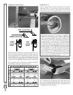
Check the Control Throws
LESS control throw
MORE
control
throw
MORE control throw
LESS
control
throw
Raise the aft end of the fuselage so the wings and stab are level (or
nearly level). Measure the control surface throws and if necessary,
use the programming in your transmitter or change the location
of the pushrods in the servo arms or in the horns on the control
surfaces to get the recommended throws. Note that the throws
are measured at the
widest
part (front-to-back) of each surface:
If your radio does not have dual rates, we recommend setting the
throws halfway between the high and low rates.
THESE ARE THE RECOMMENDED CONTROL SURFACE THROWS:
ELEV
ATOR
RUDDER
AILERONS
7/16" [11mm]
13°
UP
DOWN
3/4" [19 mm]
19°
RIGHT
LEFT
1/2" [13mm]
17°
UP
DOWN
1/4" [6 mm]
7°
UP
DOWN
1/2" [13mm]
13°
RIGHT
LEFT
3/8" [10 mm]
12°
7/16" [11mm]
13°
3/4" [19 mm]
19°
1/2" [13mm]
17°
1/4" [6 mm]
7°
1/2" [13mm]
13°
3/8" [10 mm]
12°
UP
DOWN
HIGH RATE
LOW RATE
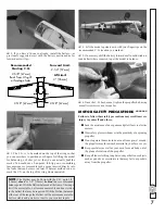
Check the C.G.
The C.G. (center of gravity) has a great effect on the way the
Hellcat
fl
ies. If the C.G. is not correct the Hellcat could be too
stable (reacting too slowly to control inputs) or too instable
(reacting too quickly to control inputs) possibly causing a crash.
The Hellcat is designed to
fl
y with either an 1800mAh or
2100mAh 3S (11.7V) battery, but it could use a little help in
the C.G.
department
and will bene
fi
t from the slightly heavier
2100mAh battery. The Hellcat should balance pretty much on
the recommended C.G. location with a 3S 2100mAh battery
positioned as far forward as it will go. It will still balance within
the recommended range with an 1800mAh battery all the way
forward, but to get it balanced
directly
on the recommended
point approximately .75 oz. [21g] may be required in the nose.
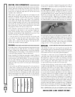
After checking the C.G., should you decide to stick an ounce
or so of ballast in the nose it is acceptable to do so directly to
the inside of the cowl. Eventually though the adhesive on the
double-sided foam tape on the back of most lead strips will
let go, so once you’ve
fi
nalized the amount of weight, attach
it more securely with a few drops of CA.
❏
1. With the battery disconnected, mount the propeller to the
motor with the included collet adapter hub—for now the propeller
hub needs to be only
fi
nger tight (in case the cowl requires removal
for adding ballast to the nose later).

