


15
16
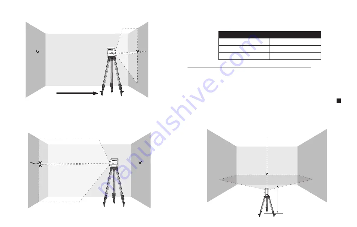
8.
Align the height of the horizontal laser line (using the tripod or by placing objects
underneath the instrument as required) with the previously marked
point b
on
wall B
.
9.
Without changing the height, rotate the instrument 180° to direct the laser beam toward
wall A.
10.
Allow the instrument to self-level and mark the center of the horizontal line on
wall A
(point a2).
B
A
b
a1
B
A
a2
b
a1
11.
Measure the vertical distance between
a1
and
a2
that indicates the actual height
deviation of the instrument.
If the actual deviation is greater than the Allowable Deviation for the corresponding
Distance Between Walls in the table below, the instrument must be serviced.
Step 2:
Checking the Leveling Accuracy of the Horizontal Line
For this check, a 16' (5m) or 30' (9m) distance to the opposite wall in a dimly lit room is
required.
1.
Place the instrument on a firm and level surface or mount the instrument onto a tripod at
the specified distance from
wall A.
2.
Turn on the instrument in the self-leveling mode by sliding the Pendulum Switch
2
to
the UNLOCK position.
3.
Direct the laser beam against
wall A (Pos.1)
and allow a few seconds for the visible line
to stabilize. Mark the center of the horizontal line projected by the instrument on
wall A
(point a1).
Distance Between Walls
Allowable Deviation
33' (10m)
± 1/8" (± 3,18mm)
66' (20m)
± 1/4" (± 6,35mm)
100' (30,5m)
± 3/8" (± 9,53mm)
A
16' (5m)
a1
Pos.1
Summary of Contents for TB-H2-LL-100-L2
Page 14: ...23 24...


