Page 6
Strakal Orsel Build Document v1
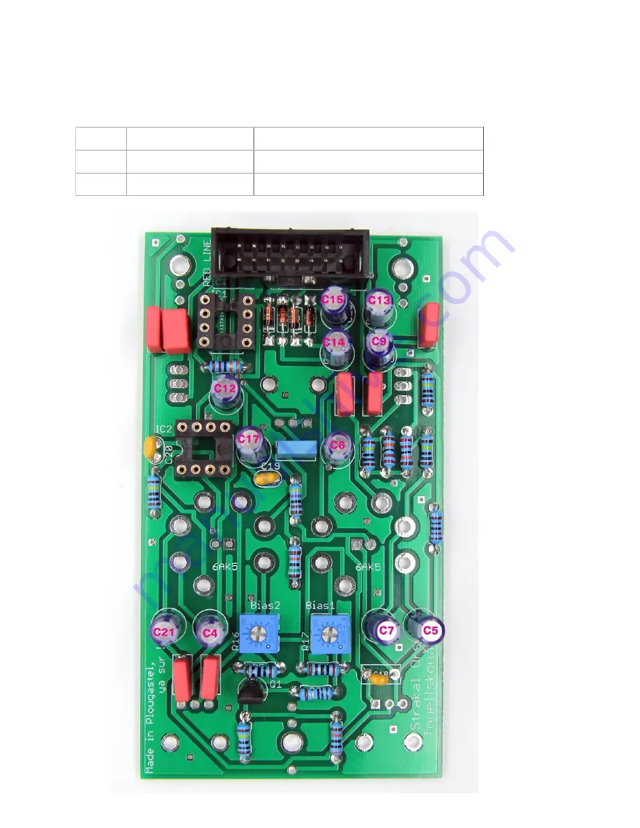
Now solder the Electrolytic caps,
the longer positive leads are marked by + signs
on the PCB
6
22uF
C9, C12, C13, C14, C15, C17
2
4.7uF
C6, C7
3
100uF
C4, C5, C21
Page 1: ...kely to end up with a destroyed damaged or defective unit if you re not hitting that standard This photo is from the Adafruit guide to excellent soldering http bit ly 1l77tF4 and is reproduced under an Attribution Sharealike creative commons license http creativecommons org licenses by sa 3 0 Start off by soldering the resistors and diodes 2 220k R1 R3 5 1M R2 R4 R8 R12 R14 1 150k R10 2 100R R5 R6...
Page 2: ...Page 2 Strakal Orsel Build Document v1 ...
Page 3: ...sel Build Document v1 Next solder the Ceramic Capacitors and Film Capacitors 6 100nF C1 C2 C3 C10 C16 C22 1 10nF C8 2 10nF C19 C20 1 1nF C11 1 51pF C18 The 10nF box capacitor supplied will either be yellow cream or blue ...
Page 4: ...rsel Build Document v1 Now solder the two trimmers two IC sockets and the power header make sure that the indent on the power header matches the pcb silkscreen facing away from the edge of the PCB 2 5k Trimmers R16 R17 ...
Page 5: ...Page 5 Strakal Orsel Build Document v1 Now solder the single transistor make sure to match the curve of the body with the silkscreen on the PCB 1 BF256 Q1 ...
Page 6: ...Page 6 Strakal Orsel Build Document v1 Now solder the Electrolytic caps the longer positive leads are marked by signs on the PCB 6 22uF C9 C12 C13 C14 C15 C17 2 4 7uF C6 C7 3 100uF C4 C5 C21 ...
Page 7: ...ut don t solder the LEDS IMPORTANT The longer lead of the LED must go to the square pad on the pcb Then place the tube holders the LED bulbs should sit around the same level as the top of the holders This can be achieved by using masking tape or something similar to hold them in place while soldering Now you can solder these components in Note The LED s supplied with kits have clear lenses but wil...
Page 8: ...of the Frontpanel hardware but DO NOT SOLDER ANYTHING YET The switches should have one nut screwed on to sit below the panel Pay attention to the pot values as shown in the picture below 1 B1M Feedback Boukl Retroaktiñ 1 A500K Gain Ampled 1 B100K Volume Gounid ...
Page 9: ...Page 9 Strakal Orsel Build Document v1 Once you have placed the the Frontpanel and screwed on nuts and washers to hold everything in place you can then solder in the pots jacks and switches ...
Page 10: ...Page 10 Strakal Orsel Build Document v1 Now paying attention to orientation fit the IC s into their sockets as shown 1 NE555 IC1 1 TL071 IC2 ...
Page 11: ... holders Important It is essential to have the module switched off when placing or replacing the tubes Do not power up this module unless the tubes are installed The two Bias trimmers are for gain stages in the circuit Touellskouarn recommend setting them in the middle to start off they can then be adjusted if desired ...