background image

QUESTIONS? 

Ask the experts at POSMicro.com.


1.800.241.6264

   Live Chat Now

   [email protected]

Monday - Friday 6 AM to 5 PM Pacific 

Time

BULk DISCOUNTS

FREE SHIPPING*

SE HaBLa 

ESpa

ñ

OL

*Free ground shipping to the continental USa on orders over $100.

For Help Call 

1.800.241.6264

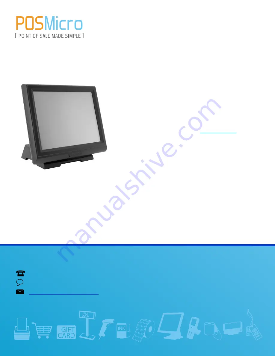
Touch Dynamic Breeze
Manual

More information available at  

POSMicro.com

Summary of Contents for Breeze Touch B13

Page 1: ...support POSMicro com Monday Friday 6 AM to 5 PM Pacific Time Bulk Discounts FREE SHIPPING SE Habla Espa ol Free ground shipping to the continental USA on orders over 100 For Help Call 1 800 241 6264...

Page 2: ...Revision v1 3 May 2011 User Manual Breeze Touch Monitor...

Page 3: ...for incidental or consequential damages in connection with the furnishing performance or use of this material This document contains proprietary information that is protected by copyright All rights...

Page 4: ...should never be placed near or over a radiator or heat register or in a built in installation unless proper ventilation is provided 7 This product should be operated from the type of power indicated...

Page 5: ...its working life Instead the device should be taken to the waste collection centers for activation of the treatment collection recycling and disposal procedure To prevent possible harm to the environm...

Page 6: ...tory Revision Number Description Revision Date 1 0 Initial release 2008 September 1 1 B13 MB upgraded MSR with finger print module added 2009 February 1 2 17 system spec added 2010 January 1 3 B16 MB...

Page 7: ...11 3 3 MSR Installation 12 3 4 2 in 1 MSR Fingerprint Module Installation 13 3 5 Power Cord Installation 14 3 6 Wall mount kit Installation for Panel display 15 4 System Disassembly 16 4 1 Removing th...

Page 8: ...carton by holding it by the foam inserts The following contents should be found in the carton 1 1 Standard Items a COM cable optional b VGA cable c Power adapter 15 17 36W d Power cord Note Power cord...

Page 9: ...7 1 2 Optional Items a MSR module b MSR Finger printer module c VFD module d Wall mount kit module...

Page 10: ...8 2 System View 2 1 Front View 2 2 Rear View MSR Stand VFD...

Page 11: ...9 2 3 I O View I O View for B13 I O View for B16 Power button OSD DC IN COM to PC VGA PS 2 PS 2 to PC USB to PC USB RJ45 COM Auto tune USB USB to PC VGA COM to PC RJ45 COM DC IN Power...

Page 12: ...screws 6 total 3 on each side c Use rubber caps on both side openings d Align larger end of the teardrop mounting holes on the VESA hinge bracket with fixing screws x4 on the rear cover of the system...

Page 13: ...11 3 2 VFD Installation a Slide the VFD module to the system VESA bracket and tighten it with the thumb screw b Connect the VFD cable to the COM port and the VFD module...

Page 14: ...n a Loosen the screws 2 on the MSR dummy cover b Fasten the grounding cable with screw 1 and connect the MSR cables to the respective connectors on the system c Connect the MSR module to the system an...

Page 15: ...Please first follow Chapter 4 3 a and go next to below steps of Chapter 4 4 a Connect 2 in 1 MSR Fingerprint cable and slide the module into the position b Tighten the screws 3 as the circles marked...

Page 16: ...14 3 5 Power Cord Installation Connect the Power cord to the power adapter The Power adapter is installed in the metal bracket fixed in the stand base...

Page 17: ...all mount kit from your distributors and follow the steps below to install the wall mount display unit Wall mount kit accessory d Remove the stand by loosening the thumb screw 1 e Place the wall mount...

Page 18: ...e the system upward to separate from the stand 4 2 Replacing the Adapter a Route the adapter cable from the hole of cable management of the stand b Disconnect the power cord from the adapter c Loosen...

Page 19: ...1 x RJ45 type to VFD Power adapter Power Source 36W 12V 3A Peripheral MSR MSR PS 2 USB 2 in 1 MSR MSR PS 2 Finger Print USB Customer Display Flush mount VFD COM Environment EMC Safety FCC Class A CE L...

Page 20: ...18 5 1 B13 Scalar board 5 1 1 B13 Scalar board layout B13 V1 1 JP3 JP9 JP2 JP7 JP4 JP8 JP11 JP10 JP12 JP5...

Page 21: ...tor CN14 Internal 12V Connector CN15 Internal USB Device Connector CN16 ELO Touch COM1 COM Port Connector Input PS1 P S2 Input Connector PS2 P S2 Output Connector PWR1 12V Input RJ45_1 COM Port Connec...

Page 22: ...n The monitor powers on as soon as it is connected to power Power Mode Off The monitor has to be switched on with the power button 2 RJ45 1 COM Power Setting Function Location JP9 1 2 3 4 COM RI COM 5...

Page 23: ...or 4 CN10 COM Power Setting 5 LCD ID Setting LVDS Panel Size Support Panel Resolution Bits Channel JP5 1 2 3 4 5 6 7 8 15 6PN115052D02 1024 x 768 24 Single 15 6PN115052D01 1024 x 768 24 Single 17 6PN1...

Page 24: ...COM Setting Function Location JP2 1 2 3 4 5 6 7 8 9 11 11 12 JP3 1 2 3 4 5 6 7 8 9 10 11 12 JP7 1 2 3 4 5 6 7 8 JP8 1 2 3 4 5 6 7 8 RS232 Touch Int Ext COM 7 MSR Port Setting Function Location JP12 1...

Page 25: ...32_1_DSR Pin 7 RS232_RTS Pin 8 RS232_1_CTS Pin 9 RS232_RI Pin 10 5V or 12V COM Port Connector RS232 Input Pin 1 RS232_DCD Pin 2 RS232_RX Pin 3 RS232_TX Pin 4 RS232_DTR Pin 5 GND Pin 6 RS232_1_DSR Pin...

Page 26: ...24 5 2 B16 Motherboard 5 2 1 B16 Motherboard layout B16 V1 0 JP1...

Page 27: ...uch Panel Connector CN14 ELO Touch CN15 OSD On Off LED CN16 COM Port Connector Output PRW1 Power Adapter RJ45 1 COM Port Connector Output COM1 COM Port Connector Input VGA1 VGA Input USB2 USB Port Dow...

Page 28: ...Interface Setting Function JP6 1 2 3 4 5 6 7 8 JP8 1 2 3 4 5 6 7 8 RS232 USB 2 Touch Setting Function JP11 1 2 3 4 5 6 EXTERNAL INTERNAL 3 COM Power Setting Function JP10 1 2 3 4 5 6 COM RI COM 5V CO...

Page 29: ...rt Panel Resolution Bits Channel JP4 1 2 3 4 5 6 7 8 15 6PN115052D02 1024 x 768 24 Single 15 6PN115052D01 1024 x 768 24 Single 17 6PN117062320 6PN117062130 1280 x 1024 24 Dual Default 5 MSR Power Sett...

Page 30: ...28 6 USB Channel Setting PORT2 Function Location JP2 1 2 3 4 5 6 7 8 USB CN4 USB to Audio PORT4 Function Location JP5 1 2 3 4 5 6 7 8 MSR USB CN2 Default JP5 JP2...

Page 31: ...ind every individual driver and utility that enables you to install the drivers in the Driver CD Please insert the Driver CD into the drive and double click on the index htm to pick up the models You...

Page 32: ...Appendix B OSD Functions for B13 Board Condition SW1 SW2 SW3 SW4 SW5 Normal Mode Signal Input Mode Power No Function No Function No Function Menu Menu Mode Power Select Confirm Left Right Exit Menu Mo...

Page 33: ...31 1 In the signal input mode pressing the SW5 key to enter Menu Mode 2 Press the SW3 or SW4 key to select video icon then press the SW2 key to enter brightness adjustment...

Page 34: ...32 3 Press the SW3 or SW4 key to adjust brightness value 4 Menu mode window will automatically close when there is no command for 10 seconds...

Page 35: ...d Condition SW1 SW2 SW1 SW2 Normal Mode Signal Input Mode Power Auto Tune Menu Mode SW1 SW2 keep press 3 seconds Menu Mode Right Select No Function PS 2 Key OSD only shifts to right when press SW1 key...

Page 36: ...34 1 In the signal input mode keep pressing the SW1 SW2 key 3 seconds at the same time 2 In Press the SW1 key to select video icon then press the SW2 key to enter brightness adjustment...

Page 37: ...35 3 Press the SW1 key to adjust brightness value Brightness value 1 2 3 4 10 1 2 4 Menu mode window will automatically close when there is no command for 10 seconds...

Reviews: