background image

3

3

PORTABLE CART WARNING

(symbol provided by RETAC)

S3125A

8. ACCESSORIES

Do not place this unit on an unstable cart, stand,
tripod, bracket, or table. The unit may fall, causing
serious injury, and serious damage to the unit.

8A. An appliance and cart combination should be moved

with care. Quick stops, excessive force, and uneven
surfaces may cause the appliance and cart combina-
tion to overturn.

9. VENTILATION

Slots and openings in the cabinet back or bottom
are provided for ventilation and to ensure reliable
operation of the unit and to protect it from overheating.
These openings must not be blocked or covered.
The openings should never be blocked by placing
the unit on a bed, sofa, rug, or other  similar surface.
This unit should never be placed near or over a
radiator or heat source. This unit should not be
placed in built-in installation such as a bookcase or
rack unless proper ventilation is provided or the
manufacturer's instructions have been adhered to.

10. POWER SOURCES

This unit should be operated only from the type of
power source indicated on the rating plate. If you are
not sure of the type of power supply to your home,
consult your appliance dealer or local power com-
pany. For units intended to operate from battery
power, or other sources, refer to the respective
pages on this Owner's Manual for their operating
instructions.

11. GROUNDING OR POLARIZATION

This unit is equipped with a polarized alternating-
current line plug (a plug having one blade wider than
the other). This plug will fit into the power outlet only
one way. This is a safety feature. If you are unable
to insert the plug fully into the outlet, try reversing
the plug. If the plug should still fail to fit, contact your
electrician to replace your obsolete outlet. Instead of
the polarized alternating-current line plug, your unit
may be equipped with a 3-wire grounding-type plug
(a plug having a third (grounding) pin). This plug will
only fit into a grounding-type power outlet. This too,
is a safety feature.

If you are unable to insert the plug into the outlet,
contact your electrician to replace your obsolete
outlet. Do not defeat the safety purpose of the
grounding-type plug.

12. POWER-CORD PROTECTION

Power-supply cords should be routed so that they
are not likely to be walked on or pinched by items
placed upon or against them, paying particular
attention to cords at plugs, convenience receptacles,
and the point where they exit from the appliance.

13. LIGHTNING

To protect your unit from a lightning storm, or when
it is left unattended and unused for long periods of
time, unplug it from the wall outlet and disconnect
the antenna or cable system. This will prevent
damage to the unit due to lightning and power line
surges.

14. POWER LINES

An outside antenna system should not be located in
the vicinity of overhead power lines or other electric
light or power circuits, or where it can fall into or
against such power lines or circuits. When installing
an outside antenna system, extreme care should be
taken to keep from touching such power lines or
circuits, as contact with them might be fatal.

15. OVERLOADING

Do not overload wall outlets and extension cords, as
this can result in a risk of fire or electric shock.

16. OBJECT AND LIQUID ENTRY

Do not push objects through any openings in this unit
as they may touch dangerous voltage points or short
out parts that could result in fire or electric shock.
Never spill or spray any type of liquid into the unit.

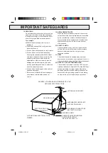
17. OUTDOOR ANTENNA GROUNDING

If an outside antenna or cable system is connected
to the unit, be sure the antenna or cable system is
grounded to provide some protection against voltage
surges and built-up static charges. Section 810 of
the National Electrical Code (NEC), ANSI/NFPA 70,
provides information with respect to proper grounding
of the mast and supporting structure, grounding of
the lead-in wire to an antenna discharge unit, size of
grounding conductors, location of antenna discharge
unit, connection to grounding electrodes, and
requirements for the grounding electrode.

IMPORTANT SAFEGUARDS

 4F22901A  COV-07

11/5/2002, 3:10

3

Summary of Contents for W525

Page 1: ...urchase a universal remote control from your local retailer please contact the remote manufacturer for the required programming code TV CATV MODE SELECTION When shipped from the factory the TV CATV menu option is set to the CATV Cable Television mode If not using CATV Cable TV set this menu option to the TV mode 4F22901A COV 07 11 5 2002 3 10 1 ...

Page 2: ...essly approved by the party responsible for compliance with the FCC Federal Communications Commission Rules could void the user s authority to operate this equipment COPYLIGHT It is permissible to record television programs films video tapes and other material only in the event that third party copyrights and other rights are not violated 5 CLEANING Unplug this unit from the wall outlet before cle...

Page 3: ...ng type power outlet This too is a safety feature If you are unable to insert the plug into the outlet contact your electrician to replace your obsolete outlet Do not defeat the safety purpose of the grounding type plug 12 POWER CORD PROTECTION Power supply cords should be routed so that they are not likely to be walked on or pinched by items placed upon or against them paying particular attention...

Page 4: ...echnician uses replacement parts specified by the manufacturer or those that have the same characteristics as the original parts Unauthorized substitutions may result in fire electric shock or other hazards 20 SAFETY CHECK Upon completion of any service or repairs to this unit ask the service technician to perform safety checks to determine that the unit is in proper operating condition 21 HEAT Th...

Page 5: ...ly 2 If the polarized AC cord does not fit into a non polarized AC outlet do not attempt to file or cut the blade It is the user s responsibility to have an electrician replace the obsolete outlet PRECAUTIONS LOCATION AND HANDLE If you cause a static discharge when touching the VCR and the VCR fails to function simply unplug the unit from the wall outlet wait 10 minutes and plug it back in The VCR...

Page 6: ...ouch Timer Recording OTR Simply by pressing the REC OTR button the VCR can be pro grammed for up to 5 hours of recording with an immedi ate start more on pg 20 Automatic Power On When loading a cassette tape this VCR will automatically turn on more on pg 17 Automatic Playback When loading a cassette tape with out the erase prevention tab this VCR will automatically turn on and play back the casset...

Page 7: ...8 2 Speed Record Records two tape speeds SP SLP more on pg 18 Stereo MTS SAP Reception This VCR is designed to receive stereo and Second Audio Program SAP broadcasts where available more on pg 22 Front Audio Video In Jacks A VCR or other video device may be hooked up for dubbing more on pg 23 CAUTIONS FEATURES 6 LOCATION OF CONTROLS 8 BASIC CONNECTIONS 10 CATV CABLE TV CONNECTIONS 12 AUDIO VIDEO C...

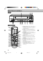
Page 8: ...ress once to stop the tape in any mode Press again to eject the tape 7 CHANNEL buttons Used to select a channel for viewing or recording 8 REC button Press once to start normal recording Additional presses activate One touch Timer Recording 9 Remote Sensor Signals from the Remote Control are received here 10 POWER indicator Lights up when the power is turned on 11 REC indicator Lights up during re...

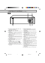
Page 9: ...enter the information in the menu mode 25 DIGITAL TRACKING button Allows automatic adjustment of tracking to minimize picture noise during playback 26 CANCEL button Used to clear the selected timer recording program 27 AUDIO SELECT button Switches sound between mono and stereo and SAP when receiving broad casts in stereo or SAP 28 INPUT SELECT button Switches the program for viewing between the VC...

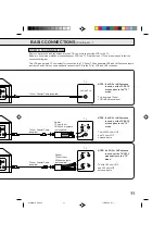
Page 10: ...a from the TV and connect it to the VCR Then connect the VCR to the TV Below are 3 common methods of connecting an antenna system to a VCR Find the type of antenna system you are using and follow the connection diagram If both VHF and UHF antennas have 300 ohm twin lead flat wires use a combiner having two 300 ohm inputs and one 75 ohm output NOTE BASIC CONNECTIONS Combination VHF UHF Antenna with...

Page 11: ...nputs TV with 300 ohm UHF and 300 ohm VHF antenna inputs VCR TO TV CONNECTION After you have connected the antenna to the VCR you must connect the VCR to the TV Below are 3 common methods of connecting your VCR to a TV Find the type of TV you are using and follow the connection diagram This VCR has a single 75 ohm output for connection to a TV If your TV has separate VHF and UHF antenna inputs num...

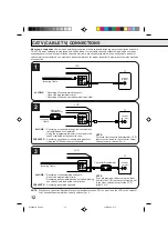
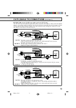
Page 12: ...ing another ALLOWS Recording of channels through the converter box scrambled and unscrambled Using the programmable timer to record only the channel selected at the converter box PREVENTS Recording one channel while watching another Using the VCR tuner to select channels 1 2 VCR Incoming Cable TV VCR Converter Descrambler Incoming Cable TV VCR Incoming Cable Converter Descrambler TV 3 ALLOWS Recor...

Page 13: ...annel Using the VCR tuner to select channels VCR Splitter Converter Descrambler TV VCR Converter Descrambler A B Switch TV Incoming Cable Splitter ALLOWS Recording of nonscrambled channels Recording of one channel while watching another Watching premium channels through the converter while recording nonscrambled channels Using the programmable timer PREVENTS Recording scrambled channels ALLOWS Rec...

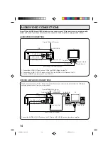
Page 14: ... OUT To VIDEO IN To ANT IN To UHF VHF OUT TV AUDIO Cable not supplied 1 Connect the VIDEO OUT jack on the VCR to the VIDEO IN jack on the TV 2 Connect the AUDIO L R OUT jacks on the VCR to the AUDIO L R IN jacks on the TV 3 Set the VIDEO TV selector of your TV to VIDEO STEREO AMPLIFIER CONNECTIONS Connect the AUDIO L R OUT jacks on the VCR to the AUX L R IN jacks on the stereo amplifier VCR To UHF...

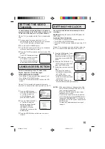
Page 15: ...en is cleared 1 Press the MENU button Press the TRACKING SET or button to select the LANGUAGE option then press the ENTER button SETTING THE CLOCK 1 2 NOTES After a power failure or disconnection of the power the timer settings will be lost In this case reset the present time Press the CANCEL button to move cursor backward for correction If you want to correct time or date while the clock is funct...

Page 16: ...4 86 94 95 99 A 5 A 1 100 125 100 125 01 5A VHF UHF CATV CHANNELS TV VHF 2 13 UHF 14 69 TO ADD DELETE CHANNELS When you don t want to receive a weak signal broadcast the Blue Back Screen can be obtained by selecting the NO NOISE BACKGROUND ON When the unit is shipped from the factory the NO NOISE BACKGROUND is set to the ON CHECK BEFORE YOU BEGIN Turn ON the TV and set to the video channel 3 or 4 ...

Page 17: ...out 4 seconds Press the STOP button once The tape will stop but remain fully loaded and ready to play will appear on the screen for about 4 seconds LOADING UNLOADING Use only video cassette tapes marked and Push the center of the tape until it is automatically retracted AUTOMATIC POWER ON The VCR will turn on automatically and the POWER indicator will light AUTOMATIC PLAY When loading a cassette t...

Page 18: ...BEGIN Turn ON the TV and set to the video channel 3 or 4 Turn ON the VCR POWER button Press the TV VCR selector button to select the VCR mode When a TV is connected with an audio video cable turn the TV on and select the video input mode on the TV will appear if you press the DISPLAY button To cancel press the DISPLAY button again 1 Press the MENU button Press the TRACKING SET or button to select ...

Page 19: ... ANOTHER After recording break off the erase prevention tab if you do not wish to record over the tape Cover the hole with adhesive tape Be careful the tape does not extend past the edges of the cassette housing Erase prevention tab Adhesive tape TO PREVENT AN ACCIDENTAL RECORDING Screwdriver NOTE Since the VCR has its own TV tuner it is not actually necessary to have the TV turned on in order to ...

Page 20: ... ON OFF AUTO REPEAT CH SET UP LANGUAGE IDIOMA LANGUE NO NOISE BACKGROUND ON OFF SAP 26 SU ENTER CANCEL MENU START END DATE CH ENTER CANCEL MENU DATE START END CH CH 125 OTR 0 30 NOTES Press the REC button to increase the time needed for recording See the chart To cancel OTR press the STOP button or turn off the power CH 125 The One touch Timer Recording feature provides a simple and convenient way...

Page 21: ... be displayed in front of the time When you load a tape the counter will change to 00 00 00 The counter does not function on nonrecorded blank sections of the tape When you rewind fast forward or play tapes through blank sections the counter stops DAY OF THE WEEK CHANNEL TAPE SPEED REAL TIME COUNTER CLOCK NOTE Do not overlap programs as portions of the conflicting programs will be lost The first r...

Page 22: ... this case the word STEREO will not appear and the sound will be in mono OUTPUT SELECTION The VHS Hi Fi audio system permits high fidelity recording of MTS STEREO TV broadcasts When viewing an MTS STEREO TV program or playing a prerecorded VHS Hi Fi STEREO videotape press the AUDIO SELECT button to allow the audio to be heard through both speakers Normally set to the Hi Fi STEREO position this but...

Page 23: ...ghted television programs films video tapes and other materials may infringe on the rights of copyright owners and violate copyright laws If you connect the VCR to another VCR or camcorder you can duplicate a previously recorded tape Make all connections before turning on the power 3 Press the REC button on the recording VCR then press the PAUSE STILL button 4 Press the PLAY button on the playback...

Page 24: ...V CATV menu option setting The erase prevention tab of the video cassette is broken off INPUT SELECT is set to the LINE mode The time is not set correctly The recording start end time is not set correctly The TIMER button has not been pressed The T REC indicator is not lit SYMPTOM CAUSE POSSIBLE SOLUTION PAGE The AC power cord is not connected Cassette is not inserted Connect the AC power cord to ...

Page 25: ...CATV 14 36 A W 37 59 AA WW 60 85 AAA ZZZ 86 94 86 94 95 99 A 5 A 1 100 125 100 125 01 5A Channel 3 or 4 Switchable In RCA 1Vp p 75 ohm Out RCA 1Vp p 75 ohm In RCA 8dB 50K ohm Out RCA 8dB 1K ohm UHF VHF IN 75 ohm coaxial UHF VHF OUT 75 ohm coaxial Hi Fi Frequency Response Hi Fi Dynamic Range F FWD REW Time at 25 C 77 F Speed Search Dimensions Weight Remote Control Storage Temperature Operapting Tem...

Page 26: ...oduct This is one way to enable TACP THI to provide you with better customer service and im proved products Failure to return the Demographic card will not affect your rights under this warranty Your Responsibility The above warranties are subject to the following conditions 1 You must retain your bill of sale or provide other proof of purchase 2 You must notify an Authorized TACP THI Service Stat...

Page 27: ...n or limitation of incidental or consequential damages so the above provisions may not apply to you ATTENTION CANADIAN CONSUMERS Canadian consumers are requested to complete the special Canadian Warranty Registration Form enclosed and forward this completed form with a copy of bill of sale to TOSHIBA OF CANADA to Register and Validate their warranty Products must be purchased from an Authorized Ca...

Page 28: ...28 4F22901A U 02 06 Printed in Thailand 4F22901A P20 LAST 11 5 2002 3 11 28 ...

Reviews: