Toshiba TV-GEN-03 Technical Training Manual Download Page 2

TOSHIBA PJTV 

Digital Convergence Alignment 


Module No. TV-GEN-03 

Page 1 of 20 


Consider this: 

Toshiba CRT based rear projection televisions allow convergence adjustments to be 
made in two areas:  

1. 

User convergence area

 - This area can be accessed through the customer 

picture menu by using the remote control or the front panel keys. 


Adjustments can only be made by remote control.   

2. 

Service Mode convergence area

 – This area should only be accessed by 

qualified service technicians.  A remote control is required for both access 
and adjustment. 


Readme:  

Qualified technicians should always align convergence in the Service 

Mode. 


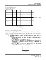
First things first - Overlays: 

Convergence overlays are service tools available for purchase through Toshiba 
National Parts or Toshiba authorized parts distributors.  The overlays are recommended 
as guides following a “worst-case” situation, such as a CRT or Digital Convergence Unit 
(DCU) replacement.  While an overlay can also be used to perform a minor alignment, 
this module will assume the worst-case scenario.   
 
Each overlay kit contains all grids relative to the screen size and aspect ratio of the unit 
to be aligned.  Many older 4:3 aspect ratio units have only one grid to adjust.  Newer 4:3 
units of the same screen size also require adjustment in High Definition (HD) 
compressed mode.  This mode can be accessed through the customer menu.  
Widescreen (16:9 aspect ratio) units built prior to 2001 have up to six different picture 
size modes that require adjustment: 

1.  Full/Standard/Natural 
2.  Wide 1 
3.  Wide 2 
4.  Wide 3 
5.  HD Full 
6. HD Standard 

Widescreen units built before the HD revolution have only picture size modes 1 through 
4.  Widescreen units built in 2001 and later are only adjustable in FULL mode.  The 
settings for all other picture size modes are calculated from the FULL mode information 
by the DCU microprocessor. 
 
The overlays come as one complete sheet and will have to be trimmed following the 
included instructions.  Each kit also contains step-by-step, centering, focusing, and 
convergence alignment instructions.  These instructions vary according to the type of 
unit.  Kits used for more than one type contain instructions for all types covered.


Readme:

  In many cases, convergence problems have been corrected by 

exactly following the supplied instructions. 


Summary of Contents for TV-GEN-03

Page 1: ...n the TV model number and picture size identify the correct convergence overlay and grid 100 of the time 4 Following a written procedure and using the correct overlay s align the convergence to factory specifications 5 While performing a convergence alignment identify visual symptoms which indicate further troubleshooting is required at least 80 of the time Product Specific Service Manuals This tr...

Page 2: ...y kit contains all grids relative to the screen size and aspect ratio of the unit to be aligned Many older 4 3 aspect ratio units have only one grid to adjust Newer 4 3 units of the same screen size also require adjustment in High Definition HD compressed mode This mode can be accessed through the customer menu Widescreen 16 9 aspect ratio units built prior to 2001 have up to six different picture...

Page 3: ... acronym PSOL meaning Protective Screen Over Lay Following the acronym are a series of alpha numeric characters identifying the screen size and intended unit type In Example 1 40 identifies the kit for use with a 40 inch screen size X1 indicates the kit contains all grids for any unit in that screen size Example 1 PSOL40X1 In some cases there are models with different aspect ratios within a screen...

Page 4: ...pe of set The methods are described as follows 1 All digital convergence equipped units built prior to 2001 and all interlaced scan units a With the unit powered ON press and release the MUTE key on the remote control b Press the MUTE key a second time and hold c While holding the MUTE key press the MENU key on the front panel A pale blue S will appear in the upper right corner of the screen as sh...

Page 5: ...and adjusted from Service Mode Use caution whenever working in this area The rubber meets the road Convergence Alignment Readme Always allow the set to warm up for at least 15 minutes before making any adjustments Convergence alignment instructions vary according to the unit type The instructions assume a worst case scenario such as replacing all three CRTs or the digital convergence board and the...

Page 6: ...r the convergence alignment service mode b Secure the appropriate overlay to the screen c Adjust the green geometry to match the overlay i Start in the center of the screen ii Work clockwise around the screen 6 Red convergence a Align to green 7 Blue convergence a Align to green 8 HD convergence a Progressive scan 4 3 units only b Component video signal to HD 1 input c 1080i picture on or HD image...

Page 7: ... 2 7mm 3 8mm 2 3mm 3 8mm 2 7mm 3 8mm 2 3mm 53 0 5mm 4 5mm 3 2mm 4 5mm 3 2mm 4 5mm 3 2mm 4 5mm 3 2mm 55 0 5mm 4 5mm 3 2mm 4 5mm 3 2mm 4 5mm 3 2mm 4 5mm 3 2mm 56 0 5mm 4 5mm 3mm 4 5mm 2 5mm 4 5mm 3mm 4 5mm 2 5mm 57 0 5mm 4 5mm 3mm 4 5mm 2 5mm 4 5mm 3mm 4 5mm 2 5mm 61 0 5mm 5mm 3 5mm 5mm 3mm 5mm 3 5mm 5mm 3mm 65 0 5mm 5mm 3 5mm 5mm 3mm 5mm 3 5mm 5mm 3mm 71 0 5mm 5mm 3 5mm 5mm 3mm 5mm 3 5mm 5mm 3mm Ta...

Page 8: ...ing message will appear on screen for ENTER TO LOAD BACKUP DATA EXIT TO EXIT 5 Press the ENTER key on the remote as shown in Figure 5 to load the backup data a The displayed net pattern will misconverge briefly then return to a normal state Figure 5 6 Following the alignment procedure in the service manual make any necessary convergence adjustments 7 Write the new data to convergence memory by pre...

Page 9: ...splayed Touch Focus pattern is severely distorted Back up data will not load Cannot enter Service Mode Data cannot be saved after alignment Table 3 Points to remember Familiarity and practice help the technician develop confidence in performing a digital convergence alignment or determining the need for further troubleshooting Having the knowledge and necessary tools available are an important fir...

Page 10: ...t the red optical and electrical focus in the same manner 11 Push the CH RTN ENT key to turn on the blue tube and the 100 key to turn off the red tube 12 Adjust the blue optical and electrical focus in the same manner Electrically defocus the blue slightly to maintain uniform brightness Section 2 MECHANICAL TILT ADJUSTMENT 1 With the set still in convergence mode and the convergence overlay on the...

Page 11: ...n the blue tube 14 Center the red and blue crossbars using the green crossbars as a guide 15 Lock the centering rings with a pliable adhesive 16 Exit the service convergence adjustment mode as described in Section 2 Section 4 ELECTRICAL CENTERING 1 Turn the power on 2 Using a signal generator display a crosshatch pattern 3 Enter the service adjustment mode 4 Check the centering of the crosshatch p...

Page 12: ...NVERGENCE 1 Remove the overlay and press the 100 key to turn on the red tube 2 Press the 3 key until the cursor turns red 3 Align the red convergence pattern to the green pattern using the same procedure used to align the green convergence pattern to the overlay Section 7 BLUE CONVERGENCE 1 Push the 100 key to turn off the red tube and CH RTN ENT to turn on the blue tube 2 Push the 3 key until the...

Page 13: ...ID register 4 Use the volume keys to adjust the WID register until the vertical lines are close to those on the overlay 5 Use the channel up down keys to select the HIT register 6 Use the volume keys to adjust the HIT register until the horizontal lines are close to those on the overlay 7 Use the channel up down keys to select the VLIN register 8 Use the volume keys to adjust the VLIN register unt...

Page 14: ...r area of the screen Readme No mirror is needed for units that provide front access 6 From the front of the set adjust the electrical focus control for best focus in the center of the screen 7 Repeat the optical focus and then tighten the wing nut 8 Repeat the electrical focus 9 Push the 100 key to turn on the red tube and the 0 key to turn off the green tube 10 Adjust the red optical and electric...

Page 15: ...the red horizontal cross hair as far as it will go toward the bottom of the screen Note that location Set the red horizontal cross hair to the center of the two extremes 6 Repeat steps 4 and 5 for the blue cross hair 7 Repeat steps 4 5 and 6 for all user convergence adjustment points 8 Exit the customer convergence screen 9 Enter the service adjustment mode 10 Enter the service convergence adjustm...

Page 16: ...gainst the screen to reduce parallax errors Readme If the microcomputer memory IC QA02 has been replaced or the crosshatch pattern is not reasonably close to the overlay pattern make the adjustments in Section 9 WID HIT VLIN ADJUSTMENTS Then proceed with step 5 5 Push the 3 key on the remote until the blinking cursor in the upper left corner of the screen is green 6 Move the blinking cursor to the...

Page 17: ...e set back on and check the white balance 2 Refer to the appropriate Service Manual and adjust the white balance as needed 3 Check the overall picture quality using a live video signal If the picture quality is acceptable put the unit back together If the picture quality is not acceptable recheck the convergence alignment Section 10 WIDTH HEIGHT VERTICAL LINEARITY ADJUSTMENTS Readme See the notes ...

Page 18: ...er area of the screen Readme No mirror is needed for units that provide front access 6 From the front of the set adjust the electrical focus control for best focus in the center of the screen 7 Repeat the optical focus and then tighten the wing nut 8 Repeat the electrical focus 9 Push the 100 key to turn on the red tube and the 0 key to turn off the green tube 10 Adjust the red optical and electri...

Page 19: ...the red horizontal cross hair as far as it will go toward the bottom of the screen Note that location Set the red horizontal cross hair to the center of the two extremes 6 Repeat steps 4 and 5 for the blue cross hair 7 Repeat steps 4 5 and 6 for all user convergence adjustment points 8 Exit the customer convergence screen 9 Enter the service adjustment mode 10 Enter the service convergence adjustm...

Page 20: ...gainst the screen to reduce parallax errors Readme If the microcomputer memory IC QA02 has been replaced or the crosshatch pattern is not reasonably close to the overlay pattern make the adjustments in Section 9 WID HIT VLIN ADJUSTMENTS Then proceed with step 5 5 Push the 3 key on the remote until the blinking cursor in the upper left corner of the screen is green 6 Move the blinking cursor to the...

Page 21: ...l If the picture quality is acceptable put the unit back together If the picture quality is not acceptable recheck the convergence alignment Section 10 WIDTH HEIGHT VERTICAL LINEARITY ADJUSTMENTS Readme See the notes in Section 5 before performing the following procedure 1 Exit the convergence adjustment mode as described in Section 2 2 Press the MENU button on the unit control panel to display th...

Reviews: