STE85371
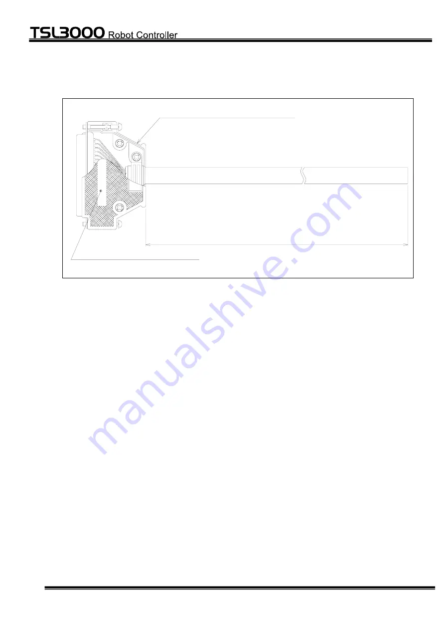
1.2 External
View
L
INP
UT
3 7 - p i n D - S U B c o n n e c t o r
c o n n e c t o r n a m e ( I N P U T )
– 9 –
Page 1: ...is delivered to the final user of Toshiba Machine s industrial robot Before operating the industrial robot read through and completely understand this manual After reading through this manual keep it nearby for future reference February 2012 TOSHIBA MACHINE CO LTD TOKYO JAPAN ...
Page 2: ...ll rights reserved No part of this document may be reproduced in any form without obtaining prior written permission from Toshiba Machine Co Ltd The information contained in this manual is subject to change without prior notice to effect improvements 2 ...
Page 3: ...trial robot controller TSL3000 These I O cables are optional For use of the cables see the Interface Manual CAUTION This manual does not include detailed descriptions on connecting the robot which are contained in the Installation Transport Manual and Interface Manual 3 ...
Page 4: ...cal damage 2 1 Injuries refer to injuries burns and electric shocks etc which do not require hospitalization or long term medical treatment 2 Physical damage refers to damages due to destruction of assets or resources Explanation of symbols Symbol Meaning of symbol This means that the action is prohibited must not be done Details of the actions actually prohibited are indicated with pictures or wo...
Page 5: ...STE85371 CAUTION To assure the safety work ranging from the robot installation to operation read through the Safety Manual before starting the work 5 ...
Page 6: ...dify parts other than those described in the instruction manual Otherwise the robot performance will deteriorate or faults will be caused Mandatory Always use the spare parts designated by Toshiba Machine when replacing the parts Service and inspect the robot on a regular basis Otherwise the robot may malfunction or cause an accident as a result CAUTION To assure the safety work ranging from the r...
Page 7: ...on Table 10 2 Output Cable for the TSL3000 Controller 12 2 1 Specifications 12 2 2 External View 13 2 3 Cable Connection Table 14 3 TR48DIOC N Input Cable 16 3 1 Specifications 16 3 2 External View 17 3 3 Cable Connection Table 18 4 TR48DIOC Output Cable 19 4 1 Specifications 19 4 2 External View 20 4 3 Cable Connection Table 21 7 ...
Page 8: ...pecifications Items Specifications Nominal sectional area of conductor 0 2 mm2 Structure of conductor 7 0 18 No of cable cores 40C Insulator material Heat proof vinyl chloride Shield material Tin plated annealed copper wire Sheath material Heat proof vinyl chloride Conductor resistance 20 C 119 Ω km or less Operating temperature 20 C 75 C See Note 1 Operating voltage AC 50 V DC 60 V Note 1 Heat pr...
Page 9: ...STE85371 1 2 External View L INPUT 37 pin D SUB connector connector name INPUT 9 ...
Page 10: ... DO_RST 27 Green White ALM_RST 9 Yellow White RUN 28 Brown White EX_SVON 10 Blue White P24G 29 Gray White P24V 11 Orange White INCOM 30 Purple White STOP 12 Pink White CYCLE 31 Light green White LOW_SPD 13 Light blue White BREAK 32 White Black SVOFF 14 Red Black 33 Green Black 15 Yellow Black 34 Brown Black P24G 16 Blue Black P24V 35 Gray Black INCOM 17 Orange Black EMS2B 36 Purple Black EMS1B 18 ...
Page 11: ...en White ALM_RST 9 Yellow White RUN 28 Brown White EX_SVON 10 Blue White P24V 29 Gray White P24G 11 Orange White INCOM 30 Purple White STOP 12 Pink White CYCLE 31 Light green White LOW_SPD 13 Light blue White BREAK 32 White Black SVOFF 14 Red Black 33 Green Black 15 Yellow Black 34 Brown Black P24V 16 Blue Black P24G 35 Gray Black INCOM 17 Orange Black EMS2B 36 Purple Black EMS1B 18 Pink Black EMS...
Page 12: ...e specifications Items Specifications Nominal sectional area of conductor 0 2 mm2 Structure of conductor 7 0 18 No of cable cores 25C Insulator material Heat proof vinyl chloride Shield material Tin plated annealed copper wire Sheath material Heat proof vinyl chloride Conductor resistance 20 C 119 Ω km or less Operating temperature 20 C 75 C See Note 4 Operating voltage AC 50 V DC 60 V Note 4 Heat...
Page 13: ...STE85371 2 2 External View L OUTPUT 25 pi n D SU B c o nn e ct o r c on n ec t or na m e O UT P UT 13 ...
Page 14: ...ange P24V 18 Purple ACK 6 Pink SV_RDY 19 Light green EXTSIG 7 Light blue SYS_RDY 20 Black White AUTORUN 8 Red White CYC_END 21 Green White LOW_ST 9 Yellow White BT_ALM 22 Brown White P24V 10 Blue White P24V 23 Gray White ALARM 11 Orange White SVST_A 24 Purple White SVST_B 12 Pink White EMSST_A 25 Light green White EMSST_B 13 Light blue White FG Case Shield Type N For details see the Interface Manu...
Page 15: ...Purple ACK 6 Pink SV_RDY 19 Light green EXTSIG 7 Light blue SYS_RDY 20 Black White AUTORUN 8 Red White CYC_END 21 Green White LOW_ST 9 Yellow White BT_ALM 22 Brown White P24G 10 Blue White P24G 23 Gray White ALARM 11 Orange White SVST_A 24 Purple White SVST_B 12 Pink White EMSST_A 25 Light green White EMSST_B 13 Light blue White FG Case Shield Type P For details see the Interface Manual 15 ...
Page 16: ...he Interface Manual STE 85364 Cable specifications Items Specifications Nominal sectional area of conductor 0 2 mm2 Structure of conductor 7 0 18 No of cable cores 40C Insulator material Heat proof vinyl chloride Shield material Tin plated annealed copper wire Sheath material Heat proof vinyl chloride Conductor resistance 20 C 119 Ω km or less Operating temperature 20 C 75 C See Note 9 Operating v...
Page 17: ...STE85371 3 2 External View L INPUT 37 pin D SUB connector connector name INPUT 17 ...
Page 18: ... 28 Brown White DI_116 DI_148 10 Blue White P24V 29 Gray White P24G 11 Orange White INCOM2 30 Purple White DI_117 DI_149 12 Pink White DI_118 DI_150 31 Light green White DI_119 DI_151 13 Light blue White DI_120 DI_152 32 White Black DI_121 DI_153 14 Red Black DI_122 DI_154 33 Green Black DI_123 DI_155 15 Yellow Black DI_124 DI_156 34 Brown Black P24V 16 Blue Black P24G 35 Gray Black INCOM3 17 Oran...
Page 19: ...he Interface Manual STE 85371 Cable specifications Items Specifications Nominal sectional area of conductor 0 2 mm2 Structure of conductor 7 0 18 No of cable cores 25C Insulator material Heat proof vinyl chloride Shield material Tin plated annealed copper wire Sheath material Heat proof vinyl chloride Conductor resistance 20 C 119 Ω km or less Operating temperature 20 C 75 C See Note 11 Operating ...
Page 20: ...STE85371 4 2 External View L OUTPUT 2 5 p i n D S UB co n ne c to r c on ne c to r n a me OU T PU T 20 ...
Page 21: ... Light blue DO_112 DO_144 20 Black White DO_113 DO_145 8 Red White DO_114 DO_146 21 Green White DO_115 DO_147 9 Yellow White DO_116 DO_148 22 Brown White P24V 10 Blue White P24V 23 Gray White DO_117 DO_149 11 Orange White DO_118 DO_150 24 Purple White DO_119 DO_151 12 Pink White DO_120 DO_152 25 Light green White DO_121 DO_153 13 Light blue White FG Case Shield Type N η As up to two 2 extension I ...
Page 22: ...O_112 DO_144 20 Black White DO_113 DO_145 8 Red White DO_114 DO_146 21 Green White DO_115 DO_147 9 Yellow White DO_116 DO_148 22 Brown White P24G 10 Blue White P24G 23 Gray White DO_117 DO_149 11 Orange White DO_118 DO_150 24 Purple White DO_119 DO_151 12 Pink White DO_120 DO_152 25 Light green White DO_121 DO_153 13 Light blue White FG Case Shield Type P η As up to two 2 extension I O units TR48D...