background image

E6581090

M-2

13

(Continued)

Error
code

Alarm

code

Problem

Possible causes

Remedies

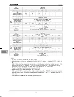
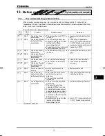
QR

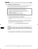
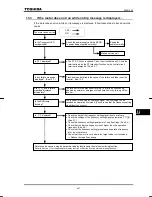
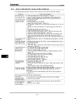
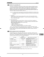
000B

Overvoltage during
deceleration

The deceleration time 

FGE

 is

too short.    (Regenerative
energy is too large.)


H

 (overvoltage limit

operation) is off.

The input voltage fluctuates
abnormally.

The power supply has a
capacity of 200kVA or more.

A power factor improvement
capacitor is opened or closed.

A system using a thyristor is
connected to the same power
distribution line.

Increase the deceleration time

FGE

.

Enable 

H

 (overvoltage

limit operation).

Insert a suitable input reactor.

QR

000C

Overvoltage during
constant-speed
operation

The input voltage fluctuates
abnormally.

The power supply has a
capacity of 200kVA or more.

A power factor improvement
capacitor is opened or closed.

A system using a thyristor is
connected to the same power
distribution line.

The motor is in a regenerative
state because the load causes
the motor to run at a frequency
higher than the inverter output
frequency.

Insert a suitable input reactor.

QN

000D

Inverter overload

The acceleration time ACC is
too short.

The DC braking amount is too
large.

The V/F setting is improper.

A restart signal is input to the
rotating motor after a
momentary stop, etc.

The load is too large.

Increase the acceleration time

CEE

.

Reduce the DC braking amount

H

 and the DC braking

time 

H

.

Check the V/F parameter
setting.

Use 

H

 (auto-restart) and

H

(ride-through control).

Use an inverter with a larger
rating.

QN

000E

Motor overload

The V/F setting is improper.

The motor is locked up.

Low-speed operation is
performed continuously.

An excessive load is applied to
the motor during operation.

Check the V/F parameter
setting.

Check the load (operated
machine).

Adjust 

QNO

 to the overload

that the motor can withstand
during operation in a low speed
range.

*

GRJ

0009

Output phase failure

A phase failure occurred in the
output line of the main circuit.

Check the main circuit output
line, motor, etc., for phase
failure.

Enable 

H

 (Output phase

failure detection).

(Continued overleaf)

Summary of Contents for TOSVERT VF-nC1

Page 1: ...trial Inverter For three phase inductive motors Single phase 100V class 0 1 to 0 75kW Single phase 200V class 0 2 to 2 2kW Three phase 200V class 0 1 to 2 2kW Instruction Manual Safety precautions Read first Contents Connection Simple operation Basic VF nC1 operations Basic parameters Variety of operation Monitoring the operation status Taking measures to satisfy the CE UL CSA Peripheral devices T...

Page 2: ...ibed in or near the symbol in either text or picture form Indicates danger What is dangerous will be described in or near the symbol in either text or picture form Indicates warning What the warning should be applied to will be described in or near the symbol in either text or picture form Limits in purpose This inverter is used for controlling speeds of three phase induction motors in general ind...

Page 3: ...er off If the equipment is continued in operation in such a state the result may be fire Call your local sales agency for repairs Always turn power off if the inverter is not used for long periods of time since there is a possibility of malfunction caused by leaks dust and other material If power is left on with the inverter in that state it may result in fire 2 1 3 3 Warning See item Prohibited c...

Page 4: ...st be those specified by Toshiba The use of any other option may result in an accident 1 4 4 1 4 4 1 4 4 1 4 4 1 4 4 Warning See item Prohibited When transporting or carrying do not hold by the front panel covers The covers may come off and the unit will drop out resulting in injury Do not install in any area where the unit would be subject to large amounts of vibration That could result in the un...

Page 5: ...1 2 1 1 4 4 Be Grounded Ground must be connected securely If the ground is not securely connected it could lead to electric shock or fire when a malfunction or current leak occurs 2 1 2 2 Warning See item Prohibited Do not attach equipment such as noise filters or surge absorbers that has built in capacitors to the output motor side terminals That could result in a fire 2 1 Operations Danger See i...

Page 6: ...ibited Do not replace parts This could be a cause of electric shock fire and bodily injury To replace parts call the local sales agency 14 2 Mandatory The equipment must be inspected every day If the equipment is not inspected and maintained errors and malfunctions may not be discovered and that could result in accidents Before inspection perform the following steps Turn off all input power to the...

Page 7: ...lace warning labels in a place where they can be easily seen and read Example of warning label If the retry function has been selected place warning labels in a location where they can be easily seen and read Example of warning label Warning Functions programmed for restart Warning Functions programmed for retry Do not go near motors and equipment Motors and equipment that have stopped temporarily...

Page 8: ...ting control mode E 7 5 10 Setting the electronic thermal E 9 5 11 Preset speed operation speeds in 15 steps E 11 6 Extended parameters F 1 6 1 Output signal related parameters F 1 6 2 Parameters related to terminal function selection F 3 6 3 Basic parameters 2 F 7 6 4 Analog signals for frequency setting F 8 6 5 Operation frequency F 10 6 6 DC braking F 11 6 7 Jump frequency Jumping resonant freq...

Page 9: ...K 1 11 3 Extended parameters K 3 12 Specifications L 1 12 1 Models and their standard specifications L 1 12 2 External dimensions weights L 4 13 Before making a service call Trip information and remedies M 1 13 1 Trip causes warnings and remedies M 1 13 2 Restoring the inverter from a trip M 6 13 3 If the motor does not run while no trip message is displayed M 7 13 4 How to determine the causes of...

Page 10: ...to the specifications of power supply and three phase induction motor being used If the inverter being used does not conform to those specifications not only will the three phase induction motor not rotate correctly but it may cause serious accidents through overheating and fire 1 2 Contents of the product code Here is explained the type and form written on the label Type Form V F N C 1 S 2 0 0 7 ...

Page 11: ...rter is placed in a mode in which the potentiometer can be used to enter operation commands RUN lamp Blinks while the inverter is in operation Monitor key Switches among operation setting and status monitor modes Enter key Reads and writes frequency and parameter data PRG lamp Lights when the inverter is in parameter setting mode Up down key Input main circuit terminal block Used to connect a powe...

Page 12: ...cover while this is lit This lamp is not provided for single phase 200V European models Connector for optional devices Used to connect an optional device Parameter writer Extension panel RS485 RS232C Control terminal block Used to control the inverter by inputting signals from an external control device and to output signals to the external device ...

Page 13: ...circuit board were factory set to the UP position to allow you to connect cables smoothly After you have connected cables to these terminals tighten them securely Caution label on the top surface See Note 1 Name Plate Ventilation slits Right side Main circuit port Control circuit port Bottom These terminals are already set to the UP position The terminals PO PA and PC are not set to the UP positio...

Page 14: ...crew driver Do not pull the power wire during unscrewing the power terminals to UP position Do not unscrew the power terminal to UP position with over torque Do not make any deformation of the cover when unscrewing the power terminals 1 3 2 Main circuit and control circuit terminal blocks 1 Main circuit terminal block When using a crimp terminal cover its caulked part with a tube or use an insulat...

Page 15: ...E6581090 A 6 1 Main circuit input terminals Main circuit output terminals Main circuit input terminals Main circuit output terminals VFNC1S 1001P 1004P VFNC1S 2002P 2007P VFNC1 2015P 2022P ...

Page 16: ...E6581090 A 7 1 Main circuit input terminals Main circuit output terminals Main circuit input terminals Main circuit output terminals VFNC1S 1007P VFNC1S 2015P 2022P VFNC1S 2002PL 2007PL ...

Page 17: ...mm Sizes of connectable wires Solid wire 0 3 to 1 5 mm2 Stranded wire 0 3 to 1 25 mm2 AWG 22 to 16 Sheath strip length 5 mm Driver bit size 2 5 0 4 mm Main circuit input terminals Main circuit output terminals 2 Control circuit terminal block The same type of terminal board is provided for all models For details of each terminal see 2 3 2 VFNC1S 2015PL 2022PL ...

Page 18: ...o that it must be adjusted in line with the rated current of the general purpose motor being used in combination High speed operation at and above 60Hz Operating at frequencies greater than 60Hz will increase noise and vibration There is also a possibility that such operation will exceed the motor s mechanical strength limits and the bearing limits so that you should inquire to the motor s manufac...

Page 19: ...with us before designing the system 1 4 2 Inverters Protecting inverters from overcurrent The inverter has an overcurrent protection function However because the programmed current level is set to the inverter s maximum applicable motor if the motor is one of small capacity and it is in operation the overcurrent level and the electronic thermal protection must be readjusted If adjustment is necess...

Page 20: ...ncy and the length of the input output wires Test and adopt the following remedies against leak current 1 Leakage current from the inverter main unit As compared with other types of inverters a large amount of current leaks from your inverter when it is used in delta connection with one phase grounded Take this into consideration when selecting an earth leakage breaker Leakage current in delta con...

Page 21: ... 1 Use the electronic thermal built into the inverter The setting of the electronic thermal is done using parameter QNO VJT 2 Reduce the inverter s PWM carrier frequency However that will increase the motor s magnetic noise Use parameter H for setting the PWM carrier frequency 3 This can be improved by installing 0 1µ 0 5µF 1000V film capacitor to the input output terminals of each phase in the th...

Page 22: ...e there is direct spraying of the following solvents or other chemicals The plastic parts may be damaged to a certain degree depending on their shape and there is a possibility of the plastic covers coming off and the plastic units being dropped If the chemical or solvent is anything other than those shown below please contact us in advance Table 1 Examples of applicable chemicals and solvents Tab...

Page 23: ...et When installing the inverter in a cabinet you are recommended to detach the caution label even if the temperature in the cabinet is below 40 C Do not install in any location that is subject to large amounts of vibration If the VF nC1 Inverter is installed near any of the equipment listed below provide measures to insure against errors in operation Solenoids Attach surge suppressor on coil Brake...

Page 24: ...n as a mechanical hold and if used for that purpose injury may result Installation location Select a location with good indoor ventilation place lengthwise in the vertical direction and attach to a metal wall surface If you are installing more than one inverter the separation between inverters should be at least 5 centimeters and they should be arranged in horizontal rows If the inverters are hori...

Page 25: ...04P 30 0 17 0 6 0 75 2007P 55 0 31 1 1 1 5 2015P 96 0 55 1 9 Three Phase 200V Class 2 2 VFNC1 2022P 126 0 72 2 5 Notes 1 The heat loss for the optional external devices input reactor DC reactor radio noise reduction filters etc is not included in the calorific values in the table 2 Case of 100 Load Continuation operation Panel designing taking into consideration the effects of noise The inverter g...

Page 26: ...f each inverter and use them where the ambient temperature will not rise above 40 C When using inverters where the ambient temperature will exceed 40 C allow a space of 5 cm or more between inverters and detach the caution label on the top surface of each inverter Ensure a space of at least 20 cm on the top and bottom of the inverters Install an air deflecting plate so that the heat rising up from...

Page 27: ...urned on without the front cover attached or closing door if enclosed in a cabinet This can result in electric shock or other injury Electrical construction work must be done by a qualified expert Connection of input power by someone who does not have that expert knowledge may result in fire or electric shock Connect output terminals motor side correctly If the phase sequence is incorrect the moto...

Page 28: ...f the size that is equivalent to or larger than those given in table 10 1 and always ground the inverter 200V voltage class D type ground former type 3 ground Use as large and short a ground wire as possible and wire it as close as possible to the inverter See the table in 10 1 for wire sizes The length of the main circuit wire in 10 1 should be no longer than 30 meters If the wire is longer than ...

Page 29: ...l circuit 1 MCCB 5 4 1 phase series Power supply R L1 S L2 1 phase series do not have T L3 terminal MCCB 2 2 1 Standard connection diagram 1 This diagram shows a standard wiring of the main circuit 1 Sink common CC When using V1 S3 terminal as an analog input terminal H or 1 Only European model has a built in noise filter 2 The terminal can be switched between FM OUT and VI S3 by changing a parame...

Page 30: ...ply R L1 S L2 1 phase series do not have T L3 terminal MCCB When using V1 S3 terminal as a logic input terminal H 1 Only European model has a built in noise filter 2 The terminal can be switched between FM OUT and VI S3 by changing a parameter 3 The terminal can also be used as an input terminal by changing a parameter 4 To use VI S3 terminal as an input terminal P15 and VI S3 must be short circui...

Page 31: ...cy meter Ammeter Control circuit MCCB 1 Ry 5 4 1 phase series Power supply R L1 S L2 1 phase series do not have T L3 terminal MCCB 2 2 2 Standard connection diagram 2 2 Source common P15 When using V1 S3 terminal as an analog input terminal H or 1 Only European model has a built in noise filter 2 The terminal can be switched between FM OUT and VI S3 by changing a parameter 3 The terminal can also ...

Page 32: ...cuit 1 VI S3 2 3 MCCB Preset speed 3 4 5 1 phase series Power supply R L1 S L2 1 phase series do not have T L3 terminal When using V1 S3 terminal as a logic input terminal H 1 Only European model has a built in noise filter 2 The terminal can be switched between FM OUT and VI S3 by changing a parameter 3 The terminal can also be used as an input terminal by changing a parameter 4 European models a...

Page 33: ...Noise reduction filter Zero phase reactor Main circuit Terminal symbol Terminal function Grounding terminal for connecting inverter case 2 grounding terminals R L1 S L2 T L3 100V class 1 phase 100V to 115V 50 60Hz 200V class 1 phase 200V to 240V 50 60Hz 3 phase 200V 240V 50 60Hz 1 phase series have R L1 and S L2 terminal U T1 V T2 W T3 Connect to a 3 phase induction motor PC This is a negative pot...

Page 34: ... causes preset speed operation S2 Input Multifunction programmable contact input Shorting across S2 CC causes preset speed operation Dry contact input 15Vdc 5mA or less Sink source selectable by changing a parameter CC Common to input output Control circuit s equipotential terminal P5 Output Power output for analog input setting 5Vdc permissible load current 10mAdc VI S3 Input Multifunction progra...

Page 35: ...default setting Monitoring of status of inverter s protection function Activation of the protection function causes circuit FLA FLC to close and circuit FLB FLC to open 250Vac 2A cosφ 1 at resistance load 30Vdc 1A 250Vac 1A cosφ 0 4 Sink logic negative common source logic positive common Logic switching of input output terminals Current flowing out turns control input terminals on These are called...

Page 36: ...witching between contact input and analog input do it before connecting cables to inverter s control circuit terminals H If switching between contact input and analog input is done after cable connection the inverter and or the external device connected might be damaged Before turning on the inverter make sure all cables are connected correctly to the control terminals When using the VI S3 termina...

Page 37: ...injury If the inverter begins to emit smoke or an unusual odor or unusual sounds immediately turn power off If the equipment is continued in operation in such a state the result may be fire Call your local sales agency for repairs Always turn power off if the inverter is not used for long periods of time Turn input power on after attaching the front cover When enclosed inside a cabinet and using w...

Page 38: ...block 1 Operation panel 2 Internal potentiometer 3 Serial communications 4 Terminal block potentiometer switching 2 Steps in setting parameters Key operated LED display Operation Displays the operation frequency operation stopped When standard monitor display selection H is set to Operation frequency CWJ The first basic parameter History CWJ is displayed EOQF Press either the key or the key to sel...

Page 39: ...minal function to an idle terminal using the programmable terminal function For coast stop open the ST CC when stopping the motor in the state described at left The monitor on the inverter at this time will display QHH Motor speed ON OFF ON OFF F CC ST CC Coast stop Short F and CC terminals run forward Open F and CC terminals slow down and stop 3 1 2 How to set the frequency 1 Setting the frequenc...

Page 40: ...the frequency using external signals to the terminal board HOQF Frequency setting 1 Setting the frequency using external potentiometer Setting frequency using the potentiometer Potentiometer control Set frequency using the potentiometer 3 10kΩ 1 4W For more detailed information on adjustments see 6 4 P5 CC VI S3 MIN MAX Frequency 60Hz 0 MIN MAX The H parameter VI S3 terminal function selection is ...

Page 41: ...tting the frequency using current input 4 20mA Current signal Setting frequency using current signals 4 20mA For more detailed information on adjustments see 6 4 Frequency 60Hz 0 4mAdc 20mAdc CC VI S3 Current signal 4 20mAdc Note The current input and voltage input functions cannot be used at the same time The H parameter VI S3 terminal function selection is used to specify a function for the VI S...

Page 42: ...de Status monitor mode Setting monitor mode MON MON MON After mode is for monitoring the output frequency and setting the frequency designated value by UP DOWN key of operation panel In it is also displayed information about status alarms during running and trips Setting frequency designated values see 3 1 2 Status alarm If there is an error in the inverter the alarm signal and the frequency will ...

Page 43: ...assign a value that is higher than the programmable range Or as a result of changing other parameters the programmed value of the parameter that is now selected exceeds the upper limit NQ An attempt has been made to assign a value that is lower than the programmable range Or as a result of changing other parameters the programmed value of the parameter that is now selected exceeds the lower limit ...

Page 44: ...the setup parameter The operation frequency is displayed Standby The settings of the parameters listed below are changed by the setup parameter When you search for I4W parameters only the parameters in the shaded area will be displayed as changed parameters Values set by each setup parameter Parameters set P Mainly in Asia R Mainly in Europe P Mainly in North America H 0 Sink logic negative common...

Page 45: ...cy Press the key to change the maximum frequency to 60Hz HJ Press the ENTER key to save the changed maximum frequency HJ and frequency are displayed alternately After this Basic parameters Selects parameter to be changed Reads the programmed parameter setting Switches to the setting monitor mode Changes the parameter setting Saves the changed value of the parameter setting Displays the same progra...

Page 46: ...elect the parameter to be changed Then press the ENTER key to display the set parameter MON Steps in key entry for extended parameters Switches to the setting monitor mode displays CWJ Selects H from basic parameters Displays the first extended parameter Selects the extended parameter to be changed Reads the programmed parameter setting MON ENT ً ٕ ENT ً ٕ ً ٕ ENT Changes the parameter setting Sav...

Page 47: ...ial parameters 1 Setting a parameter using the wizard function CWH Title Function Adjustment range Default setting CWH Wizard function 0 1 Basic setting wizard 2 Preset speed operation wizard 3 Analog signal operation wizard 4 Motor 1 2 switching operation wizard 5 Torque up wizard 0 This parameter is valid only for VFNC1 S P W type If there is anything you do not understand during this operation ...

Page 48: ...sing the or key and the ENTER key GPF GPF is dialyzed on completion of the setting of the wizard parameter group Display of parameter CWH HT H Press the MON key to exit the wizard parameter group By pressing the MON key you can return to the default monitoring mode display of operation frequency Table of parameters that can be changed using the wizard function Basic setting wizard Preset speed set...

Page 49: ...or key to display the parameter you want to set or change next and change and confirm the setting GPF On completion of a search for all parameters GPF is displayed again Display of parameter CWJ HT H To abort the search operation press the MON key Press the MON key once during a search to return to setting mode Similarly by pressing the MON key you can go back to the status monitor mode and defaul...

Page 50: ... and the setting is saved W H W T Similarly press the or key to display the parameter you want to set or change next and change and confirm the setting IT W On completion of a search for all parameters IT W is displayed again Display of parameter HT H To abort the search operation press the MON key Press the MON key once during a search to return to the setting mode Similarly by pressing the MON k...

Page 51: ...terminal selection 3 S1 H Input terminal selection 4 S2 H Input terminal selection 5 VI S3 H Sink Source selection H Output terminal selection 1 OUT FM H Output terminal selection 3 FL H Base frequency 2 Hz H Base frequency voltage 2 V H DC braking current H PWM carrier frequency H Auto restart control selection H Regenerative power ride though control H Over voltage limit operation H Slip frequen...

Page 52: ...t basic parameter History CWJ is displayed V R Press the key or the key to change to V R Pressing the ENTER key displays the programmed parameters V R will always display zero on the right the previous setting on the left Press the key or the key to change the set value To return to standard factory default setting change to KPKV Pressing the ENTER key displays KPKV while returning all parameters ...

Page 53: ...l block 1 Operation panel 2 Internal potentiometer 3 Serial communications with an optional control device 4 Terminal block internal potentiometer switching 2 Settings 外部信号 A frequency setting command is entered by inputting a signal from an external control device VI S3 terminal 0 5 10Vdc or 4 20mAdc The operation frequency is set by pressing the or key on the operation panel or an expansion oper...

Page 54: ... PNL TB OFF UP and DOWN keys on operation panel HOQF 1 PNL TB ON VI input EOQF Terminal board PNL TB OFF Internal potentiometer HOQF 2 PNL TB ON VI input EOQF Terminal board PNL TB OFF Serial communications HOQF 3 PNL TB ON VI input EOQF Terminal board FCHG OFF PNL TB OFF Internal potentiometer FCHG ON PNL TB OFF VI input HOQF 4 PNL TB ON VI input EOQF Terminal board 5 2 Meter setting and adjustme...

Page 55: ... frequency CWJ The first basic parameter CWJ is displayed HO Press either the key or the key to select HO Press the ENTER key to confirm your choice A value corresponding to the setting of HOUN FM OUT terminal functions selection is displayed Press the key or the key to adjust the meter The meter reading will change at this time but be careful because there will be no change in the inverter s digi...

Page 56: ...ameters Maximum frequency HJ 60Hz Base frequency 1 XN 60Hz Base frequency 2 H 60Hz Upper limit frequency WN 60Hz VI S3 point 2 frequency H 60Hz Motor rated speed H 1710min 1 Default setting V R Setting V R to will return all parameters to the standard values that were programmed at the factory When 3 is programmed KPKV will be displayed for a short time after setting and will then be erased and di...

Page 57: ... frequency goes from maximum frequency HJ to 0Hz Output frequency Hz FGE CEE HJ Time s 0 Parameter setting Title Function Adjustment range Default setting CEE Acceleration time 1 s 0 1 3000 seconds 10 0 FGE Deceleration time 1 s 0 1 3000 seconds 10 0 If the programmed value is shorter than the optimum acceleration deceleration time determined by load conditions overcurrent stall or overvoltage sta...

Page 58: ... 100 Output frequency Hz WN HJ Frequency setting signal Signals with a frequency higher than the frequency set with WN will not be put out Upper limit frequency 0 100 Output frequency Hz HJ NN Lower limit frequency Frequency setting signal The output frequency cannot be set below the frequency set with NN Parameter setting Title Function Adjustment range Default setting WN Upper limit frequency Hz...

Page 59: ...rol Key operated LED display Operation Displays the operation frequency operation stopped When standard monitor display selection H is set to 0 operation frequency CWJ The first basic parameter History CWJ is displayed RV Switch to the control mode selection parameter RV by pressing the key Press the ENTER key to display the parameter setting Default setting 0 V F Change the setting to 3 Vector co...

Page 60: ...e inverter with a VF motor or a motor with 6 or more poles set the torque boost parameter at 80 or so of the default setting When the inverter is used with a special motor with a particular V F ratio it requires adjustments Excessively boosting torque could results in an overcurrent trip To avoid this do not increase torque by more than 1 2 times the default torque 2 Correcting the error in rotati...

Page 61: ...ad detection operations when a standard motor is used in order to prevent overheating Setting of electronic thermal protection characteristics selection QNO Setting value Overload protection Overload stall valid invalid Setting of motor electronic thermal protection level 1 VJT If the capacity of the motor is smaller than the capacity of the inverter or the rated current of the motor is smaller th...

Page 62: ...r than the rated current of the inverter adjust the electronic thermal protection level 1 VJT so that it fits the motor s rated current If the indications are in percentages then 100 equals the inverter s rated output current A VJT 1 0 Output frequency Hz Output current reduction factor A 0 Setting of motor overload protection start level 6Hz VJT 0 6 2 Inverter over load characteristics Set to pro...

Page 63: ...teps necessary Setting from speed 1 to speed 7 Title Function Adjustment range Default setting UT UT Preset speed operation frequencies 1 7 NN WN Hz 0 0 Setting from speed 8 to speed 15 Title Function Adjustment range Default setting H H Preset speed operation frequencies 8 15 NN WN Hz 0 0 Example of a frequency setting for forward 15 speed operation Examples of preset speed contact input signals ...

Page 64: ... 3 Using other speed commands with preset speed command Command mode selection EOQF 0 Terminal board 1 Operation panel Frequency setting mode selection HOQF 0 Terminal board Analog signal 1 Operation panel 2 Potentiometer 0 Terminal board Analog signal 1 Operation panel 2 Potentiometer Entered Preset speed command Valid Note Preset speed command Not entered Analog signal Valid Operation panel Comm...

Page 65: ...as an open collector output terminal set HOUN to 1 open collector output Signals can be sent to the relay output terminals FLA FLB and FLC by changing a parameter setting Parameter setting Title Function Adjustment range Default setting H Low speed signal output frequency Hz 0 6 HJ Hz 0 6 Related parameters Title Function Adjustment range Default setting HOUN FM OUT terminal functions selection 1 ...

Page 66: ... use the FM OUT terminal as an open collector output terminal set HOUN to 1 open collector output ڎ Signals can be sent to the relay output terminals FLA FLB and FLC by changing a parameter setting Parameter for specifying a frequency Title Function Adjustment range Default setting H Speed reach setting frequency Hz 0 0 HJ Hz 0 0 Related parameters Title Function Adjustment range Default setting H...

Page 67: ... 2 1 Changing the function of the VI S3 terminal H Analog input logic input function selection Parameter setting Title Function Adjustment range Default setting H Analog input logic input function selection 0 Voltage signal 1 Current signal 2 Contact input 0 To use the VI S3 terminal as a contact input terminal in sink connection be sure to insert an adequate resistor between P15 and VI S3 Recomme...

Page 68: ...verse run or preset speed operation Use a transistor that operates at 15Vdc 5mA CC Input terminal Inverter Programmable controller Interface between inverter and programmable controller When an open collector output type programmable controller is being used for operation control turning off the programmable controller with the inverter left ON causes a wrong signal to flow into the inverter as sh...

Page 69: ...gned to the S1 terminal H 4 S1 CC JOG ON F CC ON Forward jog run S1 CC JOG ON F CC ON Reverse jog run Normal operation frequency signal input F CC ON Forward run Normal operation frequency signal input R CC ON Reverse run F CC R CC S1 JOG CC Normal operation frequency setting signal input Output frequency Hz Forward Reverse Forward Forward 0 Set frequency The jog run terminals S1 CC are enabled wh...

Page 70: ...Operating coil resistance 250 800 Ω approx Setting of output terminal functions Terminal symbol Title Function Adjustment range Default setting FM OUT H Output terminal selection 1 FM OUT 4 low speed detection signal FL H Output terminal selection 3 FL 0 13 See Section 11 10 failure FL See 2 3 for details Related parameters Title Function Adjustment range Default setting HOUN FM OUT terminal funct...

Page 71: ...H Torque boost 2 0 0 30 0 Depends on the model See Section 11 H Motor thermal protection level 2 30 100 100 1 2 The value is changed according to the set up parameter condition VFNC1 S P W type 1 60 Hz for VFNC1 S P type 2 200 V for VFNC1 S P type Setting of switching terminals The function of switching from motor 1 to motor 2 is not assigned by default to any terminal So assign this function to a...

Page 72: ... an external device Parameter setting Title Function Adjustment range Default setting H Analog input logic input function selection 0 Voltage signal input 0 10 5 Vdc 1 Current signal input 0 4 20Adc 2 Contact input 0 H VI S3 reference point 1 setting 0 100 0 H VI S3 point 1 frequency Hz 0 0 200 0 Hz 0 0 H VI S3 reference point 2 setting 0 100 100 H VI S3 point 2 frequency Hz 0 0 200 0 Hz Note 1 Do...

Page 73: ...between 0 and 20mA H 100 20mA Current signal H 0 Hz H 20 4 H 80 Hz H 1 current input 3 Adjustment of 0 5Vdc voltage input and external potentiometer P5 VI S3 CC VI S3 terminal When an external potentiometer is connected to the inverter via the P5V terminal it is necessary to set the H 47 50 approx a voltage drop might occur depending on the resistance of the resistor connected Therefore if there i...

Page 74: ...by means of frequency setting signals H Operation starting frequency Hz H Operation starting frequency hysteresis Hz Function The start stop of operation can be controlled by simply using frequency setting signals Parameter setting Title Function Adjustment range Default setting H Operation starting frequency Hz 0 0 HJ Hz 0 0 H Operation starting frequency hysteresis Hz 0 0 HJ Hz 0 0 0 A B 100 Fre...

Page 75: ...rameter setting Title Function Adjustment range Default setting H DC braking starting frequency Hz 0 0 OFF 0 1 HJ Hz 0 0 H DC braking current 0 100 50 0 H DC braking time s 0 0 OFF 0 1 20 0 sec 1 0 Time sec DC braking starting frequency H DC braking current H DC braking time H Output frequency Hz DC braking stop Operation signal F CC ON OFF Output current A 0 0 Set frequency Note During DC braking...

Page 76: ...ency H PWM carrier frequency Function 1 This parameter is used for changing the carrier frequency in order to change the tone of the magnetic noise produced by the motor This parameter is also effective in preventing the motor from resonating with its load machine or fan cover 2 In addition this parameter is used to reduce the electromagnetic noise produced by the inverter To reduce the electromag...

Page 77: ...e rated current at 4kHz is shown on the rating plate the PWM carrier frequency is set to 12kHz by default Note In order to protect the inverter PWM carrier frequency may fall automatically depending on the circumstances even if it is under the derating in accordance with above table If using foot mounted type noise reduction filter EMFAS2011Z or EMFA2006Z with VF nC1 it is necessary to decrease 5 ...

Page 78: ...any terminal If necessary assign this function to an unassigned terminal using the multi function programmable terminal function H set to The auto restart function is activated when R ST CC is short circuited after they have been opened Notes A waiting time between 200 and 300 msec is preset to allow the residual voltage in the motor to come down to a specified level during restart For this reason...

Page 79: ...age The time for which the operation of the motor is continued depends on the machine s inertia or load conditions Before using this function therefore perform a test to determine the inertial and load conditions The use of the retry function along with this function allows the motor to be restarted automatically without being brought to a stop Regenerative power ride through control is performed ...

Page 80: ...process A virtual cooling time is provided for overload tripping QN QN so that the retry process is started after the virtual cooling time and retry time In the case of overvoltage tripping QR QR tripping may recur unless the DC voltage falls below a predetermined level In the case of overheating tripping QJ tripping may recur unless the internal temperature of the inverter falls below a predeterm...

Page 81: ...g Feedback input data Setting mode Frequency setting mode HOQF Internal potentiometer setting Panel input setting Preset speed setting or External analog input H 0 voltage input VI S3 DC 0 10V H 1 current input VI S3 DC 4 20mA Note When the PI control function is enabled H 1 the VI S3 terminal is used exclusively as a feedback signal input terminal Note Do not set Frequency setting mode HOQF param...

Page 82: ...an required results in an undesirable event such as hunting Slow response Process quantity setting Time Fast response H Integral I gain adjustment parameter This parameter is used to adjust the integral gain level during PI control Any deviations remaining after proportional control are cleared to zero residual deviation offset function Increasing the I gain increases response However increasing i...

Page 83: ...2 Optimizing control characteristics Although there is no need to change the settings of the following parameters under normal conditions control characteristics may be improved by adjusting the parameters according to the motor specifications and load characteristics H Motor rated current H Motor no load current H Motor rated speed H Speed control gain H Speed control stable coefficient Title Fun...

Page 84: ...r noise Increase the value if overvoltage tripping occurs on completion of deceleration Adjust the value in increments of 10 or so while checking the effective response 6 13 Acceleration deceleration patterns and acceleration deceleration 2 CEE Acceleration time 1 s FGE Deceleration time 1 s H Acceleration time 2 s H Deceleration time 2 s H Acceleration deceleration 1 and 2 switching frequency Tit...

Page 85: ... 0 terminal block No signal for switching to acceleration deceleration 2 is set by default If necessary assign function 5 AD2 to an unassigned terminal using the input terminal selection function 6 14 Protection functions 6 14 1 Current stall setting H Stall prevention level Function If a current exceeding the level specified with H the stall prevention function is activated to decrease the output...

Page 86: ...nverter trips Panel terminal reset Power reset 6 14 3 External input trip stop H External input trip stop mode selection H DC braking time s Function These parameters allow you to specify a method for stopping the inverter when it receives an external trip stop signal via input terminals or an emergency stop signal from the operation panel When the inverter shuts down the error message G is displa...

Page 87: ...ter allows you to select a mode of detecting an output open phase failure If an open phase failure persists for one second or more the tripping function and the FL relay will be activated and at the same time the error message GRJQ will be displayed Set H to to open the motor inverter connection by switching commercial power operation to inverter operation Detection errors may occur for special mo...

Page 88: ... far larger than the inverter capacity by more than 200kVA and more than 10 times a detection error may occur If this occurs install an AC or DC reactor If the motor capacity is very small as compared with the inverter capacity no open phase failures may be detected H Disabled No tripping FL relay not activated H Enabled An open phase check is performed during operation The inverter trips if the r...

Page 89: ...ect the control mode activated when an undervoltage is detected The error message WR will be displayed if the inverter trips because of an undervoltage H Disabled The inverter shuts down but not trip FL relay not activated The inverter shuts down if the voltage drops below 64 of the rated voltage H Enabled The inverter shuts down It trips if the voltage drops below 64 of the rated voltage FL relay...

Page 90: ...___ EOQF and HOQF settings cannot be changed during operation Default Prohibited _____ All parameters are read write protected Permitted _____ EOQF and HOQF settings also can be changed during operation Prohibited _____ Frequency can be changed from the operation panel but all other parameters are read write protected Permitted _____ The emergency stop function cannot be controlled from the operat...

Page 91: ...perated under the rated load full load 1 Displayed in percentage 2 Displayed in amperes volts E E Output current 4 0A DC voltage 200V converted into AC voltage DC voltage 100 Output current 100 Conversion from into A ampere V volt can be made in status monitor mode only For the settings in the parameter list no units can be converted from into A ampere V volt An example of setting for displaying t...

Page 92: ...ntroller and so on referred to as the computer via RS232C or RS485 conversion units so that they can be operated on a network Computer linking function Data is exchanged between an inverter and a computer Monitoring the inverter s operation status such as output frequency current and voltage Commands to the inverter such as RUN and STOP commands Reading changing and writing inverter parameter sett...

Page 93: ...ng up the communications function Commands RUN STOP commands entered across a network have priority over commands from the operation panel or terminal boards Data transmission specifications Item Specifications Data transmission scheme Half duplex Connection scheme Centralized control Synchronization scheme Asynchronous Data transfer rate Default 9600 baud parameter setting Selectable from among 1...

Page 94: ... to all inverters on the network On receiving the data from the computer each inverter checks the inverter ID number contained in it Only the inverter with the specified ID number No 3 in this case decodes the command and performs the specified operation No 3 inverter sends the processing results to the host computer along with its ID number Thus only No 3 inverter operates in response to the oper...

Page 95: ...R S1 S2 VI S3 P15 P5 CC RUN STOP F R S1 S2 VI S3 P15 P5 CC RUN STOP HOQF HOQF Enter the number with the operation panel keys then press the ENTER key to confirm 3 External potentiometer setting 4 Input voltage setting 0 to 10Vdc F R S1 S2 VI S3 P15 P5 CC RUN STOP F R S1 S2 VI S3 P15 P5 CC RUN STOP Voltage signal HOQF H Input voltage signal Use the parameters H to H for this setting To use P5 set H...

Page 96: ...un use the terminals S1 to S3 Add S3 H Contact input H SS3 3 To select 15 speed run use the terminals S1 to S4 Add S4 H Contact input H SS3 H SS4 Note When using VI S3 as an input terminal be sure to short circuit P15 and VI S3 with a resistor 7 Setting by means of a remote input device 8 Setting for switching between voltage current and internal potentiometer F R S1 S2 VI S3 P15 P5 CC RUN STOP Op...

Page 97: ...OP F R S1 VI S3 P15 P5 CC RUN STOP S2 EOQF Operation panel EOQF Terminal block 3 Operation panel terminal board switching 4 Operation from an external input device F R S1 PNL TB S2 VI S3 P15 P5 CC RUN STOP F R S1 VI S3 P15 P5 CC RUN STOP S2 Optional connector EOQF Operation panel H Panel terminal board switching Switching from panel operation to terminal board operation is done by inputting a pane...

Page 98: ...nt is displayed Default setting unit Input voltage FE04 The inverter input DC voltage is displayed Default setting unit Output voltage R FE05 The inverter output voltage is displayed Default setting unit Torque current Y FE20 The torque current is displayed in PI feedback F FE22 The PI feedback value is displayed Unit frequency Inverter load factor N FE27 The inverter load factor is displayed in O...

Page 99: ...ely at 0 5 sec intervals Cumulative operation time VQ FE14 The cumulative operation time is displayed 0 01 corresponds to 1 hours Default display mode The operation frequency is displayed during operation Note 1 Press the or key to change items displayed in the status monitor mode Note 2 With the current unit selection parameter or voltage unit selection parameter you can choose between percentage...

Page 100: ...ad trip QJ 0010 Overheat trip G 0011 Emergency stop GGR 0012 E2PROM fault 1 GGR 0013 E2PROM fault 2 GGR 0014 E2PROM fault 3 GTT 0015 Inverter RAM fault GTT 0016 Inverter ROM fault GTT 0017 CPU fault trip GTT 0018 Communication error GTT 001A Current detector fault WR 001E Undervoltage trip GH 0022 Ground fault QE R 0025 Overcurrent flowing in element during acceleration QE R 0026 Overcurrent flowi...

Page 101: ...occurrence of a trip is displayed Default setting unit Torque current Y FE20 The torque current at the occurrence of a trip is displayed in PI feedback F FE22 The PI feedback value at the occurrence of a trip is displayed Unit frequency Inverter load factor N FE27 The inverter load factor at the occurrence of a trip is displayed in Output power J FE30 The output power of the inverter at the occurr...

Page 102: ... alternately at 0 5 sec intervals Cumulative operation time VQ FE14 Cumulative operation time 0 01 corresponds to 1 hours Default display mode QR Status monitor mode The LED blanks if trip occurs Note 1 Press the or key to change items displayed in the status monitor mode Note 2 The FL output is held OFF in case of a trip since the operation status immediately before the occurrence of the tip is r...

Page 103: ...ut Approval testing and confirmation testing on representative models under the circumstances based on installation and measurement so that our products should conform to each directive But we cannot confirm the conformance of the user s products to the EMC directive Since EMC environment changes according to the construction of the cubicle and the relation of other installed electric equipment an...

Page 104: ... bundling cross the wires where necessary 3 Install EMI filter and inverter on the same metal back plate in an inverter panel The metal back plate or the cubicle must be grounded absolutely by using short thick wires separated from the main cables 4 Shielded cables should be grounded on the metal back plate in order to reduce the radiated noise from the other cables It is an effective measure that...

Page 105: ...NC1S 1007P EMFAS2025Z VFNC1S 2002PL With a built in filter With a built in filter VFNC1S 2004PL With a built in filter With a built in filter VFNC1S 2007PL With a built in filter With a built in filter VFNC1S 2015PL With a built in filter With a built in filter Single phase 200V class Built in filter type VFNC1S 2022PL With a built in filter With a built in filter 2 The main cables such as input t...

Page 106: ...with external signals process as following figures Fig 4 IM Inverter panel Metal Separate input and output cables Do not run input cables along side output cables Do not bundle input and output cables Shielded cables Connect to the power source Connect to the control Grounding plate EMI filter Strip the coating of the cable and fix the shielded part to the metal plate using a metal fitting P5 VI S...

Page 107: ... form RC5078 or RC9129 Radio noise filter Soshin denki Co Ltd Type form NF series 9 1 4 Low voltage directive Inverter itself is an object of the CE marking The Low Voltage Directive defines the safety of the electric equipment VF NC1 series conform to the Low Voltage directive based on EN50178 Normative standard EN50178 Electronic equipment for use in power installation Pollution degree 2 5 2 15 ...

Page 108: ...phase 200V class 2 2 VFNC1S 2022P L AWG 10 5 5 mm2 0 1 VFNC1 2001P AWG 12 3 5 mm2 0 2 VFNC1 2002P AWG 12 3 5 mm2 0 4 VFNC1 2004P AWG 12 3 5 mm2 0 75 VFNC1 2007P AWG 12 3 5 mm2 1 5 VFNC1 2015P AWG 12 3 5 mm2 Three phase 200V class 2 2 VFNC1 2022P AWG 12 3 5 mm2 3 MCCB or fuse should be connected to the input side of the EMI filter 9 2 Compliance with UL Standard and CSA Standard The VF NC1 models t...

Page 109: ...P L AIC 1000A CC J 12 max 1 5 VFNC1S 2015P L AIC 5000A CC J 22 max Single phase 200V class 2 2 VFNC1S 2022P L AIC 5000A CC J 30 max 0 1 VFNC1 2001P AIC 1000A CC J 3 max 0 2 VFNC1 2002P AIC 1000A CC J 3 max 0 4 VFNC1 2004P AIC 1000A CC J 5 max 0 75 VFNC1 2007P AIC 1000A CC J 8 max 1 5 VFNC1 2015P AIC 5000A CC J 15 max Three phase 200V class 2 2 VFNC1 2022P AIC 5000A CC J 20 max 9 2 4 Motor thermal ...

Page 110: ...1S 2004P L AWG 14 2 0 mm2 AWG 16 1 25 mm2 AWG 12 3 5 mm2 0 75 VFNC1S 2007P L AWG 14 2 0 mm2 AWG 14 2 0 mm2 AWG 12 3 5 mm2 1 5 VFNC1S 2015P L AWG 10 3 5 mm2 AWG 14 2 0 mm2 AWG 12 3 5 mm2 Single phase 200V class 2 2 VFNC1S 2022P L AWG 10 5 5 mm2 AWG 14 2 0 mm2 AWG 10 5 5 mm2 0 1 VFNC1 2001P AWG 14 2 0 mm2 AWG 16 1 25 mm2 AWG 12 3 5 mm2 0 2 VFNC1 2002P AWG 14 2 0 mm2 AWG 16 1 25 mm2 AWG 12 3 5 mm2 0 ...

Page 111: ... 5 5 9 9 0 7 LR3D056 0 2 VFNC1 2002P 5 5 9 9 1 3 LR3D066 0 4 VFNC1 2004P 5 5 9 9 2 3 LR3D076 0 75 VFNC1 2007P 10 5 9 9 3 6 LR3D086 1 5 VFNC1 2015P 15 10 9 LC1D096 9 LC1D096 6 8 LR3D126 Three phase 200V class 2 2 VFNC1 2022P 20 NJ30E NJV30E 15 NJ30E NJV30E 12 LC1D126 12 LC1D126 9 3 LR3D146 Note 1 Produced by Toshiba Schneider Electric Ltd Note 2 Be sure to attach a surge killer to the exciting coil...

Page 112: ...Notes on wiring Be sure to interlock the magnetic contactor on the secondary side with the power supply to prevent commercial power from being applied to the inverter output terminals When installing a magnetic contactor MC between the inverter and the motor avoid turning the magnetic contactor on or off during operation Turning the magnetic contactor on or off during operation causes a current to...

Page 113: ...tting wizard 2 Preset speed operation wizard 3 Analog signal operation wizard 4 Motor 1 2 switching operation wizard 5 Torque up wizard 1 0 4 1 3 EOQF 0003 Command mode selection 0 Terminal block 1 Operation panel 1 5 1 HOQF 0004 Frequency setting mode selection 0 Terminal block 1 Operation panel 2 Internal potentiometer 3 Serial communication 4 Terminal block internal potentiometer switching 2 5 ...

Page 114: ...0 0 3 5 9 VJT 0600 Motor thermal protection level 1 1 1 30 100 100 5 10 QNO 0017 Electronic thermal protection characteristic 4 0 5 10 UT 0018 Preset speed operation frequencies 1 Hz 0 1 0 01 NN WN 0 0 UT 0019 Preset speed operation frequencies 2 Hz 0 1 0 01 NN WN 0 0 UT 0020 Preset speed operation frequencies 3 Hz 0 1 0 01 NN WN 0 0 UT 0021 Preset speed operation frequencies 4 Hz 0 1 0 01 NN WN 0...

Page 115: ...54 57 6 SS1 6 2 3 H 0114 Input terminal selection 4 S2 0 40 49 54 57 7 SS2 6 2 3 H 0115 Input terminal selection 5 VI S3 5 5 17 8 SS3 6 2 3 H 0127 Sink Source selection 0 Sink 100 Source 1 99 101 200 Disabled 2 6 2 5 H 0130 Output terminal selection 1 FM OUT 6 0 13 4 LOW 6 2 6 H 0132 Output terminal selection 3 FL 0 13 10 FL 6 2 6 H 0170 Base frequency 2 Hz 0 1 0 01 25 200 2 6 3 1 H 0171 Base freq...

Page 116: ...ing current 1 1 0 100 50 6 6 1 H 0252 DC braking time S 0 1 0 1 0 0 20 0 1 0 6 6 1 H 0270 Jump frequency Hz 0 1 0 01 NN WN 0 0 6 7 H 0271 Jumping width Hz 0 1 0 01 0 0 30 0 0 0 6 7 H 0287 Preset speed operation frequencies 8 Hz 0 1 0 01 NN WN 0 0 H 0288 Preset speed operation frequencies 9 Hz 0 1 0 01 NN WN 0 0 H 0289 Preset speed operation frequencies 10 Hz 0 1 0 01 NN WN 0 0 H 0290 Preset speed ...

Page 117: ...2 Enabled forced shortened deceleration 0 6 10 4 H 0360 PI control 0 Disabled 1 Enabled 0 6 11 H 0362 Proportional P gain 0 01 0 01 0 01 100 0 0 30 6 11 H 0363 Integral I gain 0 01 0 01 0 01 100 0 0 20 6 11 Torque boost parameters Title Communication No Function Unit Minimum setting unit Panel Communication Adjustment range Default setting User setting Reference H 0401 Slip frequency gain 1 1 0 15...

Page 118: ...tained 1 Retained 0 6 14 2 H 0603 External input trip stop mode selection 0 Coast stop 1 Slowdown stop 2 Emergency DC braking 0 6 14 3 H 0605 Output phase failure detection mode selection 0 Disabled 1 Selected Output open phase is checked when operation is started for the first time after power is turned on 2 Selected Output open phase is checked each time operation is started 0 6 14 4 H 0607 Moto...

Page 119: ...ction of monitor display selection 0 Operation frequency Hz free unit 1 Frequency command Hz free unit 2 Output current A 0 6 15 3 Communication parameters Title Communication No Function Unit Minimum setting unit Panel Communication Adjustment range Default setting User setting Reference H 0800 Communication baud rate 0 1200bps 1 2400bps 2 4800bps 3 9600bps 4 19200bps 3 6 16 H 0801 Parity 0 NON n...

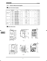
Page 120: ...P 5 8 3 4A 59 VFNC1S 2002P 8 3 1 2A 70 VFNC1S 2004P 6 2 2 0A 63 VFNC1S 2007P 5 8 3 4A 59 VFNC1S 2015P 4 6 6 2A 52 VFNC1S 2022P 4 4 8 9A 49 VFNC1 2001P 8 5 0 6A 70 VFNC1 2002P 8 3 1 2A 70 VFNC1 2004P 6 2 2 0A 63 VFNC1 2007P 5 8 3 4A 59 VFNC1 2015P 4 6 6 2A 52 VFNC1 2022P 4 4 8 9A 49 VFNC1S 2002PL 8 3 1 2A 70 VFNC1S 2004PL 6 2 2 0A 63 VFNC1S 2007PL 5 8 3 4A 59 VFNC1S 2015PL 4 6 6 2A 52 VFNC1S 2022PL...

Page 121: ...ombination of standby and reset commands ON Simultaneous input of ST and RST commands 17 ST PNL TB Combination of standby and operation panel terminal board switching ON Simultaneous input of ST and PNL TB commands 18 F JOG Combination of forward run and jog run ON Simultaneous input of F and JOG commands 19 R JOG Combination of reverse run and jog run ON Simultaneous input of R and JOG commands 2...

Page 122: ...on 2 ON Simultaneous input of R SS3 and AD2 commands 36 F SS4 AD2 Combination of forward run preset speed command 4 and acceleration deceleration 2 ON Simultaneous input of F SS4 and AD2 commands 37 R SS4 AD2 Combination of reverse run preset speed command 4 and acceleration deceleration 2 ON Simultaneous input of R SS4 and AD2 commands 38 FCHG Frequency command forced switching Enabled if HOQF 4 ...

Page 123: ...se output of LOW 6 RCH Designated frequency reach signal completion of acceleration deceleration ON Output frequency within command frequency 2 5Hz OFF Output frequency exceeding command frequency 2 5Hz 7 RCHN Inversion of designated frequency reach signal inversion of completion of acceleration deceleration Inverse output of RCH 8 RCHF Set frequency reach signal ON Output frequency within H setti...

Page 124: ...to 4 O O X O O X O X O O O X O O 10 Reset command O O O O O X O O O O O O O O 11 Trip stop command from external input device O O O 12 Operation panel terminal board switching O O O O O O O O O O O O O O 13 DC braking command O X O O O X 14 PI control prohibition O O X O O O X O X O O X O O 15 Permission of parameter editing O O O O O O O O O O O O O O 38 Frequency commands forced switching O O O ...

Page 125: ...ooling method Self cooling Forced air cooled Color Munsel 5Y8 0 5 Charge lamp LED indicating the charge status of the capacitor in the main circuit Built in filter Item Specification Input voltage 1 phase 200V Applicable motor kW 0 1 0 2 0 4 0 75 1 5 2 2 Type VFNC1S Form 2002P 2004P 2007P 2015P 2022P Capacity kVA Note 1 0 6 1 0 1 6 2 9 3 9 Rated output current A Note 2 1 4 2 4 4 0 7 5 10 0 Rated o...

Page 126: ...Rating Overload current rating 60 seconds at 150 50 reduction value Voltage frequency 1 phase 200V to 240V 50 60Hz Allowable fluctuation Voltage 10 15 Note 4 frequency 5 Power supply Ampere Interrupt Capacity A AIC 1000 1000 1000 5000 5000 Protective method IP20 Enclosed type JEM 1030 Cooling method Self cooling Forced air cooled Color Munsel 5Y8 0 5 Charge lamp None Built in filter EMC noise filt...

Page 127: ...ctable between sink source Output terminal functions selectable Selectable from among 14 functions such as frequency lower limit output signal frequency upper limit output signal low speed detection output signal and specified speed attainment output signal Open collector and relay output possible Failure detection signal 1c contact output 250Vac 1A cosφ 0 4 Operation specifications Output for fre...

Page 128: ...2004P 124 1 0 0 75 VFNC1 2007P 72 137 60 A 1 0 1 5 VFNC1 2015P 1 5 3 phase 200V 2 2 VFNC1 2022P 117 155 106 B 1 5 0 1 VFNC1S 1001P 1 0 0 2 VFNC1S 1002P 100 1 0 0 4 VFNC1S 1004P 72 124 60 A 1 0 1 phase 100V 0 75 VFNC1S 1007P 117 155 106 B 1 5 0 2 VFNC1S 2002PL 100 1 0 0 4 VFNC1S 2004PL 124 1 0 0 75 VFNC1S 2007PL 72 137 60 A 1 0 1 5 VFNC1S 2015PL 1 5 1 phase 200V Europe 2 2 VFNC1S 2022PL 117 142 155...

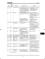
Page 129: ... during deceleration Overcurrent flowing in element during acceleration The deceleration time FGE is too short Increase the deceleration time FGE QE QE R 0003 0027 Overcurrent during operation Overcurrent flowing in element during acceleration The load fluctuates abruptly The load is in an abnormal condition Reduce the load fluctuation Check the load operated machine QEC 0005 Arm overcurrent at st...

Page 130: ...s the motor to run at a frequency higher than the inverter output frequency Insert a suitable input reactor QN 000D Inverter overload The acceleration time ACC is too short The DC braking amount is too large The V F setting is improper A restart signal is input to the rotating motor after a momentary stop etc The load is too large Increase the acceleration time CEE Reduce the DC braking amount H a...

Page 131: ...e output cable or the motor A main circuit element is defective Check the cable and the motor for ground faults Make a service call G 0011 Emergency stop During automatic operation or remote operation a stop command is entered from the operation panel or a remote input device Reset the inverter GTT 0015 Main unit RAM fault The control RAM is defective Make a service call GTT 0016 Main unit ROM fau...

Page 132: ...e it may suddenly restart GTT Frequency point setting error The frequency setting signals at points 1 and 2 are set too close to each other Set the frequency setting signals at points 1 and 2 apart from each other ENT Clear command acceptable This message is displayed when pressing the STOP key while an error code is displayed Press the STOP key again to clear the trip GQHH Emergency stop command ...

Page 133: ...source logic mode Check whether cables are connected correctly and then specify a proper logic Check whether cables are connected correctly and then reset the inverter or turn it off temporarily and turn it back on Logics will be switched G UK Source logic switching confirmation alarm The input terminal is switched to source logic mode Check whether cables are connected correctly and then specify ...

Page 134: ...n follow these steps 1 Press the STOP key and make sure that ENT is displayed 2 Pressing the STOP key again will reset the inverter if the cause of the trip has already been eliminated When any overload function QN inverter overload QN motor overload is active the inverter cannot be reset by inputting a reset signal from an external device or by operation panel operation before the virtual cooling...

Page 135: ...retry function can be disabled by normal or emergency stop operation or by turning off the inverter Is displayed Is the RUN lamp blinking Check to see that the frequency setting signal is not set at zero Check the settings of the frequency setting signal parameters HOQF See 5 1 Check the frequency setting signal points 1 and 2 settings See 6 4 Check that the start up frequency is not higher than t...

Page 136: ... into the motor The load is too heavy Reduce the load If the motor runs at a low speed check whether the torque boost amount is too large See 5 9 The motor runs at a higher or lower speed than the specified one The motor has an improper voltage rating Use a motor with a proper voltage rating The motor terminal voltage is too low Check the setting of the base frequency voltage parameter H See 6 12 ...

Page 137: ...Inspection procedure Subject of inspection Inspection item Inspection cycle Inspection method Criteria for judgment 1 Dust temperature and gas Occasionally 1 Visual check check by means of a thermometer smell check 1 Improve the environment if it is found to be unfavorable 2 Drops of water or other liquid Occasionally 2 Visual check 2 Check for any trace of water condensation 1 Indoor environment ...

Page 138: ... it for functioning once every 2 years or so by supplying it with electricity for at least 5 hours with the motor disconnected It is advisable not to supply the commercial power directly to the inverter but to gradually increase the power supply voltage with a transformer 6 If the need arises conduct an insulation test on the main circuit terminal board only using a 500V insulation tester Never co...

Page 139: ...id leak Safety valve in the depressed position Measurement of electrostatic capacitance and insulation resistance Note For the replacement of consumable parts ask your nearest Toshiba branch or office The operation time is helpful for roughly determining the time of replacement For the replacement of parts contact the service network or Toshiba branch office printed on the back cover of this instr...

Page 140: ... the inverter in a well ventilated place away from heat damp dust and metal powder 2 If the printed circuit board in your inverter has an anti static cover black cover do not leave it detached from the circuit board during storage though the cover must be detached before turning on the inverter 3 If no power is supplied to the inverter for a long time the performance of its large capacity electrol...

Page 141: ...sed by improper or incorrect use or handling or unauthorized repair or modification of the inverter Failure or damage caused by the inverter falling or an accident during transportation after the purchase Failure or damage caused by fire salty water or wind corrosive gas earthquake storm or flood lightning abnormal voltage supply or other natural disasters Failure or damage caused by the use of th...

Page 142: ...waste and known as industrial waste product collectors and transporters or industrial waste disposal persons If the collection transport and disposal of industrial waste is done by someone who is not licensed for that job it is a punishable violation of the law Law on Waste Disposal and Cleaning For safety s sake do not dispose of the disused inverter yourself but ask an industrial waste disposal ...

Page 143: ...NATIONAL CORPORATION PTY LTD 2 Morton Street Parramatta NSW2150 Australia TEL 61 0 2 9768 6600 FAX 61 0 2 9890 7542 TOSHIBA INFORMATION INDUSTRIAL AND POWER SYSTEMS TAIWAN CORP 6F No66 Sec1 Shin Sheng N RD Taipei Taiwan TEL 886 0 2 2581 3639 FAX 886 0 2 2581 3631 For further information please contact your nearest Toshiba Liaison Representative or International Operations Producer Goods The data g...

Reviews: