23
22
Preparations
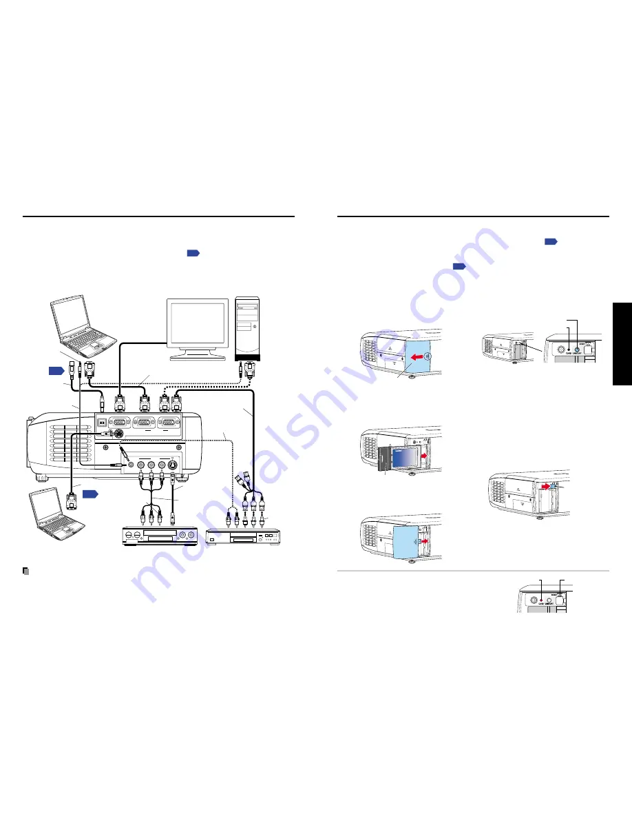
Before connection
• Read the owner’s manual of the device to be connected to the projector.
• Some types of computer cannot be used connected to this projector.
Check for an RGB output terminal, supported signal
p.69
, etc.
• Turn off the power of both devices before connection.
• The figure below is a sample connection. This does not mean that all of these devices
can or must be connected simultaneously. (Dotted lines mean items can be exchanged.)
Notes
• COMPUTER terminals 1 and 2 function identically.
• The AUDIO terminal doubles for devices connected to COMPUTER terminals 1 and 2.
Connection
How to use the PC card slot
Please read this chapter if the model you purchased includes a PC card slot.
The wireless LAN PC card enables you to connect the projector wirelessly with a
personal computer that supports IEEE802.11b based wireless LAN.
p.33
(Please note
that communication between all the computers based on IEEE802.11b and this projector
is not guaranteed.) You can also use a commercially available memory card to project
JPEG image files using this projector.
p.41
Please follow the steps below when removing
or mounting a PC card.
■
Mounting a PC card
q
Remove the PC card slot cover.
Press lightly on the circle (“O”) while
sliding the cover in the direction of the
arrow.
Card slot cover
w
Insert the PC card.
After making sure of the card
orientation, press it in firmly until it
stops.
PC Card
e
Replace the PC card slot cover.
Replace the PC card slot cover to keep
dust from entering.
■
Removing a PC card
q
Look at CARD indicator.
If it is off, proceed to step
r
.
UNMOUNT button
CARD indicator
w
Press the UNMOUNT button.
Begins processing for PC card removal
e
Wait until CARD indicator goes
out.
Never remove the PC card while lit.
Doing so could damage the PC card or
corrupt your data.
r
Press the Eject button.
The Eject button is a bit stiff, so press
firmly while supporting the projector.
Be careful to avoid injury when doing
so.
Eject button
■
If CARD indicator turns red
Press the RESET switch with a thin pin or
similar implement (it is at the bottom of a
recess).
RESET switch
CARD indicator
USB
COMPUTER
( Y/P
B
/P
R
)
S-VIDEO
VIDEO
VIDEO
R - AUDIO - L
AUDIO
MONITOR
CONTROL
1
2
p.71
p.52
Computer
Desktop computer
To audio output
To USB terminal
USB cable
Audio cable
(for computer)
(supplied)
To RGB
output
Control cable
To RS-232C terminal
Computer (for control)
RGB cable
(supplied)
To Y/C
B
/C
R
output
Green (Y)
Blue (C
B
),
Red (C
R
)
Yellow
(to video output)
To audio
output
White (L)
Red (R)
VCR
S-Video cable
(not supplied)
AV cable
(supplied)
To S-Video
output
To audio
output
White (L)
Red (R)
To audio
output
To RGB
output
Monitor cable
Mini D-sub 15P-BNC
(not supplied)
Audio cable
(not supplied)
DVD player
Conversion
adapter
BNC-pin
(not supplied)
Summary of Contents for TLP-S220
Page 37: ......


