background image

1-13

Step

Figure

Explanation

9

10

11

12

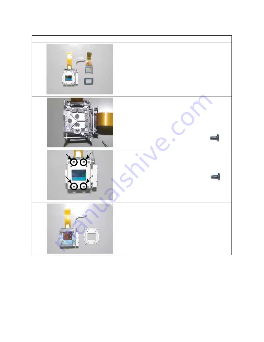
Separate the LCD panel, mask and bracket.

Note]
Keep the mask because it is used again.

The old LCD Panel and four screws are not used.

Remove 4 screws (M2 x 4).

[Note]
Keep the screws because they are used again.

Remove the bracket.

[Note]
This bracket will not use again.

Screw : type [E-4]

Remove 1 screws (M2 x 4) and remove the polarized plate
holder.

Screw : type [E-4]

3-8. LCD Panel (Continued)

Summary of Contents for TLP-780C

Page 1: ...SERVICE MANUAL FILE NO 330 200102 SUPPLEMENT 3LCD DATA PROJECTOR TLP 781U 780U TLP 781E 780E TLP 781C 780C ...

Page 2: ... ohm resistor and 0 15 uF capacitor Reverse the AC plug at the AC outlet and repeat AC voltage mea surements for each exposed metallic part Voltage mea sured must not exceed 5 25V rms This corresponds to 3 5 mA AC Any value exceeding this limit consti tutes a potential shock hazard and must be corrected immediately Many electrical and mechanical parts in this chassis have special safety related ch...

Page 3: ...k 1 21 3 14 Video Audio PC Board 1 22 3 15 Document camera 1 23 3 16 Screws For Mechanical Parts 1 24 3 17 Screws For Optical Engine 1 25 3 18 How to disconnect FFC FPC Connector 1 26 4 OPTICAL ADJUSTMENT 1 29 4 1 Preparation 1 29 4 2 Adjustment of Focus 1 31 5 ELECTRICAL ADJUSTMENT 1 33 5 1 Preparation 1 33 5 2 Shading Adjustment Software 1 34 SECTION 2 SERVICING DIAGRAMS 1 TROUBLE SHOOTING 2 1 2...

Page 4: ...s Operation of this equipment in a residential area is likely to cause harmful interference in which case the user will be required to correct the interference at his own expense WARNING Changes or modifications made to this equipment not expressly approved by Toshiba or parties authorized by Toshiba could void the user s authority to operate the equipment Notice This Class A digital apparatus com...

Page 5: ...erheating and these openings must not be blocked or covered The openings should never be blocked by placing the product on a bed sofa rug or other similar surface This product should not be placed in a built in installation such as a bookcase or rack unless proper ventilation is provided or the manufacturer fs instructions have been adhered to 5 Heat The product should be situated away from heat s...

Page 6: ... product on the other equipment Top and bottom plates of this product develops heat and may give some undesirable damage to other unit 14 Attachments Do not use attachments not recommended by the product manufacturer as they may cause hazards 9 Overloading Do not overload wall outlets extension cords or integral convenience receptacles as this can result in a risk of fire or electric shock 10 Ligh...

Page 7: ...e projector by the camera arm Doing so can result in damage or injury 21 Do not get your hands between the camera arm and the main unit when setting the camera arm back in its original position To avoid injury be careful not to get your hands caught when setting the camera arm back in its original position Families with children should be particularly careful 16 If glass components including lens ...

Page 8: ...ocuments for projection on the unit for long periods of time The heat could erase the letters on a thermal paper 24 Do not move the projector while the arm is still erect Always store the arm back in position when moving the projector Otherwise injury or damage may result 25 Do not look into the arm light while it is lit The strong light may cause damage to your eyes or sight 0 8 ...

Page 9: ... INTAKE FAN 1 P800 POWER SUPPLY TICAL ENGINE E230 PROJECTION LENS LAMP HOUSING SPEAKER BLOCK Z101 EXHAUST FAN P850 BALLAST POWER SUPPLY 2 LOCATION OF PC BOARD E101 MAIN PC BOARD E102 DRIVE PC BOARD E103 VIDEO AUDIO PC BOARD E104 SENSOR PC BOARD 1 1 E105 FAN PC BOARD E106 KEY PC BOARD Z100 INT ...

Page 10: ...ing Several kinds of screws are used and some of them need special cautions That is take care of the tapping screws securing molded parts and fine pitch screws used to secure metal parts If they are used improperly the screw holes will be easily damaged and the parts can not be fixed Step Figure Explanation 1 2 3 4 Loosen 2 screws M3 x 8 These screws are retained with split washers Remove the lamp...

Page 11: ...ve 3 screws M3 x 6 Right Side Remove 5 screws M3 x 6 Front Remove 3 screws 2 x 4 Remove front cover Note Unsnap the bottom first and then unsnap the top Screw type M 1 Screw type M 1 Front Remove 1 screw M3 x 6 Screw type M 1 Screw type M 2 Note Remove connector cover ...

Page 12: ...n 6 7 8 9 10 Rear Remove 3 screws M2 x 5 Remove rear cover Note Unsnap the bottom first and then unsnap the top Rear Remove 1 screw M3 x 6 Disconnect the key board cable yellow Screw type M 1 Screw type M 3 Top cover can be removed by lifting left edge ...

Page 13: ...Main PC Board 1 5 Step Figure Explanation 1 2 3 Remove all cables and connectors Remove 6 screws M3 x 6 Remove 1 screws M3 x 6 Note The screw here is also fixing the grand wire Screw type M 1 Screw type M 1 ...

Page 14: ... Figure Explanation 1 2 2a 2b Remove all cables and connectors Remove 4 screws M3 x 6 Note The screw here is also fixing the grand wire Screw type M 1 Note The screw here is also fixing the grand plate and grand wire 2a 2b 2a 2b ...

Page 15: ... Red from the lamp housing Remove 1 screw 3 x 8 Remove 2 screws a 3 x 8 b M3 x 6 Remove 1 hook from the bottom cabinet in the direction of this arrow Remove 1 hook from the bottom cabinet in the direction of this arrow Screw type M 4 Screw b type M 1 b a Screw a type M 4 Remove 3 screw 3 x 8 Screw type M 4 ...

Page 16: ...3 6 Ballast power Supply 1 8 Step Figure Explanation 1 2 Release 4 P C board holder by using tweezers 1 2 Disconnect the cable from the ballast power supply Plastic case is opened ...

Page 17: ...planation 1 2 2a 2b 2e 2c Remove 4 screws 3 x 12 a d Remove 1 screw 3 x6 e Enlargement a Enlargement b e Enlargement c Screw type M 3 Screw type M 4 Remove 1 screw 3 x 8 1 Screw type M 3 Remove 1 screw 3 x 6 2 Screw type M 3 d b c a e 2 1 ...

Page 18: ...3 7 Optical Engine Continued 1 10 Step Figure Explanation 2d Enlargement d ...

Page 19: ... 3 4 Remove 3 screws M3 x 8SW Note Tear off adhesive tape when you remove the screw of A Separate the main frame and sub frame from the engine block Screw type E 1 Remove 5 screws M2 x 4 Screw type E 4 A Sub frame Main frame e Bottom of main frame ...

Page 20: ...ed 1 12 Step Figure Explanation 5 6 7 8 Remove 3 screws M3 x 8SW Separate the prism block from the main frame Screw type E 1 M Prism block Remove 4 screws M2 6 x 6 Screw type E 3 Remove the sheeld plate from the prism block ...

Page 21: ... it is used again The old LCD Panel and four screws are not used Remove 4 screws M2 x 4 Note Keep the screws because they are used again Remove the bracket Note This bracket will not use again Screw type E 4 Remove 1 screws M2 x 4 and remove the polarized plate holder Screw type E 4 3 8 LCD Panel Continued ...

Page 22: ... There are 2 kinds of types of the screw 4 screws use for temporary tightening Tighten the new bracket with 4 screws M2 x 4 Note This 4 screws are from the old bracket A Side Screw type E 5 Screw type E 4 B Side Screw type E 6 B A B 3 8 LCD Panel Continued 16 Install the polarised plate and holder ...

Page 23: ...n 17 18 19 Install the LCD panel holder assembly made by step 9 to the prism block Fix the LCD panel holder assembly on the bracket with 2 screws M2x2 Fix a prism block on the lens block Note Panel holder service kit 23405058 Screw type E 7 E 7 E 5 E 6 ...

Page 24: ...Explanation 1 2 3 4 Remove 4 screws M2 5 x 8SW Remove the fitting spring from the the gap Remove the Multi PBS Note Make sure the direction of the PBS when you install Screw type E 8 Prism Lamp Lamp SIDE Prism SIDE PBS Rotation Film Multi Lens TOP VIEW Lamp ...

Page 25: ...d plate Note The film side must be faced to the LCD panel when installing and the color must be related with the color of LCD panel Color Marking Panel Side polarizer film polarizer film polarizer film 5 Whe insert the polarized plate to the sub frame fit the marking and mold edge each other plate mold Marking Engine Mold Edge ...

Page 26: ... 7 8 Remve the one screw Remove the stopper Remove the polarized plate Note The film side must be faced to the LCD panel when installing and the color must be related with the color of LCD panel Color Marking Panel Side polarizer film polarizer film polarizer film ...

Page 27: ... 3 4 5 Remove 1 screw 3 x 8 Remove intake fan block from the bottom cabinet It pulls up along with a rail Remove filter block from the intake fan block The filter is split like this Screw type M 4 Remove 3 screws 3 x 47 Screw type M 6 Fan block Rail ...

Page 28: ...Explanation 6 7 8 Remove 3 screws 3 x 8 Screw type M 4 3 11 Intake Fan Continued The intake fan block is divided into the fan senser pcb and bracket The cooling fan block is divided into the plate fan piece and bracket ...

Page 29: ...ep Figure Explanation 1 2 Remove 2 screws 3 x 8 Remove 2 screws 3 x 8 black Screw type M 4 Screw type M 8 3 13 Speaker Block Step Figure Explanation 1 2 Remove 2 screws 3 x 8 Remove 1 screws 3 x 8 Screw type M 4 Screw type M 4 ...

Page 30: ...crews 3 x 8 Remove video audio PC board from the terminal bracket Note The screw here is also fixing the grand wire Green marked Note The safety interlock switch is pushed when the lamp cover is replaced Screw type M 4 Switch Switch Switch Lamp Cover Lamp Cover Lamp Cover ...

Page 31: ...p Figure Explanation 1 2 Remove 5 screws M3 x 6 Disconnect the connector from the main body Note Please remove the screw A last Then support the camera block by hand otherwise it falls Note For disassembly of the document camera refer to page 3 6 Screw type M 1 A ...

Page 32: ...p Cover 11 Main PCB 7 Drive PCB 5 Ballast Power Supply 1 Video audio PCB 5 and Lamp House 1 Front Cover 3 Power Supply 1 Ballast Power Supply 2 Ballast cable connector 1 Intake FAN 1 Optical Engine 1 Exhaust FAN 2 and Speaker Block 4 Optical Engine 4 Exhaust FAN 2 Intake FAN A 3 M 7 Rear Cover 3 Intake FAN B 3 3 x 12 3 x 8 M 8 ...

Page 33: ...SW M2 5 x 5SW M3 x 12SW M2 5 x 14SW M2 5 x 8SW M2 x 2 LCD PANEL 3 Power Supply 1 LCD PANEL 4 This screw will not use again Bracket 4 LCD Panel connector side 2 Contained in Panel holder kit LCD Panel 2 Contained in Panel holder kit LCD Panel Bracket 2 Contained in Panel holder kit Multi PBS Cover 4 Optical Engine 1 LCD Panel 3 Optical Engine Cooling FAN 3 ...

Page 34: ...Figure Explanation 2 3 Release Two hooks Note Hooks stop on the way Please do not pull out by superfluous power FFC FPC cable can be disconnected Conformity of Location number MAIN PCB PJ701 1 Electrodes up side Electrodes up side Electrodes up side Hook ...

Page 35: ...B PJ203 PJ206 PJ207 PJ208 DRIVE PCB PJ701 PJ851 PJ901 PJ951 FANDRIVE PCB PJ2 PJ3 PJ5 1 3 18 How to disconnect FFC FPC Connector 2 Printed electrodes Release hook cover Note Hook cover stops on the way Please do not pull out by superfluous power Release Hook cover Lock Cable Connector Side view Hook cover ...

Page 36: ...tops on the way Please do not pull out by superfluous power FFC FPC cable can be disconnected Conformity of Location number VIDEO AUDIO PCB PJ401 PJ403 1 3 18 How to disconnect FFC FPC Connector 3 Release Hook Lock Cable Connector Side view Printed electrodes Hook ...

Page 37: ...er to page 1 5 1 6 4 Connect LCD panels by using flat extension cables Connect PJ851 and R Panel with extension cable Connect PJ901 and G Panel with extension cable Connect PJ951 and B Panel with extension cable 5 Connect Main PC board by using extension cable kit Be careful not to touch circuit and cabinet PJ201 Exchange 9pin long cable PJ202 Extend using 3pin cable PJ210 Extend using 4pin cable ...

Page 38: ...Adjustment When this screw A is loosened the panel moves to front and back and focus can be adjusted When these screws B are loosened the panel moves to left right up and down and convergence can be adjusted B B B B ...

Page 39: ...e Explanation 1 2 3 4 TEST PATTERN Green Cross Hatch Adjust focus by projection Lens TEST PATTERN Red Cross Hatch Move the panel in front and back and adjust the focus Tighten two screws little by little Tighten two screws when you reached to the best focus point ...

Page 40: ...TERN Red and Green Cross Hatch Move the panel in left right up and down and adjust the convergence 4 2 Adjustment of Focus ex Red panel exchange Continued 1 32 Step Figure Explanation 5 6 7 Tighten four screws ...

Page 41: ...ws P C OS windows 95 98 Adjustment software SINGO98 exe FieldAdjust exe RGB cable Serial control cable for RS 232C Connection and Setting of Personal Computer 1 Connection of personal computer Connect a computer as shown in following Fig 1 4 1 Use the supplied serial control cable for connection 2 Shading adjustment software When the shading adjustment software FieldAdjust exe is started screen li...

Page 42: ...ame and press Save button 1 When you load the data from PC select Load form File menu 3 After getting the shading data the following message appired Press OK button 1 When DRIVE PCB is exchanged Brfore Exchanging Drive PC Board Step1 Get shading data from old Drive PCB Step2 Save the data to PC memory Step3 Exchange the Drive PCB Step4 Set the old data to new Drive PCB 1 3 Set the shading data to ...

Page 43: ...exchanged Step1 Adjust the VCOM data front and celing This adjustment makes the flicker of a panel into the minimum Step2 Adjust the Shading data Step3 Set the new data to the Projector 2 1 Adjust the VCOM data 1 Select Built in Signal from Check menu This menu can output the signal pattern built in the projector 2 Set the color level and press OK button When you adjust Red VCOM set red level 100 ...

Page 44: ...utton the data moves fast 6 Nxt select Celing button and select R G or B button 8 Change the internal signal patern Set the white level 50 and press OK button 9 Select Front button and select NRSH button 10 Push 1 or 1 button change data and look for the point with which a vertical stripe serves as the minimum If you push 4 or 4 button the data moves fast 11 After adjusting push Save button 7 Afte...

Page 45: ...hange the builtin signal level corresponding to the chosen level 3 Select the internal signal patern White Patern Set the following level and press OK button Example If you select Mid1 set the builtin signal level 40 4 Select the adjusting area check box Click the up or down button to change the shading data Note When a number button is chosen a straight line can be chosen After setting push Close...

Page 46: ...llowing mesage appired Click the OK button 7 The same adjustment is made in othe colors and each four levels 1 Select Data Save form the Projector menu 2 Push Save button 8 Repeat the step of 1 to 7 until shading will be in a good state 2 3 Set the shading data to the projector ...

Page 47: ...y is NG OK Check next step NG Main PCB is NG or any cable connection is NG See 2 2 Damaged Change with new lamp Not Damaged Check Lamp cover or lamp power supply However even if the lamp has no damage there is the case it has trouble also Indicated RGB Video terminal is NG or Main PCB is NG Not Indicated Check next step Correct LCD panel is NG or PJ851 PJ901 PJ951 is NG Incorrect Main PCB is NG AT...

Page 48: ...me on Trouble with the cooling fans Error Cord 08 Intake fan 09 Lamp fan 10 Exaust fan 11 Intake fan PJ202 The power turns off System micon error Error Cord 12 Device Error 13 Status Error Solution Check the power unit Check the connector Check the main PC board Change new lamp There may also be trouble in ballast power supply The lamp cover is not properly attached Unplug the power cord and reatt...

Page 49: ... 8 PJ4 PJ 201 PJ 202 PJ 210 PJ 2 06 PJ 2 07 PJ 2 08 PJ 203 PJ 204 PJ 205 MAIN PC BOARD VIDOE AUDIO PC BOARD DRIVE PC BOARD SENCOR PC BOARD RELAY PC BOARD CAMERA PC BOARD LED PC BOARD LAMP DRIVER MAIN POWER UNIT KEY PC BOARD FAN PC BOARD PJ 703 CN 2 01 CN 2 02 I N TAKE FA N1 I N TAKE FA N2 E XH A US T FA N PJ 3 60 PJ 3 00 PJ 301 PJ 302 PJ 303 ...

Page 50: ... 0V 39 FAN1 CONTROL V 0V 40 FAN1 CONTROL V 0V 41 GND 0V 42 GND 0V 43 GND 0V 44 GND 0V 45 GND 0V 46 17V 17V 47 17V 17V 48 17V 17V 49 17V 17V 50 17V 17V PJ3 MAIN PJ207 MAIN 1 PWS5V_SDA 4 5V 2 PWS5V_SCL 4 5V 3 5VLED ENB 5 0V 4 N C 0V 5 GND 0V 6 KEY REM 5 0V 7 GND 0V 8 PWS3V_SDA 3 3 V 9 PWS3V_SCL 3 3 V 10 GND 0V 11 EXT_SEL 3 3 V 12 EXT_ENB 3 3 V 13 GND 0V 14 MAIN PWR 3 3 V 15 GND 0V 16 PWLAP PWR 3 3 V...

Page 51: ...17 CAM TX 7V data 18 CAM DET 0V 19 CAM REM 5V 20 CAM LIGHT 5V 21 MAIN PWR 5V 22 CAM KEY0 5V 23 CAM LED 5V 24 CAM KEY1 5V 25 N C 0V 26 CAM KEY2 5V 27 CAM REM 5V 28 CAM KEY3 5V 29 CAM KEY5 5V 30 CAM KEY4 5V PJ206 MAIN PJ701 DRIVE 1 GND 0V 2 TxOUT0 3 3V Pulse 3 TxOUT0 3 3V Pulse 4 GND 0V 5 TxOUT1 3 3V Pulse 6 TxOUT1 3 3V Pulse 7 GND 0V 8 TxOUT2 3 3V Pulse 9 TxOUT2 3 3V Pulse 10 GND 0V 11 TxOUT3 3 3V ...

Page 52: ...o 12V 11 RV7 GV7 BV7 2 to 12V 12 RV6 GV6 BV6 2 to 12V 13 RV5 GV5 BV5 2 to 12V 14 RV4 GV4 BV4 2 to 12V 15 RV3 GV3 BV3 2 to 12V 16 RV2 GV2 BV2 2 to 12V 17 RV1 GV1 BV1 2 to 12V 18 GND 0V 19 DIRX 0 15 5V 20 ENBX1 0 to 15 5V PULSE 21 ENBX2 0 to 15 5V PULSE 22 DX 0 to 15 5V PULSE 23 CLX1 0 to 15 5V PULSE 24 NCLX1 0 to 15 5V PULSE 25 15 5V 15 5V 26 15 5V 15 5V 27 NRG 0 to 15 5V PULSE 28 CLY 0 to 15 5V PU...

Page 53: ... identical with originals The substitute replacement parts which do not have the same safety characteristics as specified in the parts list may create shock fire or other hazards NOTICE The part number must be used when ordering parts in order to assist in processing be sure to include the model number and description Y251 23101988 Y250 23306393 U 23306447 E 23306395 C ...

Page 54: ...1 2 Packing Assembly 3 2 A403 23946297 PACKING R A400 23064683 CARTON BOX A401 CARTON BOX LABEL see 3 9 A410 23918309 PARTITION Y115 23448621 SOFT CASE A403 23946297 PACKING L A280 23890937 LENS CAP ...

Page 55: ...Y211 Y212 Y260 Y260 23306393 U 23306447 E C 23101988 23062007 23555440 23565450 23565452 23565451 23565454 23589270 23589271 23589272 23589267 23589273 23589268 23589274 23589269 23372170 23372155 U EF E EG CHT E F SP U SPA GER ITA POR ENG CHT FRA CHS SPA RGB cable USB cable Audio cable for Computer Control cable RS 232C Adapter for Macintosh computer AV cable Power cord E Power cord U Power cord ...

Page 56: ...SSIS A250 23450458 REAR PANEL A232 23541089 AIR FILTER HOLDER A220 23450455 FRONT PANEL R A240 23540988 LAMP COVER A230 23540987 AIR FILTER COVER A270 23540990 CONNECTOR COVER A210 23450454 FRONT PANEL L B160 23528184 INTAKE FAN HOLDER Z102 23125891 INTACK FAN 1 Z100 23125894 INTACK FAN 2 A231 23540988 AIR FILTER B110 23436778 FOOT ADJUST ASSY ...

Page 57: ...C Board and Power Unit Assembly 3 5 E101 23771060 P C B MAIN E102 23771061 P C B DRIVE E103 23771062 P C B VIDEO AUDIO P800 23122405 POWER UNIT 63 P C B SENSOR E106 23771065 P C B KEY E105 23771064 P C B FAN ...

Page 58: ...5 23405053 for B POLARIZER IN E234 23405052 for G POLARIZER IN 5051 R IN E210G 23301432 E220G 23301429 LCD PANEL E232 23405050 SUB FRAME E231 23405049 MAIN FRAME Note Exchange same type panel E210G L3P09X 26G01G E220G L3P09X 25G01G E236 23405054 for R POLARIZER OUT E237 23405055 for G POLARIZER OUT E238 23405056 for G POLARIZER OUT ...

Page 59: ...ach plastic cover B330 B320A B310A without below button top LED filter remote filter cushion 2 kinds B320B B320 B382A B382B B382C Inner spring Flat spring Hook OVERLAY CAMERA ARM LIGHT LOCK W BALANCE GAIN The two hooks of the camera assembly are held with the two flat springs Release the two hooks from the two flat springs by using a tweezers etc when removing the assembly P P P P P P P P W W W W ...

Page 60: ...1 8 Labels 3 8 A300 23553396 781 23553397 780 A301 23553398 780 A303 23553399 781U 23553400 780U 23553429 781E 23553430 780E 23553433 781C 23553434 780C ...

Page 61: ...EL 780U CARTON BOX LABEL 781E CARTON BOX LABEL 780E CARTON BOX LABEL 781C CARTON BOX LABEL 780C PACKING PARTITION BOTTOM CHASSIS FOOT ADJUST ASSEMBLY SCREW 3x25 INTAKE FAN HOLDER SCREW 3x47 SCREW 3x47 SCREW 3x8 DOCUMENT CAMERA ASSY CAMERA ASSEMBLY BASE ARM COVER ASSEMBLY ARM ASSEMBLY 1ST JOINT COVER 3RD JOINT COVER 2A 3RD JOINT COVER 2B CAMERA BOTTOM COVER CAMERA BASE CAMERA TOP COVER LED CRUTCH B...

Page 62: ...M SOFT CASE OWNER S MANUAL ENG FRA OWNER S MANUAL ENG GER OWNER S MANUAL CHT QUICK SHEET GER for E QUICK SHEET ITA for E QUICK SHEET POR for E QUICK SHEET ENG for U QUICK SHEET CHT QUICK SHEET FRN for U QUICK SHEET CHS QUICK SHEET SPA for U OWNER S MANUAL FRA SPA for E OWNER S MANUAL SPA for U A V CABLE REMOTE CONTROL UNIT CT 90108 for E C POWER CORD BS250V5A POWER CORD U POWER CORD CEE250V6A POWE...

Page 63: ...ent camera 1 2 inches CCD 1 447 680 pixels 1392x1040 dots Lens F 3 1 f 6 4mm LCD Projection system 3 panel transmission Panel size 1 3 inches Driving system TFT active matrix Picture elements 786 432 pixels 1024x768dits Projection Lens Lens Zooming lens F 1 7 2 1 f 33 6 42 0mm Focusing Manual operation Zooming Manual operation Accessories Owner s manual 1 Owner s manual CD ROM 1 Wireless remote co...

Page 64: ...1 1 SHIBAURA 1 CHOME MINATO KU TOKYO 105 8001 JAPAN ...

Reviews: